

Page 1
1
Page 2

2
TABLE OF CONTENT
1. INSTALLATION GUIDE
2. FUNCTION KEYS
2.1 FUNCT IONS OF FRONT PANEL
2.2 FUNCT IONS OF REMOT E CONT ROL
3. TROUBLE SHOOTING
3.1 NO POWER
3.2 NO FUNCTION OF REMOTE CONTROL
3.3 NO DISPLAY OR NOT CLEAR
4. ACCES S ORIES
5. SPECIFICATIONS
Page 3
3
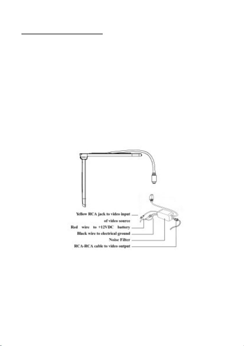
1. INSTALLATION GUIDE
1. On a towel or soft clot h, gent ly place the monitor unit "facedown" on a
stable work surface.
2. Locate t he pigtail with the DIN connector.
3. Connect t he DIN connector to t he interface cable provided.
4. Connect t he RED wire t h the positive (+) batt ery t erminal.
5. Connect t he Black wire to a chassis electrical ground point.
6. Connect t he cable with YELLOW RCA jack t o Video Input sources for
your Video P rogram mat erial.
7. In case of Video Output, connect an RCA-RCA cableon the int erface cable
box.
Page 4

4
2. FUNCTION KEYS
it will be power ON.
2.1 FRONT PANEL OF FUNCTIONS
2.2 FUNCTIONS OF REMOTE CONTROL
POWER
MENU See OSD controls
Up/Dn , ,Inc/Dec Pressorto adjust
Using On-Screen Display (OSD) Controls
You can adjust the display settings using the on-screen display (OSD) program.
Press the POWER button once
Press it again, the will be power OFF.
Page 5

5
Navigating the Menu
Press the Menu button on the front panel of the monitor to launch the OSD program.
The OSD program contains four menus:
Colour
Picture
Function
OSD Menu
Miscellaneous
Exit
Keep on pressing the Menu button t o switch between the four menus
While in a menu, press the Select button t o highlight and select an option.
When an option is selected, press the button or button to adjust the value.
When you complete your settings, the OSD menu will automatically disappear after
15 seconds, and any changes you have made will be saved. Described below are the
functions you can select and adjust in the OSD menu.
Auto Adjust If set to YES, the values of the
following items in this menu will be
automatically adjusted to the most optimal
settings. If set to NO, auto adjust will not
execute.
Auto Position If set to YES, it will adjust the
Page 6

6
display area to an adequate position and fitting
the full screen. If set to YES, auto position will
execute.
Auto Phase adjusts the ADC sampling clock phase relatively to the source video
Hsync signal. This is for minimizing video distortion or jitter. If set to YES; auto
phase will execute.
Auto Clock adjusts the number of pixels from the source video. The correct value is
equal to the horizontal total of the source video. This is for minimizing any vertical
bars or stripes visible on the screen background. If set to YES; auto clock will
execute.
Auto Colour auto adjust the RGB colours and balancing the colours to the preset
mode. If set to YES; auto colour will execute.
Picture Adjustment
H. Position moves the image rightward (with
the + button) or leftward (with the - button). The
values range from 0 to 157, and the default
setting is 29.
V. Position moves the image upward (with the +
button) or downward (with the -button). T he
values range from 0 to 23, and the default
setting is 9.
Sharpness moves the image upward (with the + button) or downward (with the
-button). The values range from 1 to 5, and the default setting is 3.
Page 7

7
Phase moves the image upward (with the + button) or downward (with the
-button). The values range from 0 to 31, and the default setting is 31.
Clock moves the image upward (with the + button) or downward (with the
-button). The values range from 1 to 200, and the default setting is 100.
Colour Adjustment
Contrast adjusts the image”s contrast. The
values range from 0 to 100, and the default
setting is 50.
Brightness adjusts the image”s brightness. T he
values range from 0 to 100, and the default
setting is 50.
Gamma Correct adjusts the image”s brightness.
The values range from 0 to 3, and the default
setting is 0.
Colour Adjust you can adjust Red, Green, Blue colour respectively to set your
preferred colour temperature. The values range from 0 to 100, and the default settings
are 50.
Miscellaneous
Signal Source basically Input source D-sub is
for PC. Additional some model video / TV
inputs for optional usage. Moves the menu
rightward (with the + button) or leftward (with
the - button).
Page 8

8
Mode Select there are two select modes. T he
default mode is 720 x 400
Reset cancels all settings you have changed and
restores the default settings of the OSD menu.
Volume Moves the menu rightward (with the + button) or leftward (with the
- button) to adjust the volume of the computer.
OS D Menu
Language allows you to choose the desired
language in the pop-up submenu. Use the +
button or - button to choose: English, German,
French, Italian, Spanish, Chinese traditional,
Chinese simple and Japanese. T he default is
English.
OSD H. Position moves the menu rightward
(with the + button) or leftward(with the -
button).
OSD V. Position moves the menu upward(with
the + button) or downward(with the - button).
OSD Timer the default setting is YES; if no button pressed, OSD menu will fall away
after 20 seconds later. If setting is No; OSD will remain on the screen.
Translucent default is Yes; means that OSD menu is translucent, can see through
slightly.
Page 9

9
3. TROUBLE SHOOTING
3.1 NO POWER
1. Make sure the power cable has been pluged in.
2. Make sure the plug has 12V~14V, may use another electrical appliance to test it.
3.2 NO FUNCTION OF REMOTE CONTROL
1. Make sure the batteries are in good condition and installed properly.
2. Make sure the remote control is aiming at the receiver, and there are no
obstacles in between.
3. Perhaps, it is too far away from the receiver. Normal distance is within 7 meters.
3.2 NO DISPLAY OR NOT CLEAR
1. Check the video signal wires if they are connected properly.
2. Check the antenna or adjust it.
3. Make sure the TV/Video being in proper position.
04. ACCESSORIES
PS2/CAR CABLE USER MANUAL
INSTALLATION BRACKET
SCREW PACK REMOT E CONT ROL
5. SPECIFICATIONS
Page 10

10
ITEM DES CRIPTION
LCD Panel: 15.0” TFT, 0.297mm, TTL
Viewing Angle -60~60 degree (H), -55~45 degree (V)
1024 x 768 (XGA)
Resolution:
800 x 600 (SVGA)
640 x 480 (VGA)
Display Colors: 16.7 M (8 bits/color)
Pixel Pitch (mm): 0.297 (H) x 0.297 (V)
Backlight Unit 2 Edge-light CCFL, Replaceable.
Contrast Ratio: 350:1
Brightness (cd/m2): 250
Display Area (mm): 304.1 (H) x 228.1 (V)
Power Supply: DC 12Vl
Power management: Power on mode:Current less than 2A
User’s Control: Power on/off, OSD control
System
1.Auto detection between NTSC/PAL.
2.SCEAM is available.
Dimension (mm): 390(L) x 365 (W) x 45 (D)
Weight 3.8 Kg
Safety certifications UL, FCC, CE, TUV,
Operation Temp.: 0~50 degree C
Environmental Condition:
StoStorage Tem p.: -20~60 degree C
Humidity: 10~90%
• Recommend for use with PYLE'S PLVWH1 wireless headphones.
 Loading...