

Page 1
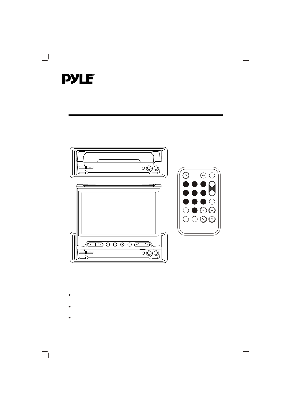
PLTV165
Mobile Video System
Vertical Adjustable And Horizontal Rotatable Panel
TFT Monitor With TV Tuner
Remote Control
www.pyleaudio.com
Page 2

CONTENTS
Important Safety Instruction .......................................................
3
Installation ....................................................................................
DIN Front-Mount (Method A) .........................................................
Installing the unit .........................................................................
Removing the unit .......................................................................
DIN Rear-Mount (Method B) ..........................................................
Electrical Connection
...................................................................
Operation ......................................................................................
Location and function of keys ........................................................
Switching on/off the unit ...............................................................
Open/close the monitor and angle adjustment ............................
Remote sensor .............................................................................
6.5 inch TFT display .....................................................................
Reset function ..............................................................................
TV Operation ...............................................................................
Selecting receiving mode .......................................................
Selecting channel ..................................................................
4
4
4
5
6
7
8
8
10
10
10
11
11
11
11
11
Menu function ........................................................................
Auto searching channels ........................................................
Volume adjustment ................................................................
Screen display .......................................................................
4:3/16:9 selector ....................................................................
Specification ...............................................................................
2
11
12
12
12
12
12
Page 3

IMPORTANT SAFETY INSTRUCTION
CAUTION:
Please read and observe all warnings and
instructions given in this owner's manual.
Keep these instructions. Retain this
booklet for future reference.
Please read the following safety
instructions carefully.
1.This set has been designed and
manufactured to assure personal
safety. Improper use can result in
electric shock or fire hazard. The
safeguards incorporated in this unit
protect you if you observe the following
procedures for installation, use and
servicing. This unit doesn't contain any
parts that can be repaired by the user.
2.The monitor is operated automatically.
Do not draw the monitor out or turn it
upward or downward manually.
Otherwise, the mechanism
construction may be harmed to some
degree.
3.When you operate the monitor with
the remote handset, do not touch the
monitor by your hands. It may harm
your fingers.
3
Page 4
INSTALLATION
Notes:
Choose the mounting location where
the unit will not interfere with the
normal driving function of the driver.
Before finally installing the unit,
connect the wiring temporarily and
make sure it is all connected up
properly and the unit and the system
work properly.
Use only the parts included with the
unit to ensure proper installation. The
use of unauthorized parts can cause
Malfunctions.
Consult with your nearest dealer if
installation requires the drilling of
holes or other modifications of the
Vehicle.
Install the unit where it does not get
in the driver's way and cannot injure
the passenger if there is a sudden
stop,like an emergency stop.
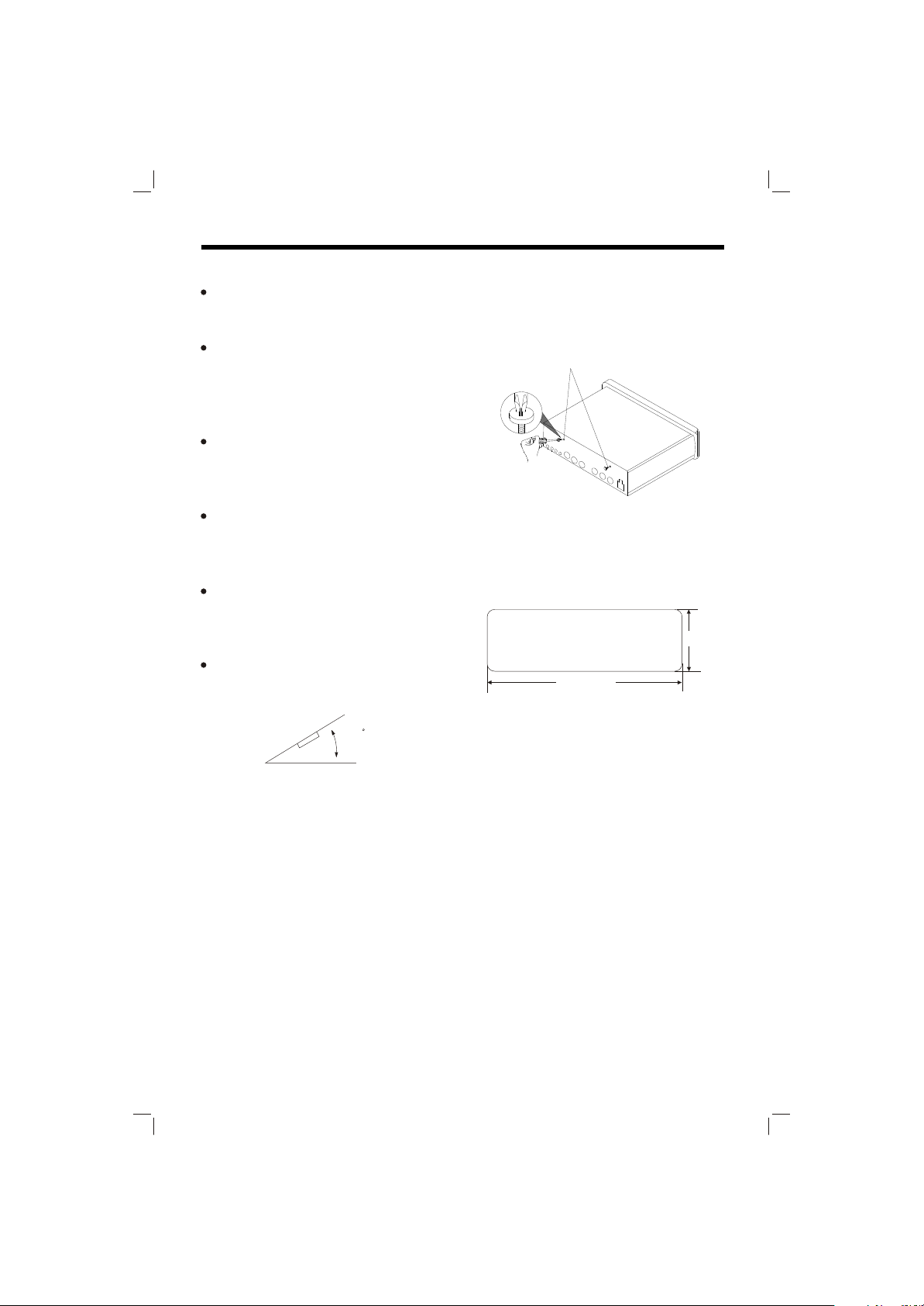
If installation angle exceeds 30 from
horizontal, the unit might not give its
optimum performance.
30
Avoid installing the unit where it would
be subject to high temperature, such
as from direct sunlight, or from hot air,
from the heater, or where it would be
subject to dust, dirt or excessive
vibration.
DIN FRONT/REAR-MOUNT
This unit be can properly installed either
from "Front"(conventional DIN
Front-mount) or "Rear"(DIN Rear-mount
installation, utilizing threaded screw holes
at the sides of the unit chassis). For
details, refer to the following illustrated
installation methods.
O
TAKE OUT SCREW BEFORE
INSTALLATION
Before install the unit, please remove
the two screws on the back of the unit.
Take out screw
before installation.
DIN FRONT-MOUNT (Method A)
Installation Opening
This unit can be installed in any
dashboard having an opening as show
below:
53mm
182mm
Installing the unit
Be sure you test all connections first, and
then follow these steps to install the unit.
1.
Make sure the ignition is turned off,
and then disconnect the cable from the
vehicle battery's negative (-) terminal.
Disconnect the wire harness and the
2.
Antenna.
Lift the top of the outer trim ring then
3.
pull it out to remove it.
The two supplied keys release tabs
4.
inside the unit's sleeve so you can
remove it. One key is for the right side
and the other is for the left side. Insert
the keys as far as they will go (with the
notches facing up) into the appropriate
slots at the middle left and right sides
of the unit. Then slide the sleeve off
the back of the unit.
4
Page 5

INSTALLATION
Sleeve
L Key
Outer Trim Ring
(Tapping Screw (5x25mm) and Plain
Washer) to attach the other end of
metal strap to a solid metal part of the
vehicle under the dashboard. This
strap also helps ensure proper electrical
grounding of the unit.
R Key
Mount the sleeve by inserting the
5.
sleeve into the opening of the
dashboard and bend open the tabs
located around the sleeve with a
screwdriver. Not all tabs will be able to
make contact, so examine which ones
will be most effective. Bending open
the appropriate tabs behind the
dashboard to secure the sleeve in
place.
Dashboard
Tabs
Screwdriver
any wires or cables.
6.
Reconnect the wire harness and the
Sleeve
antenna and be careful not to pinch
any wires or cables.
Slide the unit into the sleeve until it
7.
Locks into place.
8.
To further secure the unit, use the
supplied metal strap to secure the back
of the unit in place. Use the supplied
hardware (Hex Nut (5mm) and Spring
Washer) to attach one end of the strap
to the mounting bolt on the back of
the unit. If necessary, bend the metal
strap to fit your vehicle's mounting area.
Then use the supplied hardware
Spring Washer
Metal Strap
Mounting Bolt
Plain Washer
Tapping Screw
Reconnect the cable to the vehicle
9.
battery's negative (-) terminal. Then
replace the out trim ring.
Removing the unit
Make sure the ignition is turned off,
1.
then disconnect the cable from the
vehicle battery's negative (-) terminal.
Remove the metal strap attached the
2.
back of the unit (if attached).
Lift the top of the outer trim ring then
3.
pull it out to remove it.
Insert both of the supplied keys into the
4.
slots at the middle left and right sides of
the unit, then pull the unit out of the
dashboard.
Hex Nut
5
Page 6

INSTALLATION
DIN REAR-MOUNT (Method B)
3
5
1
2
4
1. Factory radio mounting bracket
2. Car radio mounting bracket
3. Screw
4. After aligning the car radio
mounting bracket with the factory
radio mounting bracket, tighten the
screws (5x5mm) at 2 places on
each side.
5. When fix the factory radio
mounting bracket with the screws,
use s standard-tipped screwdriver
to open the tabs of the car radio
mounting bracket to make them fit
into theholes in the factory radio
mounting bracket.
6
Page 7

ELECTRICAL CONNECTION
TV ANT
To Diversity Antenna
W
O
L
L
E
Y
N
I
2
O
E
D
I
V
AV INPUT
REMOTE
AV OUT
R
E
V
I
E
C
E
R
L
O
R
T
N
O
C
E
T
O
M
E
R
DC IN
RGB SYSTEM
)
W
E
T
I
D
H
E
R
W
N
N
I
I
L
R
2
2
O
O
I
I
D
D
U
U
A
A
E
O
T
L
I
L
E
Y
T
U
O
O
E
D
I
V
D
H
E
R
W
T
T
U
U
O
O
L
R
O
O
I
I
D
D
U
U
A
A
W
O
L
L
E
Y
A
(
3
P
)
)
U
-
K
D
K
C
E
C
A
R
L
A
(
B
B
(
C
Y
C
D
R
A
N
O
G
M
E
M
7
Page 8

OPERATION
LOCATION AND FUNCTION OF KEYS
791
3
6
5
4
8 10211
12
8
16
14
15
13
Page 9
OPERATION
LOCATION AND FUNCTION OF KEYS
18
17
20
28
29
30
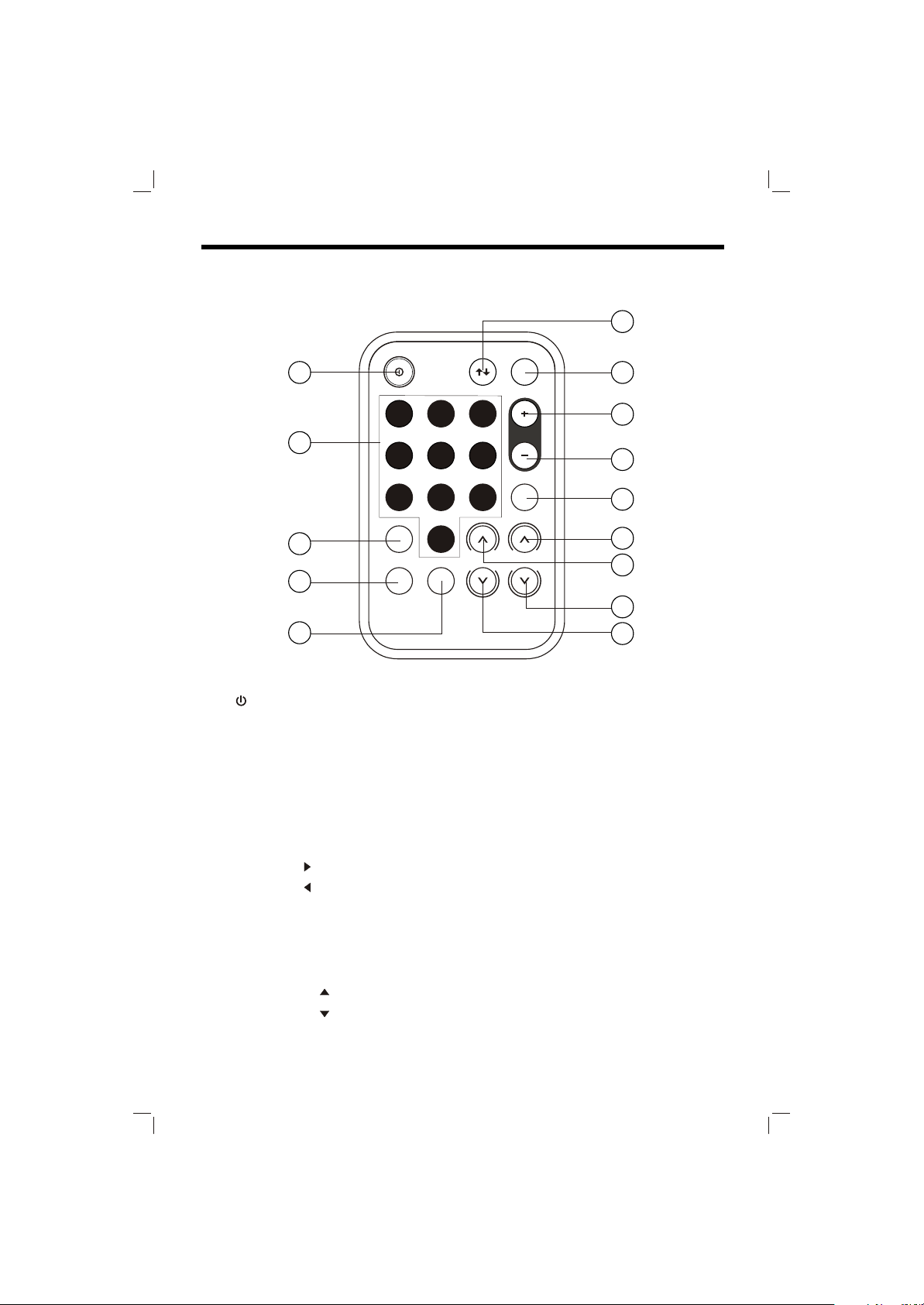
1. /I POWER
2. OPEN/CLOSE
3. IR
4. AUDIO IN (AV1)
5. VIDEO IN (AV1)
6. 6.5 inch MULTI COLOR TFT
MONITOR
7. Reset
8. VOLUME
9. VOLUME
10. MENU
11. TV/AV
12. AUTO
13. IR
14. CHANNEL
15. CHANNEL
16. 4:3/16:9 Selector
19
21
22
23
26
24
27
25
17. POWER
18. OPEN/CLOSE
19. TV/AV
20. 0~9 Numeric buttons
21. ANGLE+
22. ANGLE-
23. AUTO
24. VOLUME
25. VOLUME
26. CHANNEL
27. CHANNEL
28. -/--
29. DSP
30. MENU
^
^
^
^
9
Page 10

OPERATION
SWITCHING ON/OFF THE UNIT
Switch on the unit by pressing POWER
button (1) on the front panel or POWER
button (17) on the remote control. When
system is on, press it again to turn the
unit off.
OPEN/CLOSE THE MONITOR AND
ANGLE ADJUSTMENT
Press OPEN/CLOSE button (2) on the
front panel or point the remote control
to IR (3) on the front panel and press
OPEN/CLOSE button (18), the
monitor will stretch automatically.
OPEN/CLOSE button
Fig.1
When the monitor stretches to a certain
location, it will turn upward
automatically and stop at vertical
position.
Fig.2
Adjusting the viewing angle.
When the monitor doesn't move, you
can press ANGLE+ button (21) or
ANGLE button (22) on the remote
control to turn the monitor upward or
downward at fine steps to get a
desired viewing angle. And you can
rotate the monitor left and right from
the central viewing position at a
certain angle range manually.
Don't rotate the monitor forcibly to
avoid mechanical damage.
When the monitor turns downward to a
certain angle, it will draw in.
There is a remote sensor IR (3) on the
front panel. On the monitor, there is
another remote sensor IR (13) to receive
remote control signal. You can point the
remote control handset to IR (3) (when
the monitor doesn't stretch out) or IR (13)
(when the monitor stretches out) and
press function keys on the remote control
to control the TV unit.
The unit is also connected to an external
remote receiver (See the electrical
connection diagrams on Page 7), and the
function is the same with IR (3) and (13).
10
Fig.3
Return the monitor to the central
viewing position, then press
OPEN/CLOSE button (2) on the
front panel or press OPEN/CLOSE
button (18) on the remote control,
the monitor will turn downward
automatically.
Fig.4
Fig.5
REMOTE SENSOR
Page 11

OPERATION
Notes:
The external remote receiver is placed
near the monitor for the best to receiver
remote signal easily.
If the angle of the monitor from vertical
exceeds 20 (Especially the distance
exceeds 3m.), controlling the TV
through IR (3) or (13) cannot get good
effect. You are suggested to use the
external remote receiver.
6.5 inch TFT DISPLAY
When the monitor stretches out, the 6.5
inch color TFT display (6) can show the
current state of the unit.
RESET FUNCTION
Reset button (7) must be activated with
either a ballpoint pen or thin metal object.
The reset button is to be activated for the
following reasons:
Initial installation of the unit when all
wiring is completed.
All the function buttons do not
operate.
Error symbol on the display.
Note: When the monitor stretches out and
on the central viewing position, activate
the reset button (7), the monitor will turn
downward and draw in automatically.
0
Menu Function
Press MENU button (10) on the front
panel or MENU button (30) on the
remote control, the menu will show
on the display (6).
(For the unit with NTSC system):
Press CHANNEL button (15) or
CHANNEL (27) button on
remote control to choose channel
downward.
The numeric buttons (0,1~9) (20)
allow you to select the
corresponding channel directly.
Press digital select button (-/--) ()
cooperatively used with numeric
buttons to select channel desired.
For example, when you want select
16 channel, press -/-- (28) to switch
between "-" and "--", when the "--"
appears on the display, you can
press "1" button then press "6"
button to select 16 channel.
MENU
TV OPERATION
When the monitor stretches out, you can
operate the unit by using the current
menu displayed on the 6.5 inch color TFT
display (6).
Selecting receiving mode
In TV mode, press TV/AV button (11)
on the monitor panel or TV/AV button
(19) on the remote control to select
among TV/ AV1/AV2/RGB. The
corresponding state will show on the
TFT display (5).
Selecting channel
Press CHANNEL button (14)
on the front panel or CHANNEL
(26) button on remote control to
choose channel upward and or
^
Press CHANNEL / (14&15) on
the front panel or CHANNEL /
buttons (26&27) on the remote
control to select the item upward or
downward. Then press VOLUME /
(8&9) on the front panel or
VOLUME / buttons (24&25) on
the remote control to adjust the
selected item. The corresponding
value will show on the display.
11
^
^
^
^
Page 12

OPERATION
Auto Searching channels
Press AUTO button (12) on the
monitor panel or AUTO button (23)
on the remote control to enter into
auto searching mode, then press
CHANNEL button (14) on the
monitor panel or CHANNEL button
(26) on remote control t to start
searching TV channels. Then press
CHANNEL button (15) on the
monitor panel for about one seconds
or press CHANNEL button (27) on
the remote control to stop searching.
Volume adjustment
Press VOLUME / buttons (8&9) or
VOLUME / buttons (24&25) to
adjust volume level.
^
^
Screen display
Press DSP button (29) on remote
control to display the current status
such as TVch /AV1/AV2. If you don't
operate for over 5 seconds, the
information on the screen will
disappear.
^
^
4:3/16:9 Selector
Slide the 4:3/16:9 switch (16) on the
monitor panel to select appropriate
TV aspect (4:3 or 16:9).
SPECIFICATION
GENERAL
Power Supply Requirements: : DC 12 Volts, Negative Ground
TV
Monitor Screen Size : 6.5"TFT
Resolution : 1440x234 dots
TV Sensitivity : 40dB
12
Page 13

www.pyleaudio.com
88-T1990-02
 Loading...