

Page 1
VIDEOVIDEO
PLDTVN65
Page 2
Page 3
Page 4

It is prohibited in law if you watch TV or other multimedia
programs while driving. So for your safety, please do not watch
programsor operate the instruments.
The system is designed to aid you to back cars, we will not take
Any responsibility if there is an accident when backing.
There is laser in CD changer. There will be possibly an exposure
of harmful laser if try to operate or adjust or make a
performance control.
Do not open the CD changer or try to make any change. It is
very complicated, and it uses laser adapter to read information
out of CD surface. Try to avoid the laser because of it is still
there.
Page 5

Brief Introduction
Thank you for purchasing this series of high quality AV products for automobiles. This
product is a multi-function system developed by our company and special for high-level
cars, business vehicles and special-use vehicles and has a car-carried control center
concentrating entertainment, audio-visual, radar distance test, rear view and TV as a whole.
This product also adopts professional car-carried suck-up DVD chip and can play DVD,
MP3, VCD and CD. With high sensitive TV module, you can enjoy the every convenience
brought by TV, know the world news and stock increase & decrease at any time and
anywhere. This machine can control disc exchanger of CD & DVD, 50W car-carried
special power amplifier and FM/AM digital tuning radio, providing satisfactory AV
entertainment for the customers. It uses 6.5” LCD display with 16:9 proportion suitable for
people's eyes, which has very wide visual angle in upper & down, left & right and its
structural dimensions conforming with the mounting dimension of ISO TWO Din.
This system bears the professional design of car-carrier products, intelligence of all the
operations, and OSD menu display. And all the set parameters and location have automatic
memory and can restore automatically. It also has video input/output interface and carbacking visual input to show the information at car backing automatically. Professional
radar distance test module can be used alternatively, which makes the monitoring and
entertainment be done at the same time and frees you of apprehensions in the rear. Wide
band voltage design is applicable to the requirements of all types of automobiles. In order
to correctly install and use this product, please read this manual attentively.
Characteristics
2.1 Specifications
2.1.1 System parameters
Items
V oltage
Current
Working Temp.
Store Temp.
Video system
Inputs
Sizes
Parameters
DC 11V-14V
1.5A Amplifier off MAX 10
-10 60
-30 80
Auto PAL or NTSC
One channels of video input/backing lens input
(Comprise one channel of back running video)
178(W) 176(L) 100(H) mm
-1-
Page 6

Weight
Screen size
Resolution
Dot pitch
2.1.2 Performance parameters
2.6 kg
16:9 6.5 inches diagonal
1200 234 pixels
0.136(H) 0.416(V)
Items
FM/AM modulation parameters
Modulation
Display
Memory capacity
Seeking
Band
Receive System
Seeking
Memory method
Memory capacity
Antenna resistance
V oltage
Current
Audio output Vol.
Output tracks
Output resistance
Frequency response
SNR
CD Changer Dims
CD Changer weight
Disc box weight
Disc box capacity
Parameters
FM:87.5-108MHz AM:522 1611Mhz
Phase-locked loop frequency modulation
Panel LCD or OSD
FM:16 AM:8
Automatic/by hand
TV parameters
VHF-L 48.25 170.00MHz
VHF-H 170.00 450.00MHz
UHF 450.00 863.25MHz
PAL /NTSC
Automatic/manual
Automatic
40 channels
75
CD parameters
11 14V
< 1A
2 Vpp
2 tracks (R L)
600
5 20000Hz ( 1dB)
96 dB
230(L) 69.5(H) 164.5(W)mm
1.5Kg
0.17Kg
8 16 discs(8 discs Panasonic DP88 /12 disc)
-2-
Page 7

Video output 1 Vpp
Video system
Dynamic area
Distortion
Definition
TV system
Test voltage
Maximum power output
Full power output
Speaker resistance
Tone
2.2 Functions
Disc
SNR
VCD parameters
DVD parameters
12cm DVD/VCD/CDMP3/CD-R
>90 dB
>90 dB
<0.05%
>500
PAL/NTSC
Amplifier parameters
13.8V
50W 4 4
25W 4 4
4 can be 4 8
Bass
Treble
100Hz 12dB
10kHz 12dB
NTSC (default) or PAL
Built-in function: in car DVD, 50W amplifier, DVD, VCD, CD,MP3,CD-R
TV: Build in TV function, 40 channels restorable
AM/FM receiver: 24 stations restorable
Radar measure: radar measuring back sight system (optional)
Monitor: introduce 16:9 6.5 inch TFT LCD monitor
Automatic memory: All set characteristics and positions can be remembered
automatically, and can be restored automatically.
Display system: AUTO PAL or NTSC.
Remote controller: remote controller can fulfill all function.
Menu function: OSD menu can indicate all operations, and real-time is also available.
Signal sources: AV input/output (comprise one channel of back running input).
Back running detection: This system has back running video input, the input system
Will be switched to back running input to monitor the back running process.
-3-
Page 8

System Installation
3.1 Installation key points
The product is specially designed for 12V vehicle, if installed in other vehicles, please
install power Changer.
To avoid short-circuit, it is strongly suggested to disconnect accumulator cathode before
installation.
This product should not be used without fuse.
Do not connect with the mains directly with that of other electrical equipments.
Do connect the ACC & BATT cord according to the installation instruction, or the
instrument will automatically power off abnormally. And please remember to switch off
the power supply after usage, or it will consume lot of the stored battery.
The installation position should be chose in a place which will not effect the
Operation of other electronic instruments, such as air-conditioner.
3.2 Host equipment installation
Pay attention not to destroy or dirty instrument desk.
Find a free slot in the instrument desk, clean up the inside for enough space.
insert DVD player in the slot.
Take out the host equipment and connect to power supply jack, video jack.
Please refer to CD changer installation instruction.(Refer to 11.2)
3.3Connection
Connect power cord ACC (red) to ignition switch.
Connect BATT (yellow) to the circuit of accumulator.
Connect back running cable (blue) to back running switch or back running lamp
Circuit (12V is valid)
Connect antenna and amplifier control cable.
Connect all video cable to video inputs.
Connect speakers to amplifier outputs (pay attention to color and polarity)
Plug antenna-to-antenna jack.
Connect CD changer control line (referring to CD changer installation)
Check all connections.
Clean up all cables for installation
-4-
Page 9

3.3.1 System connection diagram
Audio output (FR Red)
Video output (yellow)
Audio output (RR Red)
Audio output (RL White)
Radio antenna input
TV antenna input
Audio output (FL White)
With build-in Dolby
digital, DTS or
MPEG decoder
AV Audio input R (Red)
AV Video input (Yellow)
VCD changer Cable
CD Audio input R (Red)
AV Audio input L (White)
CD Audio input L (White)
:
:
:
Yellow: Video
Red: Right channel
White: Left channel
1\Antenna control is height effective
2\Amplifier control is height effective
Caution:
3\Cassette should be grounded
VCD output
GND
DVD
VCD changer
Red CD AUDIO OUTPUT/R
White CD AUDIO OUTPUT/L
Lens Input
Left Back
Radar Input (Optional)
Right Front
Green
Green/Black
Left Front
Gray
Gray/Black
Right Back
White/Black
White
Purple/Black
Purple
BACK Blue
GND Black
ACC Red
BATT+ Y ellow
BRAKE Blue/white
A/P Green
-5-
Page 10

, Introduction to buttons
4.1 Buttons on monitor panel
RADIO
AV
MODE
SET
Radio Play
1
2
CDC Play/Switch Display Data
3
DVD Play/Switch Display Data
TV Select
4
AV Select
5
6
Switch Power/LCD Angle Adjust
7
Last Track/Last Station
8
Next Track/Next Station
9
Reverse/Frequency fine tune(-)
10
Fast forward/Frequency Fine tune(+)
BAND
DVDS
S
M
MUTE
Tract Switch/Band Select
11
12
Title Select/Last Disc
Language Select/Next Disc
13
Back to Main Menu(DVD)
14
Mute
15
16
DVD Setup
17
System Setup
18
Setup Control
Volume(Down)
19
20
Audio Control Switch
Volume(Up)
21
-6-
Page 11
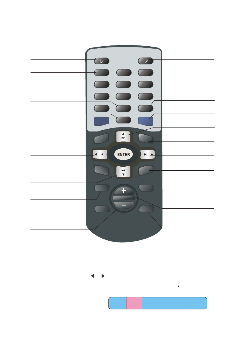
4.2 Remote controller button functions
LCD Angle adjust(-)
Number buttons
DVD Language Select
Band/Track Switch
Manual Memory/DVD Setup
OSD Switch
Last Track
/Last Station/Left
(DVD) Last Track
Reverse/Frequency fine
tune Down
Signal Source Select
System Setup
1
1
4
7
0
MEMORY
SD
O
PR
E
Source
Setup
LCD ANGLE
2
5
8
Language
L/R
BAND
Title
Seek
ME
NE
3
6
9
N
X
Mode
Mute
LCD Angle adjust(+)
DVD/Title
Self-search
Fast forward/Frequency
Fine tune(+)/Up
U
DVD Main Menu
Next Track
/Next Station/Right
(DVD) Next Track
T
Audio Control Switch
Volume Adjust(+)
Volume Adjust(-)
Mute
4.2.1 Signal source selection
Press the signal source selection key SOURCE on the remote board, the screen will display
as the following picture, use or for switch, and press ENTER for confirmation of
entering into the corresponding play mode (AV/CDC/TV/DVD/RADIO)
AV TV DVD RADIOAV TV DVD RADIOAV TV DVD RADIOAV TV DVD RADIOCDCCDCCDCCDC
-7-
Page 12
System operation instruction
5.1 Turn off /start system
Press key (>2S) for 1 second to turn off the power of the system, pressing it once again
will start the system automatically and restore to the last used status.
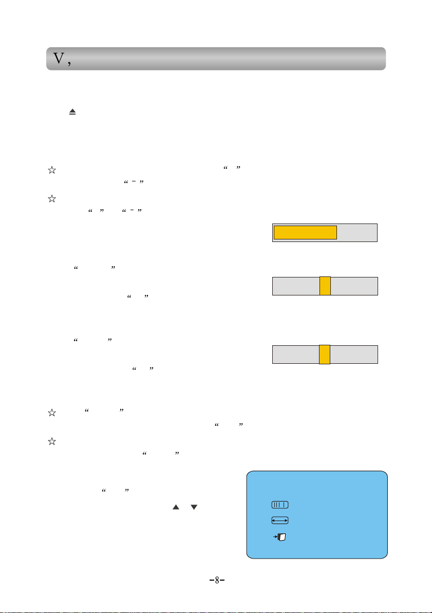
5.2 Volume control
In the volume adjusting mode, press key + , the volume will get louder and get
weaker when press .
The volume during adjustment will be displayed on the screen (min. 0, max.31),
press key + or Continuously, the volume
Can be adjusted continuously, see the right picture.
5.2.1 Bass adjustment
Volume: 16
Press MODE until the bass-adjusting mode is got,
the screen will display as the right picture, then adjust the
bass effect with key +/- .
Bass : 0
5.2.2 Treble adjustment
Press MODE until the treble adjusting mode is got,
the screen will display as the right picture, then adjust the
treble effect with key +/- .
Treble : 0
5.2.3 Mute
Press MUTE to shut down the sound, and the system will go into no-sound mode,
MUTE will display on the screen. Press UTE once again to leave the mute mode.
The volume still can be adjusted under the mute mode, but system is still in no-sound
status. Only pressing MUTE again can restore to the sound mode.
5.3 System setup
Press button SET in any mode, the screen will
display as the right picture, or (18) up and
down to select LCD SETP (LCD Screen Setup).
BALANCE (balance adjustment up and down, right
and left.).
SYS SETP (System Setup), the selected menu will become pink.
press
LCD SETP
BALANCE
SYS SETP
Page 13
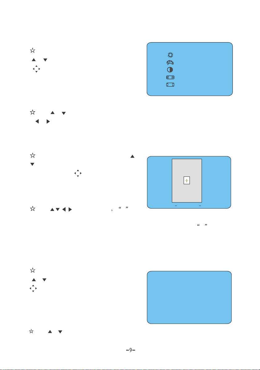
5.3.1 LCD Screen Setup
Press SET to enter into menu setup, press
(18) t
or o select LCD screen setup, press
(18)
setup.
The screen will display as the right picture.
vertically to confirm into LCD screen
BRIGHT :32
BRIGHT :32
COLOUR:22
COLOUR:22
CONTR :25
CONTR :25
ANGLE :30
ANGLE :30
VIEW :WIDE
VIEW :WIDE
The setup of brightness, color, contrast,
angle and screen view (wide/zoom/center) can be done respectively.
s or (18 k. Press
Pres ) to select up and down, the selected menu will become pin
or (18
)to make setup. Press SET again to exit system setup.
5.3.2 Balance adjustment up and down, right and left.
Press SET to enter into menu setup, press or
(18) to
Right & Left. press vertically to confirm
entering into Balance Adjustment Up &Down,
Right & Left. The screen will display as the right
picture.
move up and down, right and left to control the volume of the four channels up and down,
right and left. The volume of the four channels will be the same when + is in the
middle. Press SET again to exit system setup
select Balance Adjustment Up &Down,
(18)
(18)
Press respectively + will
Front
L
Rear
L
BALANCE
Front
R
Rear
R
5.3.3 System setup
Press SET to enter into system setup. Press
(18)
or to select System Setup, press
(18)
setup mode. The screen will display as the right
picture. The blue screen, beep, car-backing, view
switch, time displaying and time adjustment can
be set up respectively.
Press or select up and down, and the selected menu will become pink; press
vertically to confirm entering into system
(18) to
SYS SETUP
SYS SETUP
BLUE :ON OFF
BEE :ON OFF
BACK:ON OFF
TIME :ON OFF
TIME :ADJ
Page 14
Or (18) to make setup. Press SET again to exit System
Note: When the blue screen is set to ON , and no visual signal is input, the
screen will display in blue.
5.4 Time setting
Press SET to go into System Setup (refer to 5.3.3 in detail),
and select TIME ADJ, press (18) vertically to confirm
entering into time setup mode. The screen will display as the
right picture.
TIME
12:00
ADJ
Press or (18) for time adjusting, press or (18) for change-over selection between
HOUR and MINUTE. Press vertically after that to confirm and store the time setup,
also return to System Setup.
Press SET directly to exit without storing the setup.
5.5 Monitor angle adjust
When the system is ON , short pressing can adjust the display angle to the
preset angle or return to vertical mode.
A.When the system is under non-DVD mode, the display angle status can be
vertical preset angle;
B.When the system is under DVD mode, the display angle status can be vertical
preset angle max. angle.
When the system is ON , pressing on the remote board can tune the
display angel to bigger or smaller;
The preset angle of the display can be set in the System Menu (refer to 5.3.1),
under non-DVD mode, or also can be used to preset angle.
Radio operation
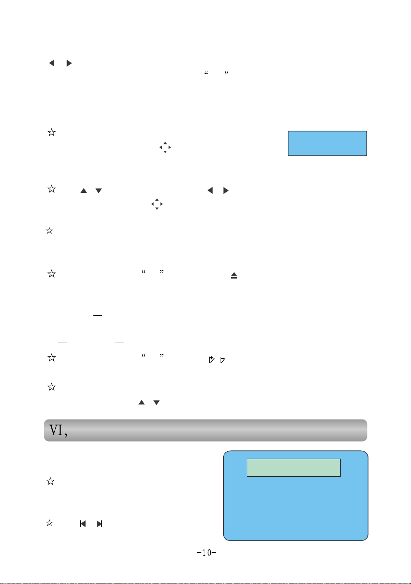
6.1 Receive pre-stored stations
Press RADIO to enter into radio mode
and play back the pre-stored radio channels,
please see the right picture.
Press or to play the pre-stored last or
next radio channel;
RADIO
FM - - M2
FM - - M2
90.6MHz
M1 M2 M3 M4 M5 M6 M7 M8M1 M2 M3 M4 M5 M6 M7 M8
Page 15
Press the digital keys (1~8) on the remote board, directly play the corresponding
pre-stored radio channel;
Volume adjusting please refer to 5.2;
Select other functions(AV,TV,DVD,CDC) to stop playing radio.
6.2 Frequency Switch
Press button BAND, you can choose FM(FM1/FM2) and AM.
6.3 Searching station
A.Manual search
Press or , tune the radio frequency forward and backward by 0.05MHz
each step;
Pressing (>2S) or longer will initiate the automatic search or last/next
radio channel; press SEEK or reverse search key to end manual search. The
current receiving frequency will be displayed on the screen.
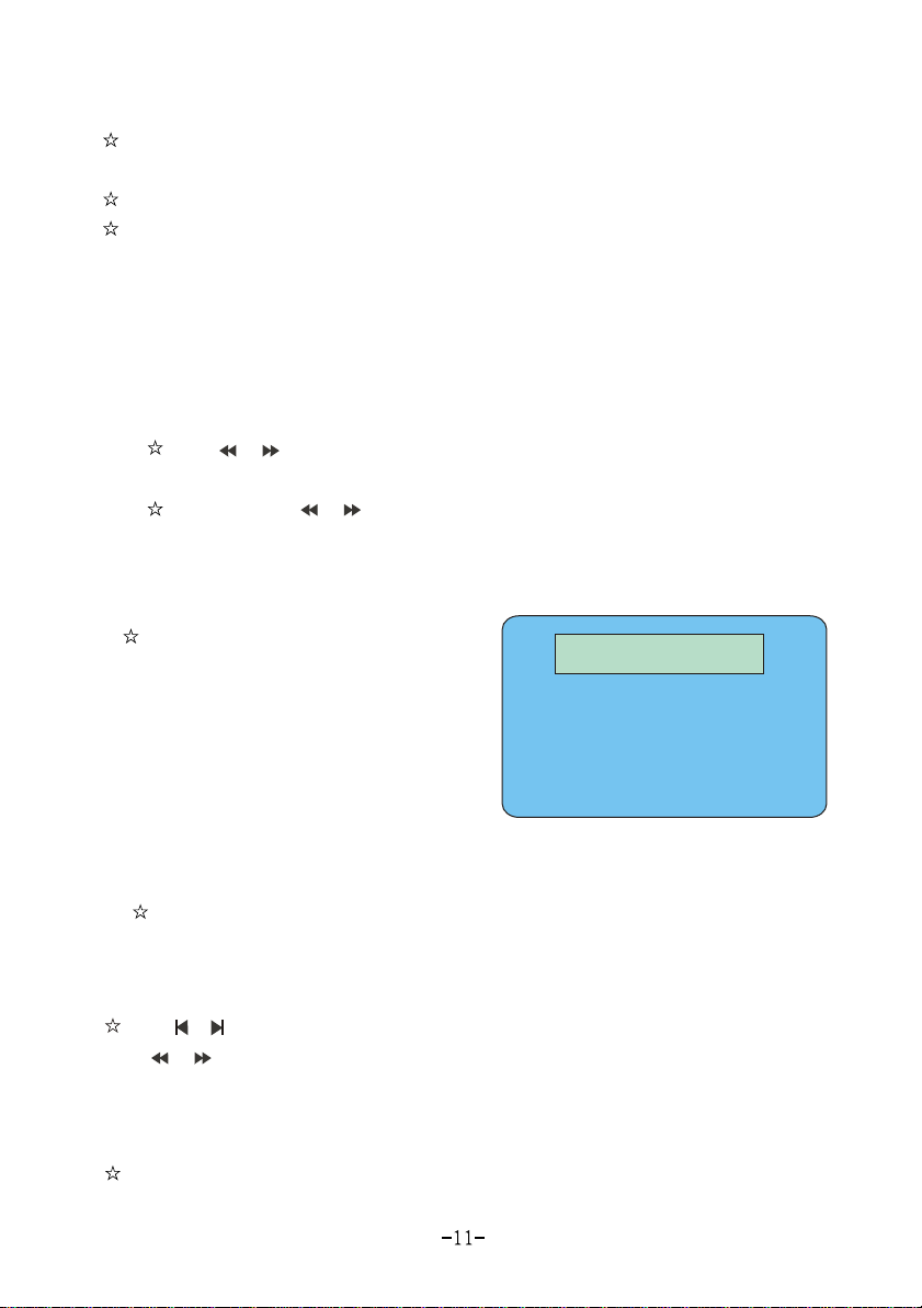
B.Automatic search
Pressing SEEK two times continuously
(3S)under receiving status will enter into
automatic search mode. Search for all the
radio channels within the frequency in
order and store automatically. During the
search, the changed frequency will be
displayed on the screen.
After the search ends, the first searched channel will be played automatically and
the current receiving frequency will be displayed on the screen.
Pressing SEEK under the automatic search mode will end the automatic
search and return to receiving status.
M1 M2 M3 M4 M5 M6 M7 M8M1 M2 M3 M4 M5 M6 M7 M8
RADIO
FM - - Seek
FM - - Seek
90.6MHz
6.4 Store station manually
Press or to select the radio channel No. (M1~M8) you want to store, then again
Press or to manually search the radio frequency you want (refer to 6.3 in detail).
When the radio channel has been found, press M, making the radio No. you want to
store blinking and pressing M button once more in 3 seconds, which will store the
radio channel into the corresponding Number
This system can contains 24 preset channels, and store 8 channels of FM1, Fm2 And
AM respectively.
Page 16
,TV operation
7.1 TV play
Press TV button to start TV signal receiving.
Volume adjust refer to 5.2
Select other function( AV\Radio\DVD\CDC) to stop playing TV.
7.2 Receive preset TV stations
Press TV button to watch TV, press or for playing preset next TV station
or last TV station.
Press number button(0-9) system will switch to that TV station after 3 seconds.
Press button(0-4), screen will display X , press once again the button
within 3 seconds, system will switch to XX channel automatically.
The numbers of TV station depend on the TV signal.
This unit can store 40 channels.
7.3 TV channel selection and adjustment
A.Automatic search
Press SEEK two times continuously (3S)
under the TV playing status to enter into TV
channel automatic search mode. Search for all the
TV channels within the frequency in order and
store automatically. After the search ends, the first searched TV channel will be
played automatically.
Pressing SEEK under the automatic search mode will end the automatic search
and return to the playing status.
B.Tuning
Press or , tune the TV frequency forward and backward by 50KHz ;
C.Store the TV stations manually.
Press or to select the TV channel No., then Press or again to manually
search the TV frequency you want . When the TV channel has been found, press M,
TV SEEK
VHF: L
Page 17
making the TV channel No. you want to store blinking and pressing M once again in
3 seconds, which will store the TV channel into the corresponding Number.
This machine can pre-store 40 channels.
, DVD operation
8.1 DVD playing
Press key DVD, play DVD. Press DVD again or press OSD on the remote board
to change to display OSD information.
Press key M or TITLE on the remote rod to select captions.
Press key S or LANGUAGE on the remote rod to select language.
Press key A to return to DVD playing menu.
During playing, press (18) to pause DVD playing , press it again to leave
pause status.
Press key DVD to enter or exit DVD setup (DVD will pause playing when
entering into DVD setup).
Select other functions (AV, TV, Radio, CDC)to stop DVD playing.
8.2 Changing song
Under DVD playing status, press or to choose last or next track.
Under DVD playing status, press PRE on the remote board to last track,
press NEXT to next track.
8.3 Fast forward/reverse
Press or button for fast forward or reverse.
Press button for backing to normal playing state.
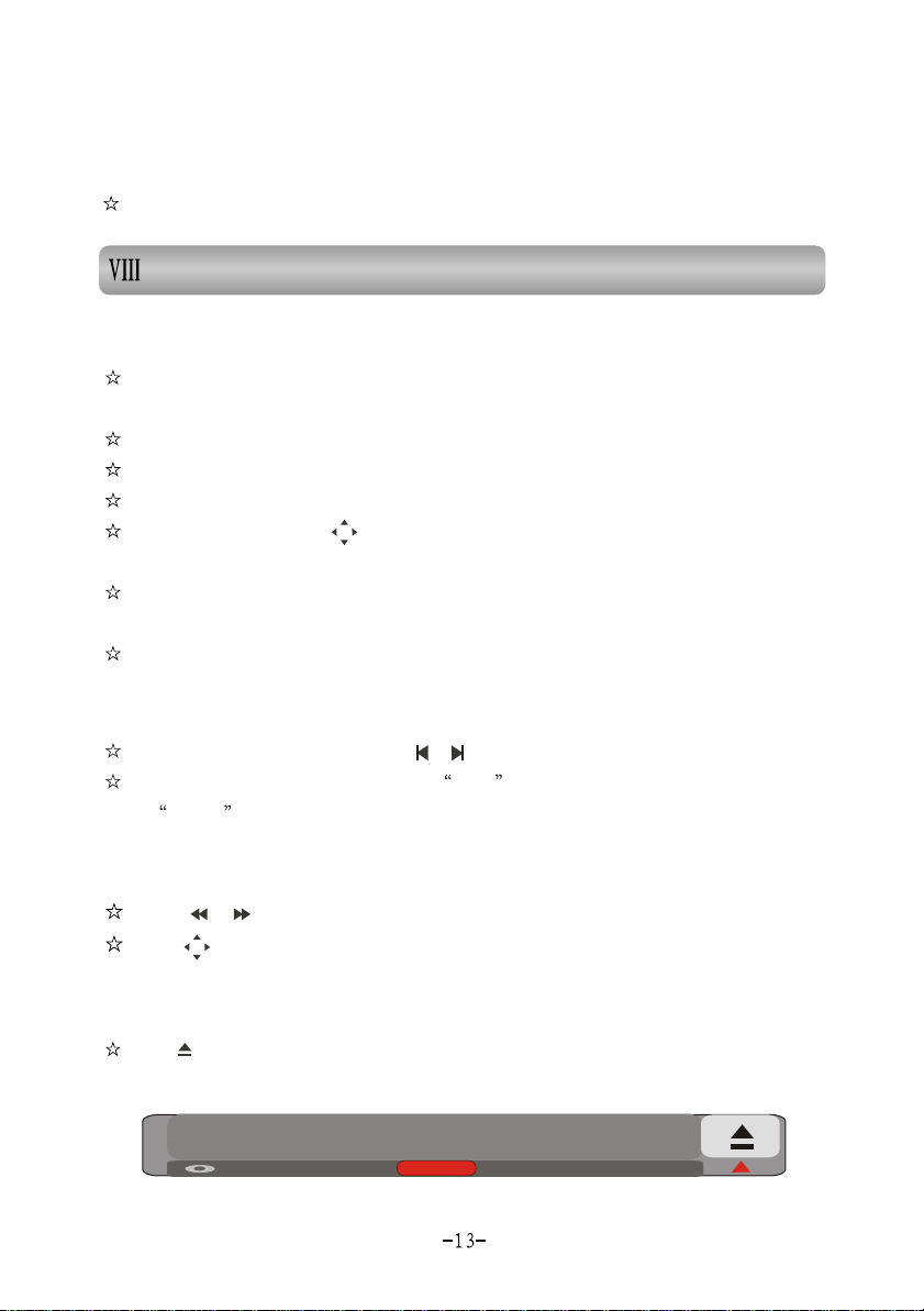
8.4 Changing disc
Press to adjust the screen to the max. angle and reveal the disc ejection window, as
shown in the following picture. Press again the on the DVD window to eject the DVD disc.
DISC
Note: When the indicator of the disc case is ON, it means a disc is inside the DVD case.
Page 18

8.5 Track switch
Under DVD mode, press BAND to change the sound channel. There are 3 selections
(L/L, R/R, L/R) for sound channel change; the sound channel status will be displayed
on the screen. If it is stereo(L/R) , the display will disappear after 3 seconds.
, CDC operation
9.1 CDC playing
Press key CDC, play CDC. Press CDC again or press OSD on the remote board to
change to display OSD information.
Select other functions (AV, TV, Radio, DVD)to stop CDC playing.
9.2 Changing song
Under CDC playing status, press or to select last or next track.
9.3 Fast forward and reverse
9.3 Fast forward and reverse9.3 Fast forward and reverse
Press or continuously to make disc go forward or reverse fast, release them to
end the fast forward or reverse and restore to the normal playing status.
9.4 Changing disc
Manual change
A.
Press key M or S to play the last or next disc;
Press the digital keys to play the disc in the corresponding case.
Automatic change
B.
The system will change the disc automatically after the playing of one disc has
ended.
9.5 Track switch
Under CDC mode, press BAND to change the sound channel. There are 3
selections (L/L, R/R, L/R) for sound channel change, the sound channel status will be
displayed on the screen. If it is stereo (L/R), the display will disappear after 3 seconds.
Page 19
9.6 CD changer operation
9.6.1 Insert discs
Place the box with the side which has CD symbol upward. Draw out plate one by one
to stop positions.
Place discs on the plates in sequence.
Push forward the plates into box until you hear a sound of click.
To avoid accidental failure, place only one disc on one plate.
9.6.2 Remove discs
Draw out disc plates out of CD changer to stop position, take out of discs with hands.
Take CD changer with care, if the disc insertion
position faces downward, there may be a risk of slipping
disc out of plates.
9.6.3 Insert disc box
Glide the door leftward until the door is opened widely with a sound of click.
Check equipment top and the direction of disc insertion, push CD changer inside
gently until a sound of click.
Close door until you hear a sound of click.
Make sure to close CD changer
door closely to prevent dusty enter.
9.6.4 Remove disc box
Screw ignition key turn on receiver power.
Open glide door.
Press ejection button , CD changer will be ejected out.
Draw out CD changer according to arrow direction, until CD changer glides out of
equipment.
Page 20

CAUTION: If in any case, the CD changer can not be draw out, press RESET
button and push the CD changer inside with strength, then press ejection button .
, AV operation
10.1 AV play
Press AV button, start playing AV
select other function(TV Radio DVD CDC),stop playing AV.
Note: The AV input channel is commonly used with car-backing scene,
if you use AV function, please set the BACK in Sys Setup to OFF (refer
to 5.3.3 in detail) .
10.2 Backing with backsight
If you want to use the rear-view function at backing, please set BACK in Sys Setup
to ON (refer to 5.3.3 in detail). If the AV interface loses efficacy, the signal can not be
input.
When the car converters into BACK, no matter what condition the system is in, it
will automatically transfer to back view display, the screen will display BACK (car
backing signal input). After leaving the BACK mode, all the functions of the system
will restore automatically.
Page 21
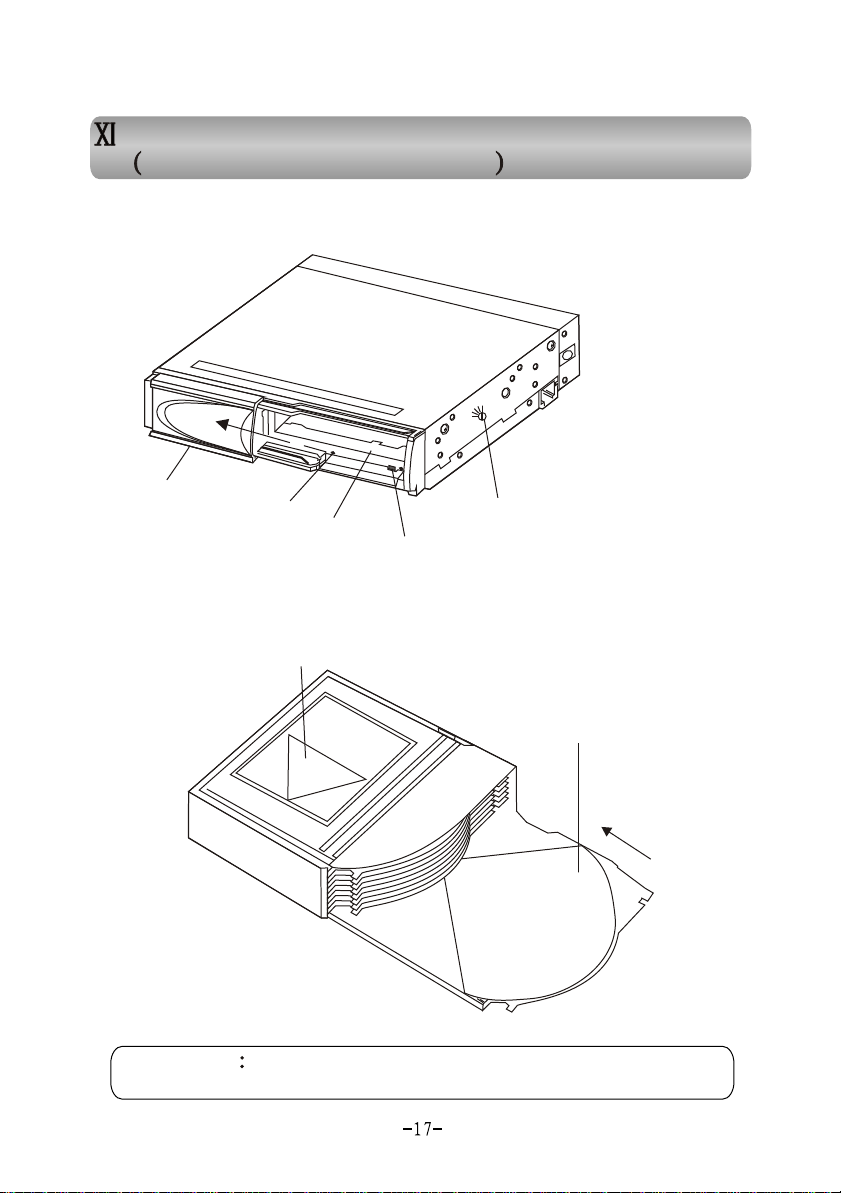
, Necessary Disc machine installation
, Necessary Disc machine installation
In Example of Panasonic DP88
In Example of Panasonic DP88
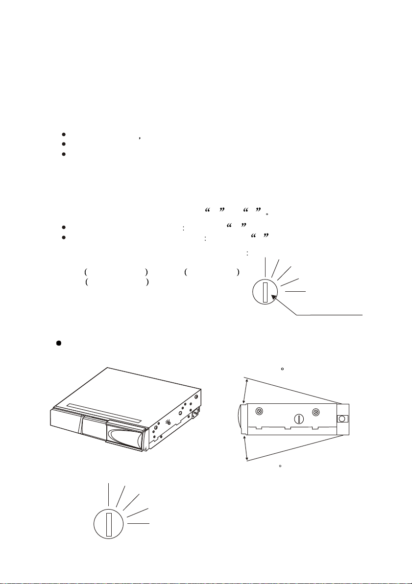
11.1 Appearance
11.1 Appearance
11.1.1 CD changer
11.1.1 CD changer
H H
A A
B B
CC
VV
Door
Reset
Compact disc area
Eject
Angel Adjust Screw
There are two angel adjust
screws for both sides.
11.1.2 Compact disc and tray11.1.2 Compact disc and tray
Compact disc inserting direction
IO
IO
D
D
U
U
c
c
L A
L A
A
A
T
T
CT
CT
is
is
IGI
IGI
A
A
P
P
D
D
OM
OM
C
C
D
D
CAUTION Do not use a disc with 8cm diameter. Tray should
CAUTION Do not use a disc with 8cm diameter. Tray should
be placed in the right position before inserting compact disc.
be placed in the right position before inserting compact disc.
Tray
Page 22
11.2 Installation guidance
11.2 Installation guidance
11.2.1 Installation location
11.2.1 Installation location
When the temperature in car is too high, do not install this instrument on rear
undercarriage to avoid the problems, in case it is caused by the contact with it. The
following locations also should be avoided,
Direct sunshine hot air from heater or other high temperature places.
Not safe or heavily vibration.
Too much humid, dirty or dusty.
11.2.2 Installation work11.2.2 Installation work
According to your selected installation angle, use a screwdriver to adjust the
angle-adjustment screw to a position of V or H
When set to vertical position Choose V position.
When set to horizontal position Choose H position.
H
This equipment has 5 positions for your choice
A)Horizontal b) Vertical
c) A 22.5 degrees d) B 45 degrees
e) C 67.5 degrees
The following data is for your reference in installation.
11.2.3 Installation angle
11.2.3 Installation angle
Horizontal installation
Horizontal installation
The instrument should be placed as follows.
The instrument should be placed as follows.
A
B
C
V
Angel Adjust Screw
<10 degrees
H H
A A
BB
C C
VV
HH
AA
<10 degrees
BB
CC
VV
Incline angle is less than 10 degrees.
(As shown in top figure.)
Place screws in same positions in both
sides (as shown in left figure).
-18-
Page 23
Vertical installationVertical installation
Vertical
installation as
shown below
Incline angel <10
degrees (as shown
below)
Place screws in same
positions in both sides
(as shown below)
<10 degrees
CC
VV
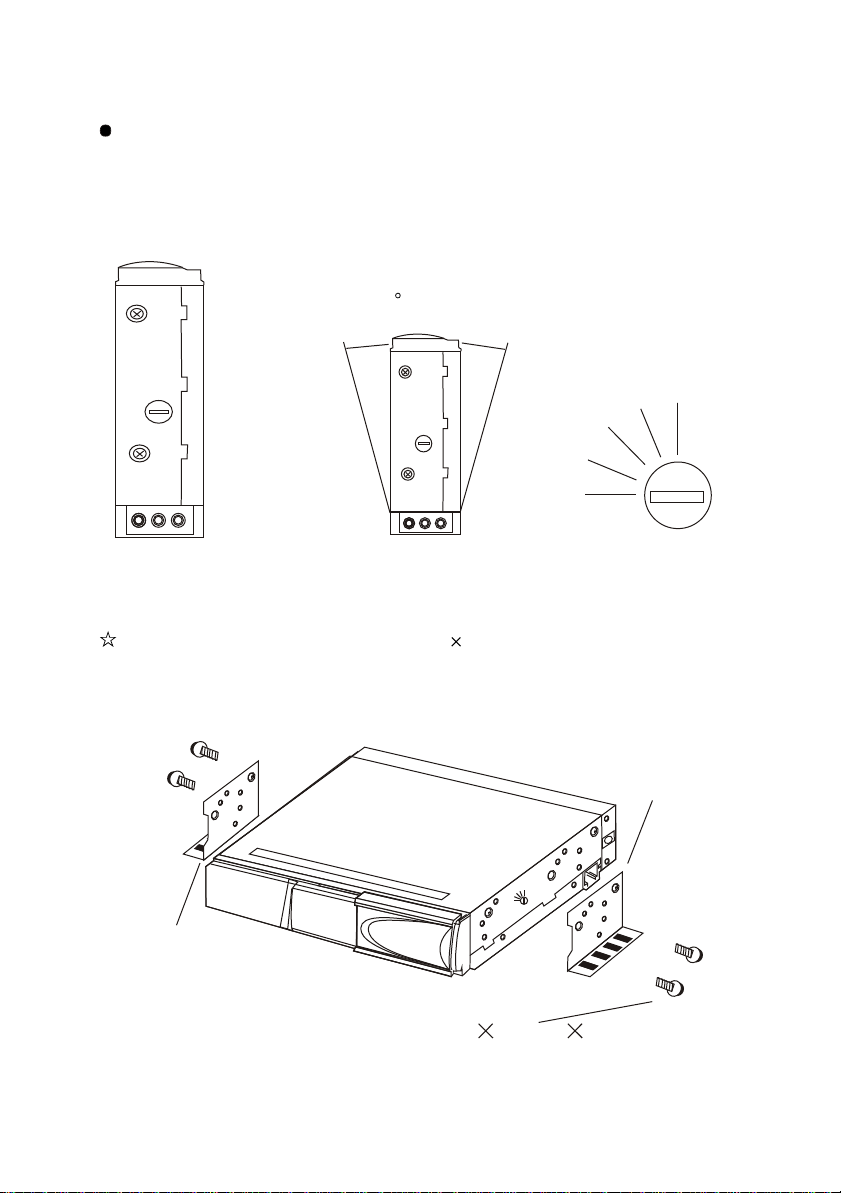
11.2.4 Typical horizontal installation11.2.4 Typical horizontal installation
Use a hexagonal bolt with 2 washers(M4 8mm)
Fix left and right installation trays onto host instrument.
HH
AA
BB
Left tray
H H
A A
B B
CC
VV
Hexagonal bolt with 2
washers(M4 8mm) 4
-19-
Right tray
Page 24
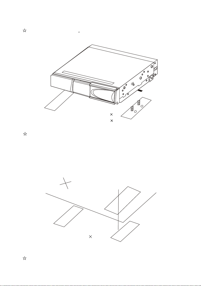
Choose position to install fix trays with double sided adhesive tape.
H H
A A
B B
CC
VV
Double sided
adhesive tape 2
Tray 2
Cut a small cross on carpet in the position, which is right towards the M5 bolt
on tray.
Tray 2
Fix both tray and tape onto installation plate under carpet.
-20-
Carpet
Page 25
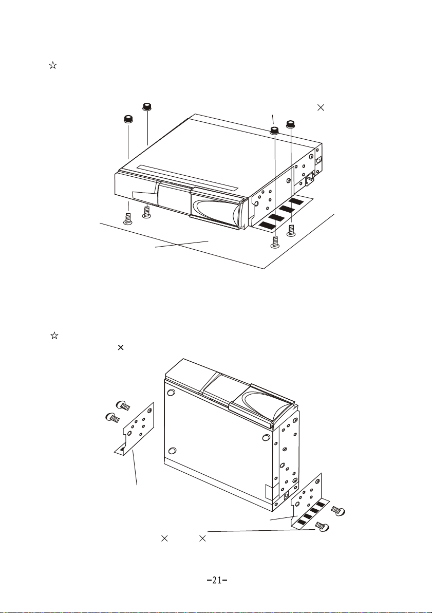
Use 4 hexagonal bolts(M5) to install the equipment onto the 4 holes on carpet.
AA
AA
BB
BB
CC
CC
VV
VV
HH
HH
(M5) 4
Exagonal bolts
Carpet
11.2.5 Typical vertical installation
Fix trays onto the both sides of equipment by using hexagonal bolt with 2
washers (M4 8mm)
Left tray
Hexagonal bolt with 2
washers(M4 8mm) 4
Right tray
Page 26
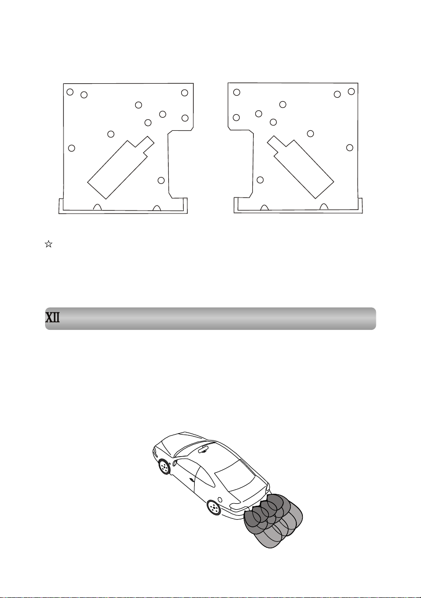
11.2.6 The relations between angles and installation holes.11.2.6 The relations between angles and installation holes.
HH
AA
BB
VV
Left tray
CC
CC
VV
CC
BB
AA
HH
Right tray
VV
BB
AA
CC
HH
BB
HH
VV
AA
The above figure has explained clearly the relation between installation
holes and installation tray (left and right) angles. There are marks that show
the installation angles. Please choose proper holes according to your
installation angle.
, Accessories, Accessories
Our products are in series; there will be slightly differences in functions and
accessories according to the specific specifications, for example, GPS and
backing camera. So for your own interests, please check all the accessories and
packing list.
12.1 Backing radar installation
12.1.1 Sensor's effective scope diagram
.
ea
ing ar
Brak
ow down area
Sl
ning
ar
W
-22-
area
Page 27
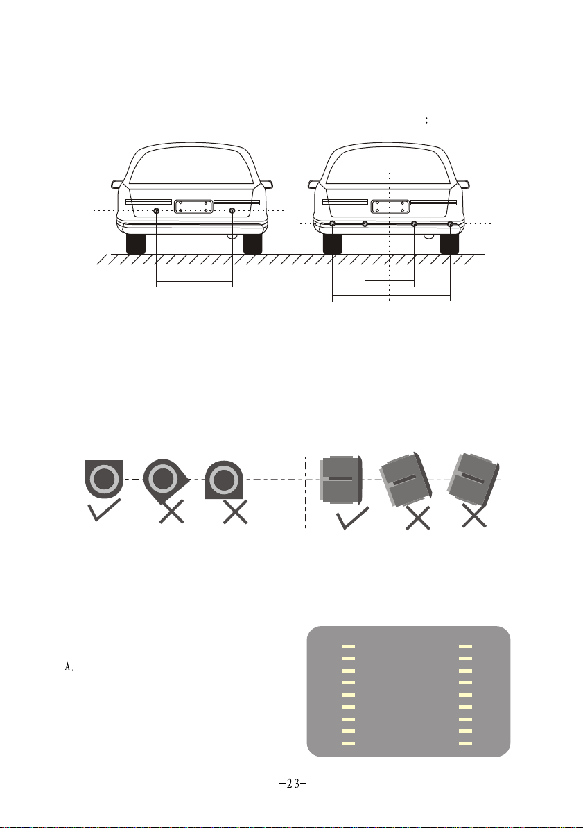
12.1.2 Sensor's installation position12.1.2 Sensor's installation position
According to the quantity installed, the positions can be as follows
60-80cm60-80cm
25cm25cm
63cm63cm
25cm25cm
63cm63cm
30-35cm30-35cm
30-35cm30-35cm
Remark: The final installation position can be adjusted slightly according to
The final installation position can be adjusted slightly according to
50-70cm50-70cm
you car dimensions.
12.1.3 the requirements and method of installation12.1.3 the requirements and method of installation
Sensors should be inserted vertically into rear bumper as the arrow's direction. Any
direction's inclination will affect the usage.
Vertical
Horizontal
12.2 Backing radar usage12.2 Backing radar usage
When backing car signal cable is connected properly, radar function will be started
automatically when you backing your car.
12.2.1 Signpost display12.2.1 Signpost display
NO-V
When radar is not connected,
Monitor can only display
ordinary signpost(yellow),
Which as shown in right picture.
Page 28
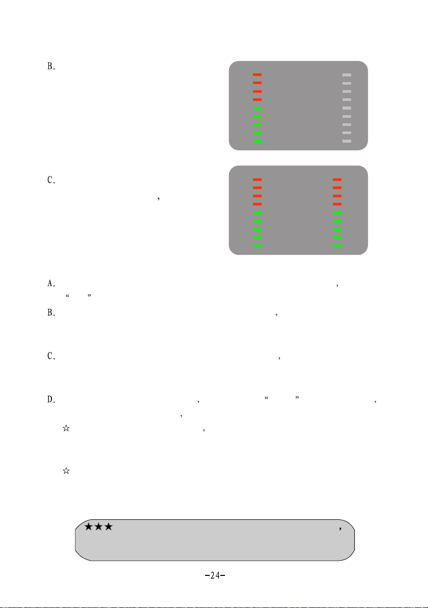
When radar backing car module
is connected and you only connect
left (right) sensor, monitor will only
display left (right) radar signpost,
and for right(left) (yellow), there
Is only ordinary signpost.
0.8M
When radar is connected, all
0.8M
sensors connected too monitor
will display radar signpost as
The right picture.
12.2.2 Display of radar detection12.2.2 Display of radar detection
When the distance between radar sensor and barrier is more than 1.6m there will
bea FAR on screen bottom.
When the distance is less than 1.6m but more than 1.2m the distance value will be
displayed on screen bottom and buzzer does not work. Sensor is now working in
warning area.
When the distance is less than 1.2m but more than 0.2m the distance is displayed
on the screen bottom and buzzer beeps, the more closer, the more frequent buzzer beeps.
Sensor is now working in slow down area.
When the distance is less than 0.2m it will display STOP! on screen bottom
buzzer gives out continuous sound sensor is now working in stop area.
When radar signpost is available with the decreasing of the distance between
radar sensor and barrier, red signpost goes down gradually. When the distance
increases, green signpost goes upward.
System takes out the data of four radar sensors, after calculation, the shortest
distance will be displayed on top of screen.
12.3.1 Precautions12.3.1 Precautions
The system is only designed to help you back your car
The system is only designed to help you back your car
our company will not take any responsibilities for any accident. So,
our company will not take any responsibilities for any accident. So,
please pay attention in driving.
please pay attention in driving.
Page 29
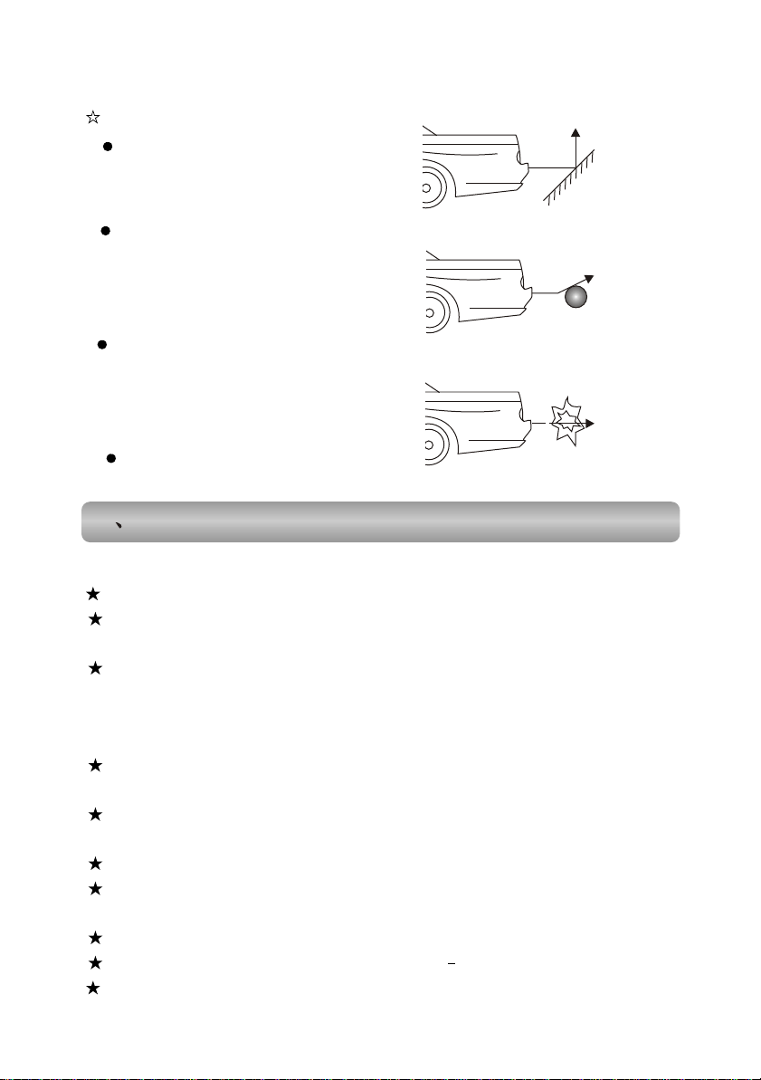
Detection can be affected by:
When in a smooth slope,
signal can be reflected out.
Smooth
When in the near of a
Smooth global object
smooth spherical object,
signal can be reflected out.
When in the near of a sound
absorption cotton like object,
Sound absorption
cotton
like object
signal can be absorbed greatly.
After installation, please first
Confirm the function, then use.
Precautions Precautions
XIII
13.1 Precautions when using the product13.1 Precautions when using the product
Don't operate this product when driving.
Don't insert the coins or some little things. Screw and other metal things
should be far away from the Video mechanism and discs.
Please don't try to repair. The display screen is composed of lots of precise
electronic components. They'll be broken or cracked if disassembled or refitted. If
the failure happens, please turn off the power supply immediately and notify
distributors or us.
Please don't let the display screen incur the pollution like dampness, dust,
stream, lampblack, etc.
Please don't use thinner or other chemical cleaner to wipe the surface of the
display screen. The dirt should be wiped off by using soft cloth.
Please don't let the display screen be disposed in insulation.
If water or other substances enters into the product, please turn off the power
supply immediately and contact the distributors or us.
Please turn off the power supply first when you plan to clean the machine.
The working temperature of this product is 0 C 60 C.
The product is specially designed for vehicle, which is equipped with a 12V
oo
-25-
Page 30
13.2 Precautions on CD13.2 Precautions on CD
Dirt, dust, scratching and bended disc will result in operation error.
Don't place the disc on the object with edge. Don't scratch the disk.
Don't bend the disc.
The disc should be taken out when it is not in use.
The disc should not be placed at the following places
The places in straight sun shine.
The dirty, dusty and damp places.
The places near the heater of automobiles.
On the seat of automobiles or the plate of instruments.
Don't use these discs, like heart-shape, octagon shape, etc.
Clearing discs
Use the wet soft cloth to scrub the surface of the disc. If the disc is fairly dirty, use
the damp soft cloth with propanol to scrub it gently. Don't use solute like gasoline,
thinner, cleaner often used for disc, as they'll scratch the surface of the disc.
XIV
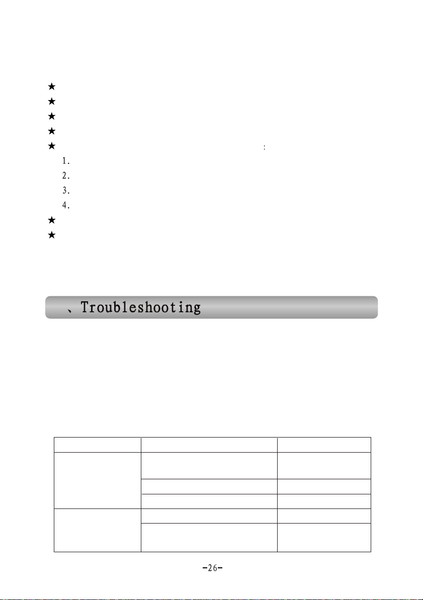
Before calling service, first check the following table for possible problems to
have slightly check or adjust. It might seem to solve the problems and make the unit
come back to order. If you are doubtful of this following table or solve the problems
ineffectively following these help, consult the professional service center.
Warning: It is very complicated. Do not open the CD changer or
Warning: It is very complicated. Do not open the CD changer or
try any repair.
try any repair.
ProblemProblem
LCD screen no
LCD screen no
any display
any display
No soundNo sound
Possible causePossible cause
The power switch and gniting
Switch are not switched on.
Connection wire is loose
Fuse is burnt out
The system is in UTE mode.
Connection wire of the
speaker is Loose.
SolutionSolution
Set the switches to ON.
Reconnecting
Replace with new fuse.
Leave the MUTE mode.
Reconnecting
Page 31
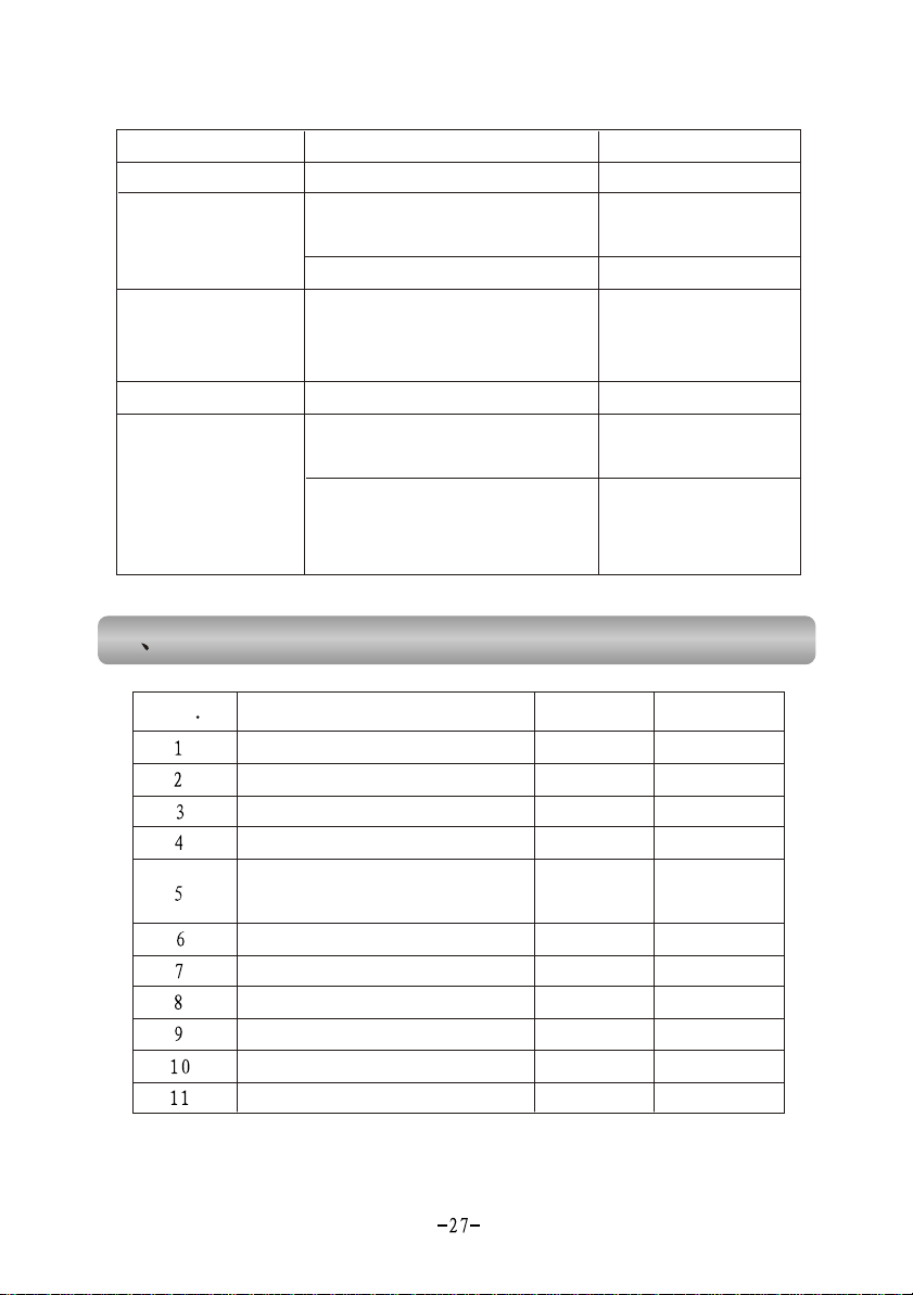
ProblemProblem
No soundNo sound
No imageNo image
Operation is
Operation is
failure.
failure.
Possible causePossible cause
The speakers is damaged.
The disc is not put in the
proper position.
The disc is dirty or damaged.
The functions are locked
SolutionSolution
Replace with new peakers
Put the side with label
upward on the tray.
Try other discs.
Pull out the power plug,
and insert after 10
seconds.
The sound skipsThe sound skips
The sound skips
The sound skips
from vibration
from vibration
Packing list Packing list
XV
NONO QTYQTY MemoMemo
Connecting wire from the
controller to disk
Battery of remote controller
Accessories of changer machine
Mainframe spare parts (screw, etc)
The disc is dirty or damaged.
The master control unit is
not properly mounted.
Mounting screw of the disc in
not fastened in right direction.
ItemsItems
DVD Host equipment
CD changer
Remote controller
Power audio output wire
Radar/Lens input wire
Manual
Try other discs.
Ensure the master control
unit is fixed firmly.
The screw adjust angle
marked V or H should
be adjust to the right
mounting direction.
1set
1set
1pc
1 strip
1 strip
1 strip
1pc
1set
1set
1pc
Options
Options
Options
Left & right
 Loading...