

Page 1

PLCD87
OWNER’S MANUAL
Mobile Audio System
• PLL Synthesizer Stereo Radio
• Digital Compact Disc Player
• Automatically Memory Storing
• Fold Down Detachable Panel
• Preset Equalization
• Auxiliary Input Function
• Remote Control
Page 2

CONTENTS
Installation .....................................................................................................3
DIN Front-Mount (Method A) ..................................................................................3
Installing the unit ...............................................................................................3
Removing the unit .............................................................................................4
DIN Rear-Mount (Method B)...................................................................................4
Using the Detachable Front Panel ..............................................................5
Wiring Connection ........................................................................................6
Operation .......................................................................................................7
General Operation ..................................................................................................8
Radio Operation......................................................................................................8
CD Operation..........................................................................................................9
Remote Control...........................................................................................10
Specification................................................................................................11
Trouble Shooting.........................................................................................12
2
Page 3

INSTALLATION
Notes:
• Choose the mounting location where
the unit will not interfere with the
normal driving function of the driver.
• Before finally installing the unit,
connect the wiring temporarily and
make sure it is all connected up
properly and the unit and the system
work properly.
• Use only the parts included with the
unit to ensure proper installation.
The use of unauthorized parts can
cause malfunctions.
• Consult with your nearest dealer if
installation requires the drilling of holes
or other modifications of the vehicle.
• Install the unit where it does not get in
the driver’s way and cannot injure the
passenger if there is a sudden stop,
like an emergency stop.
• If installation angle exceeds 30˚ from
horizontal, the unit might not give its
optimum performance.
DIN FRONT-MOUNT (Method A)
Installing the unit
1
182
53
(Fig. 1)
1. Dashboard
2. Holder
After inserting the holder into the
dashboard, select the appropriate tab
according to the thickness of the
dashboard material and bend them
inwards to secure the holder in place.
3. Screw
1
2
3
6
30˚
• Avoid installing the unit where it would
be subject to high temperature, such
as from direct sunlight, or from hot air,
from the heater, or where it would be
subject to dust, dirt or excessive
vibration.
DIN FRONT/REAR-MOUNT
This unit can be properly installed either
from “Front” (conventional DIN Frontmount) or “Rear” (DIN Rear-mount
installation, utilizing threaded screw holes
at the sides of the unit chassis).
For details, refer to the following
illustrated installation methods.
2
3
7
4
(Fig. 2)
5
1. Dashboard
2. Nut (5mm)
3. Spring washer
4. Screw (5 x 25mm)
5. Screw
6. Strap
Be sure to use the strap to secure the
back of the unit in place. The strap
can be bent by hand to the desired
angle.
7. Plain washer
3
Page 4

INSTALLATION
Removing the unit
1
Open
2
3
4
1. Before removing the frame, press the
OPEN button to slide down the front
panel.
2. Frame
3. Insert fingers into the groove in the
right side of the frame and pull out to
remove the frame. (You can also
remove the frame from the left side.)
4. Lever
After removing the frame, press the
OPEN button again to slide up the
front panel. Then insert the levers
supplied with the unit into the grooves
at both sides of the unit as shown in
figure until they click. Pulling the
levers makes it possible to remove the
unit from the dashboard.
DIN REAR-MOUNT (Method B)
Installation using the screw holes on the
sides of the unit.
1
2
4
2
3
Fastening the unit to the factory radio
mounting bracket.
1. Select a position where the screw
holes of the bracket and the screw
holes of the main unit become aligned
(are fitted), and tighten the screws at
2 places on each side.
Use either truss screws (5 x 5mm),
depending on the shape of the screw
holes in the bracket.
2. Screw
3. Factory radio mounting bracket
4. Dashboard or Console
Note: The mounting box, outer trim ring,
and half-sleeve are not used for method
B installation.
4
Page 5
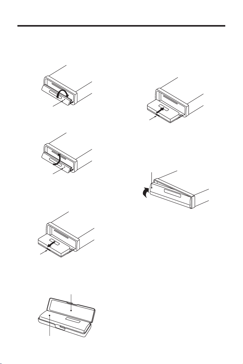
USING THE DETACHABLE FRONT PANEL
To Detach the Front Panel
1. Press the OPEN button, the front
panel will slide down.
Open
2. Press the OPEN button again, the
front panel will slide up.
Open
3. When the front panel slides down,
press the bottom button of the front
panel upward and pull it out from the
panel bracket.
To Reinstall the Front Panel
1. When the panel bracket is in slide
down position, insert the front panel
into panel bracket and press OPEN
button to slide up.
Bottom
Button
2. When the panel bracket is in slide up
position, insert a side of the front
panel to its proper position and push
the other side into the panel bracket,
a ‘click’ sound should be heard.
Front Panel
Bottom
Button
4. For safekeeping, store the front panel
in the supplied protective case
immediately after being removed.
Protective Case
Front Panel
3. Note that if the front panel fails to lock
in position properly, pressing control
button may not function and display
may be missing some segments.
Press the OPEN button and then
reinstall the front panel again.
5
Page 6
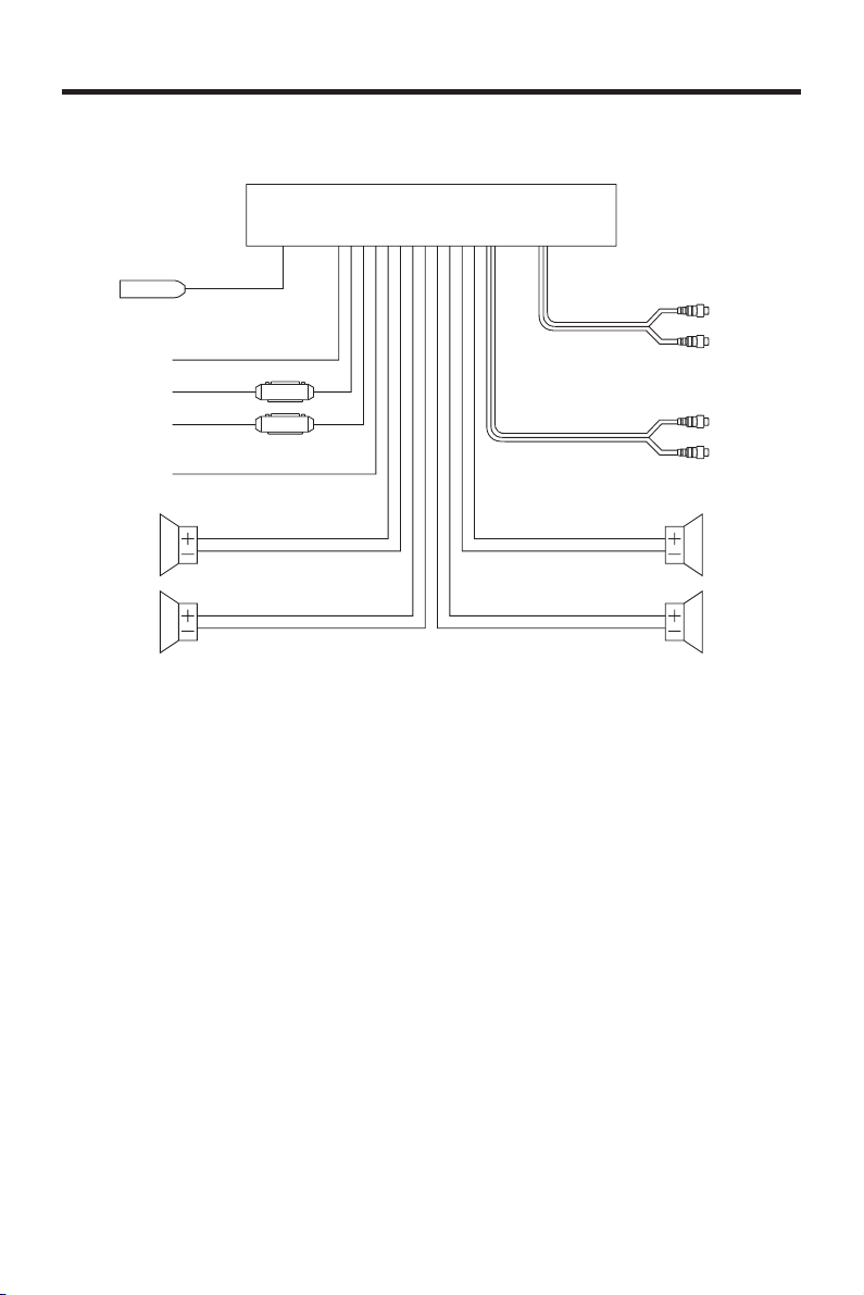
WIRING CONNECTION
ANTENNA CONNECTOR
POWER
RED
YELLOW
BLACK
BLUE
IGNITION
SWITCH (B+)
MEMORY
BACK-UP
GROUND (B–)
ANTENNA
MAIN UNIT
AUX IN
RCA CABLE
(BLACK)
(GREY)
Rch RED
Lch WHITE
Rch RED
Lch WHITE
FRONT Lch
SPEAKER
REAR Lch
SPEAKER
WHITE
WHITE/BLACK
GREEN
GREEN/BLACK
GREY
GREY/BLACK
VIOLET
VIOLET/BLACK
FRONT Rch
SPEAKER
REAR Rch
SPEAKER
6
Page 7
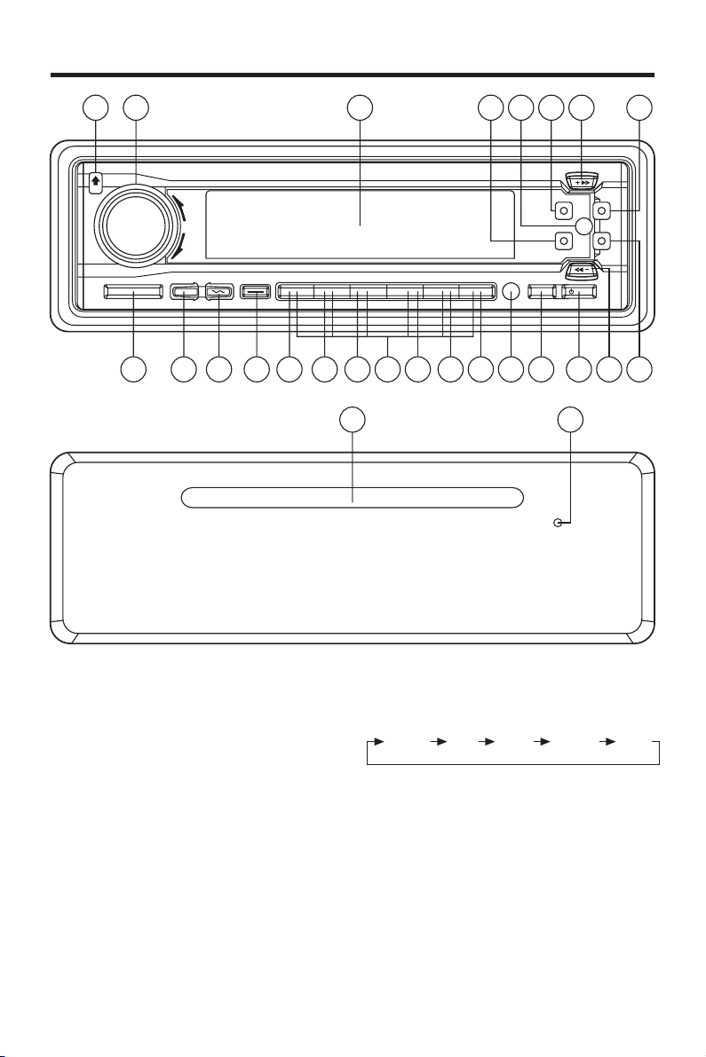
OPERATION
87
25
1415
22 23 24212019
5
121 2
13
16
1711106
26
39418
GENERAL OPERATION
• ON/OFF
Switch on the unit by pressing any
button [except OPEN button (7)].
When system is on, press PWR button
(9) to turn off the unit.
• FACEPLATE RELEASE
Press OPEN button (7) to detach the
removable faceplate.
• SOUND ADJUSTMENT
Press SEL button (10) shortly to select
the desired adjustment mode.
The adjustment mode will change in
the following order:
VOL BAS TRE BAL FAD
(Volume) (Bass) (Treble) (Balance) (Fader)
By rotating AUDIO ADJUST knob (8)
clockwise or counter-clockwise, it is
possible to adjust the desired sound
quality.
• LOUDNESS
Press BND/LOU button (13) for several
seconds to reinforce the bass output.
Press it for several seconds again to
release this function.
7
Page 8
OPERATION
• SET THE CLOCK
Press and hold DSP button (15), until
the clock is shown on the display and
flashes, then press the TUNE/TRACK
button (17) to change minutes or
TUNE/TRACK button (16) to
change hours.
• SELECT MODE
Press MODE button (6) shortly to
choose desired listening mode.
(e.g. radio mode to CD mode to
AUX IN mode)
The unit can be connected a portable
audio player through the AUX IN jack
(back of the unit).
• MUTE
Press MU button (3) to silence the
receiver. Press it again to release the
mode.
• LIQUID CRYSTAL DISPLAY
Exhibit current frequency and activated
functions on the display (25).
• EQUALIZATION
Press P-EQ button (11) to turn on
equalization function and to select
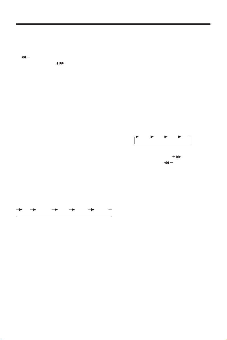
desired audio mode. There are five
kinds of mode as below:
FLAT CLASSICS POP M ROCK M DSP OFF
• REMOTE SENSOR
Point the remote control handset to
the remote sensor IR (12).
Press the function keys on the handset
to control the system.
• RESET
RESET button (26) must be activated
with either a ball point pen or thin metal
object. The RESET button is to be
activated for the following reasons:
- Initial installation of the unit when all
wiring is completed.
- All the function buttons do not
operate.
- Error symbol on the display.
Note: If press RESET button (26), the
unit can’t work yet, please use a cotton
swab soaked in isopropyl alcohol to
clean the socket on the back of the
front panel.
RADIO OPERATION
• BAND SELECTION
At tuner mode, press BND/LOU button
(13) to select the desired band.
The reception band will change in the
following order:
FM1 FM2 FM3 AM
• STATION SELECTION
Press TUNE/TRACK button (16)
or TUNE/TRACK
shortly to activate automatic seek
function. Press for several seconds
until “MANUAL” appeared on the
display, the manual tuning mode is
selected. If both buttons have not
pressed for several seconds, they will
return to seek tuning mode and
“AUTO” appeared on the display.
• LOCAL/DISTANCE
Press LO button (2) to select between
local and distant stations.
Local setting for reception of strong
station, and a distant setting for
reception of weaker stations.
This function is effect dring AUTO
SEEK operation.
• MONO/STEREO
Press MONO button (1) to select mono
or stereo mode. You can sometimes
improve reception of distant staions by
selecting mono operation.
8
button (17)
Page 9

OPERATION
• AUTOMATICALLY MEMORY
STORING & PROGRAM SCANNING
- Automatic Memory Storing
Press AMS button (18) for several
seconds, the radio searches from
the current frequency and checks
the signal strength until one cycle
search is finished. And then 6
strongest stations are stored into the
corresponding preset number
button.
- Program Scanning
Press AMS button (18) shortly to
scan preset station. When the field
strength level is more than the
threshold level of stop level, the radio
is holding at that preset number for
several seconds with releasing mute,
then searches again.
• STATION STORING
Press any one of the preset buttons
(14) (M1 to M6) to select a station
which had been stored in the memory.
Press this button for several seconds,
current station is stored into the
number button.
CD OPERATION
• SELECT TRACKS
During CD operation, press
TUNE/TRACK button (17) or
TUNE/TRACK (16) to move to the
previous track or the following track.
Track number shows on display.
During CD operation, hold
TUNE/TRACK button (17) or
TUNE/TRACK button (16) to fast
reverse or fast forward. CD play starts
from when you release the button.
• REPEAT THE SAME TRACK
During CD operation, press RPT
button (21) to continuously repeat the
same track. Press again to stop repeat.
• PREVIEW ALL TRACKS
During CD operation, press SCN
button (20) to play first several seconds
of each track on the current disc.
Press again to stop intro and listen to
track.
• PLAY ALL TRACKS IN RANDOM
During CD operation, press SHF
button (22) to play all tracks on CD in
random order. Press again to cancel
the function.
• COLOR BUTTON
Press the COL button (4) to adjust the
color of the LCD display. There are 7
kinds of color to be selected.
NOTE ON CD-R/CD-RW DISCS
• On this unit, in addition to an audio
CD, you can play your original CD-R
or CD-RW that contains audio titles.
• However, depending on the condition
of the recording equipment or the CDR or CD-RW itself, some CD-Rs or CDRWs cannot be played on this nite.
• DO NOT stick paper or tape, etc, onto
label side or the recording side of any
CD-R/CD-RW, as it may cause a
malfunction.
• PAUSE PLAYING
Press PAU button (19) to pause CD
player. Press it again to resume play.
9
Page 10
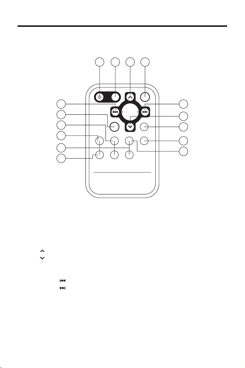
REMOTE CONTROL
REMOTE CONTROL HANDSET
1
8
6
13
4 3
7
9
5
2
12
10
11
14
15
FUNCTION KEYS & CONTROL
1. PWR = Power ON/OFF Button
2. DSP = Display Button
3. SEL = Select Button
4. VOL
5. VOL
6. BND = Band Select Button
7. MOD = Mode Button
8. TUNE/SEEK
9. TUNE/SEEK
10. AMS = Automatic Storing & Program Scanning Button
11. M1 - M6 = Preset Buttons
12. PAU = Pause Button
13. SCN = Scanning Button
14. RPT = Repeat Button
15. SHF = Shuffle Button
= Volume Up Button
= Volume Down Button
= Tune/Seek Down Button
= Tune/Seek Up Button
10
Page 11

SPECIFICATION
GENERAL
Power Supply Requirements : DC 12 Volts, Negative Ground
Chassis Dimensions : 178 (W) x 165 (D) x 50 (H)
Tone Controls
- Bass (at 100 Hz) : ± 10 dB
- Treble (at 10 KHz) : ± 10 dB
Maximum Output Power : 4 x 50 Watts
Current Drain : 15 Ampere (max.)
CD PLAYER
Signal to Noise Ratio : More than 60 dB
Channel Separation : More than 60 dB
Frequency Response : 20 Hz - 20 KHz
RADIO
Frequency Coverage : 87.5 to 107.9 MHz
IF : 10.7 MHz
Sensitivity (S/N = 30 dB) : 3 µV
Stereo Separation : > 30 dB
FM
Frequency Coverage : 530 to 1710 KHz
IF : 450 MHz
Sensitivity (S/N = 20 dB) : 32 dBu
AM
11
Page 12
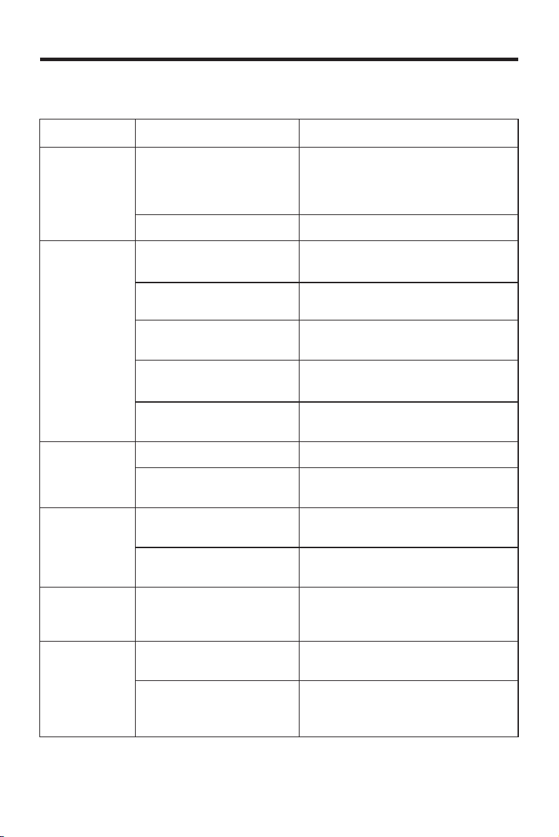
TROUBLE SHOOTING
Before going through the check list, check wiring connection. If any of the problems
persist after check list has been made, consult your nearest service dealer.
Symptom Cause Solution
No power. The car ignition switch is If the power supply is properly
Disc cannot Presence of CD disc inside Remove the disc in the player, then
be loaded or the player. put a new one.
ejected.
No sound. Volume is in minimum. Adjust volume to a desired level.
Sound skips. The installation angle is Adjust the installation angle to less
not on. connected to the car accessory
circuits, but the engine is not moving,
switch the ignition key to “ACC”.
The fuse is blown. Replace the fuse.
Inserting the disc in Insert the compact disc with the
reverse direction. label facing upward.
Compact disc is extremely Clean the disc or try to play a new
dirty or defective disc. one.
Temperature inside the car Cool off or until the ambient
is too high. temperature return to normal.
Condensation. Leave the player off for an hour or
so, then try again.
Wiring is not properly Check wiring connection.
connected.
more than 30 degrees. than 30 degrees.
The disc is extremely dirty Clean the compact disc, then try to
or defective disc. play a new one.
The operation The built-in microcomputer Press the RESET button.
keys do not is not operating properly Front panel is not properly fixed into
work. due to noise. its place.
The radio does The antenna cable is not Insert the antenna cable firmly.
not work. The connected.
radio station
automatic The signals are too weak. Select a station manually.
selection does
not work.
www.pyleaudio.com
12
88-C1560-69
 Loading...