

Page 1

www.pyleaudio.com
damage.
improperly serviced, or subject to misuse, neglect, or accidental
This warranty will be considered void if the unit was tampered with,
replacement of the defective unit when it is returned to us prepaid.
Our obligation under this warranty is limited to the repair or
expiration date.
handling, and insurance, or provide your Visa/MC number with
• also include a check or money order for $12.00 for return shipping,
and R.A. number
• include in your letter your return address, daytime phone number,
• A brief letter indicating the problem you are experiencing
• A copy of your sales receipt or other proof of purchase
You must also include the following items:
Brooklyn, NY 11204
1600 63rd Street
Pyle Service Center
R.A.#
and shipped prepaid to:
When returning a product to us for warranty service it must be carefully packed
relating to your return.
R.A.# must appear on the outside of your package and on all paperwork
number at (718) 236-6948 to obtain a Return Authorization number. This
To obtain warranty service you must first call our Consumer Return Hotline
your unit will be repaired or replaced at the sole discretion of Pyle.
Should the product fail due to factory defects in material or workmanship,
warranty is limited to the original retail purchase.
in material and workmanship for two (2) years from the date of purchase. This
shipment. Products purchased in the USA are warranted to be free of defects
All Pyle products are carefully constructed and thoroughly tested before
wave
amplifiers
blue
limited warranty policy
user’s manual
blue
wave
high performance car audio amplifier
PLA585R
PLA985R
PLA1485R
Page 2

congratulations...
blue
on your purchase of a Pyle Blue Wave Series amplifier. This amplifier
extends the Pyle tradition into a totally new series of amps, designed
from the ground up to deliver the power, performance and flexibility
the modern car audio enthusiast demands.
When you check the list of features offered by the PLA585R, PLA985R
, and PLA1485R, you’ll know you made the right choice with a Pyle
Blue Wave amplifier.
wave
table of contents
blue
general features
features and specifications
PLA585R
PLA985R
PLA1485R
electrical connections
PLA585R/985R
PLA1485R
stereo input connections
PLA585R/985R
mono input connections
PLA585R/985R
2/4 channel input connections
PLA1485R
high level input connections
PLA1485R
wave
2-3
4-5
6-7
8-9
10
11
12
13
14
15
high level mono input connections
PLA585R/985R
protection circuitry and troubleshooting
mono input connections
PLA1485R
PLA1485R
speaker connections
speaker connections
PLA1485R
mounting and installation
precautions
16
17
18
19-20
21
22
23
Page 3

general features
blue
PLA585R
High Performance 700 Watt 2 Channel
Bridgeable MOSFET Amplifier
· 350 Watts x 2 Output
· 700 Watts x 1 Bridged Output
· Variable Hi/Lo Electronic Crossover Network
· Variable Bass Boost (0 - +18 dB @ 60Hz)
· Variable Input Level (Gain) Control
· Remote Turn On/Off
· Gold Plated RCA Inputs
· High Level MOLEX Input
· Power ON LED Indicator
· LED Protection Indicator
.Remote Bass Boost
· S/N Ratio: > 95 dB
· THD: <0.04%
· Thermal Protection
· Overload Protection
· Short Circuit Protection
· Anti-Thump Turn-On
wave
PLA985R
High Performance 1000 Watt 2 Channel
Bridgeable MOSFET Amplifier
· 500 Watts x 2 Output
· 1000 Watts x 1 Bridged Output
· Variable Hi/Lo Electronic Crossover Network
· Variable Bass Boost (0 - +18 dB @ 60Hz)
· Variable Input Level (Gain) Control
· Remote Turn On/Off
· Gold Plated RCA Inputs
· High Level MOLEX Input
· Power ON LED Indicator
· LED Protection Indicator
.Remote Bass Boost
· S/N Ratio: > 95 dB
· THD: <0.04%
· Thermal Protection
· Overload Protection
· Short Circuit Protection
· Anti-Thump Turn-On
2
blue
PLA1485R
High Performance 1600 Watt 4 Channel
Bridgeable MOSFET Amplifier
· 400 Watts x 4 Output
· 800W x 2 Bridged Output (400W x 2 + 800W x 1)
· Dual Variable Hi/Lo Electronic Crossover Network
· Dual Variable Bass Boost (0 - +18 dB @ 60Hz)
· Variable Input Level (Gain) Control
· Remote Turn On/Off
· Gold Plated RCA Inputs
· High Level MOLEX Inputs
· Power ON LED Indicator
· LED Protection Indicator
.Remote Bass Boost
· S/N Ratio: > 95 dB
· THD: <0.04%
· Thermal Protection
· Overload Protection
· Short Circuit Protection
· Anti-Thump Turn-On
· Tri-Mode Configurable
general features
wave
3
Page 4
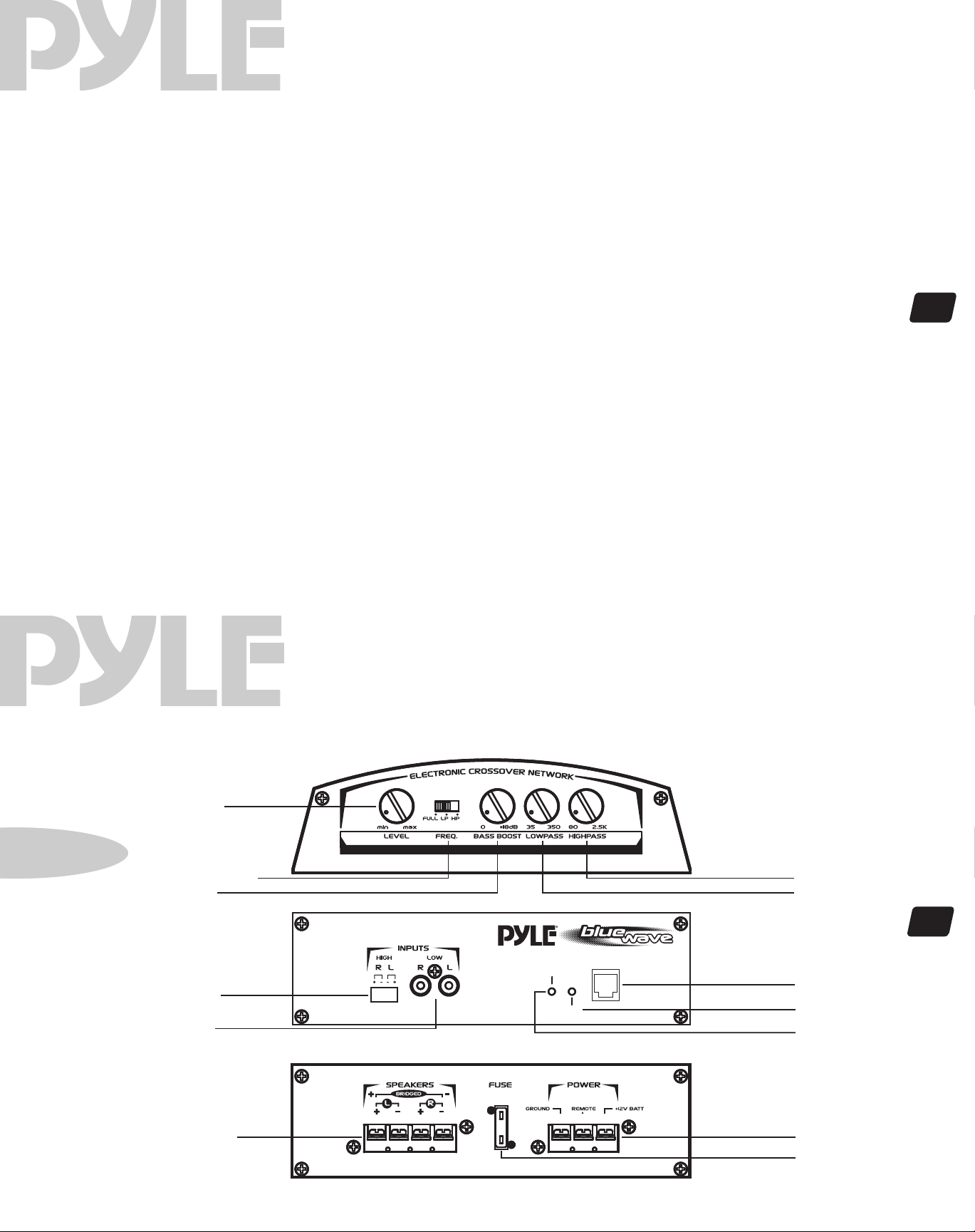
features and specifications
blue
crossover mode selector
input level control
low pass frequency control
high pass frequency control
bass boost level control
low level inputs
high level inputs
power LED
protection LED
Remote Bass Boost
power fuse
power terminals
speaker connections
2 ch amp PLA585R
when used with normal, full range systems, set this switch to “FULL.” If
you wish to use the internal crossover to power a driver of specific frequency
range, use the “LOWPASS” or “HIGHPASS” settings.
use this control to match the outputs of your head unit to the amplifier.
Starting with your head unit set at about the 2 o’clock position, increase
the amp level control until distortion begins to occur, and reduce slightly
from this point.
when the crossover selector switch is in “low pass” mode, this control
sets the upper frequency limit for audio program sent to the speakers.
when the crossover selector switch is in “high pass” mode, this control
sets the lower frequency limit for audio program sent to the speakers.
this control permits adjustment of the bass level up to an increase of
approximately 18 dB.
this amp features gold-plated RCA input jacks for high impedance input.
Use these with car stereo output which uses RCA-type connector cables.
if your car stereo lacks RCA-type output jacks, you may connect speaker
output leads to these input connectors.
this indicator is illuminated when power is applied.
this indicator is illuminated when built-in protection circuitry is activated.
Plug in the Remote Bass Boost Control wire in here.
the fuse protects the amplifier and your car’s electrical system from short
circuit conditions.
use these connectors to deliver power, ground and remote turn-on control
to the amplifier.
these terminals are 14K gold plated to guarantee high conductivity and
minimum signal loss.
PLA585R
wave
output power @ 14.4v DC, 1KHz
RMS Power @ 4 Ohms
RMS Power @ 2 Ohms
Maximum Power Output
frequency response
input impedance
low level inputs
high level inputs
input sensitivity
low level inputs
high level inputs
power supply voltage
matching speaker impedance
stereo mode
bridged mode
maximum current draw
dimensions (W x H x L)
mm
inches
2 channel amplifier
55 Watts x 2
85 Watts x 2
350 Watts x 2
15 Hz-30 KHz
10K Ohms
100 Ohms
250mV
2.5V
14.4V DC Neg. Ground (10.5-16V)
2-4 Ohms
4-8 Ohms
15A
300 x 62 x 245
11.8 x 2.4 x 9.7
4
pla585R
features and controls
blue
input level control
crossover mode selector
bass boost level
high level inputs
low level inputs
2 ch amp PLA585R
wave
REMOTE
POWER
PROTECTION
BASS BOOST
high pass frequency control
low pass frequency control
5
Remote Bass Bost
protection LED
power LED
speaker connections
power terminals
power fuse
Page 5
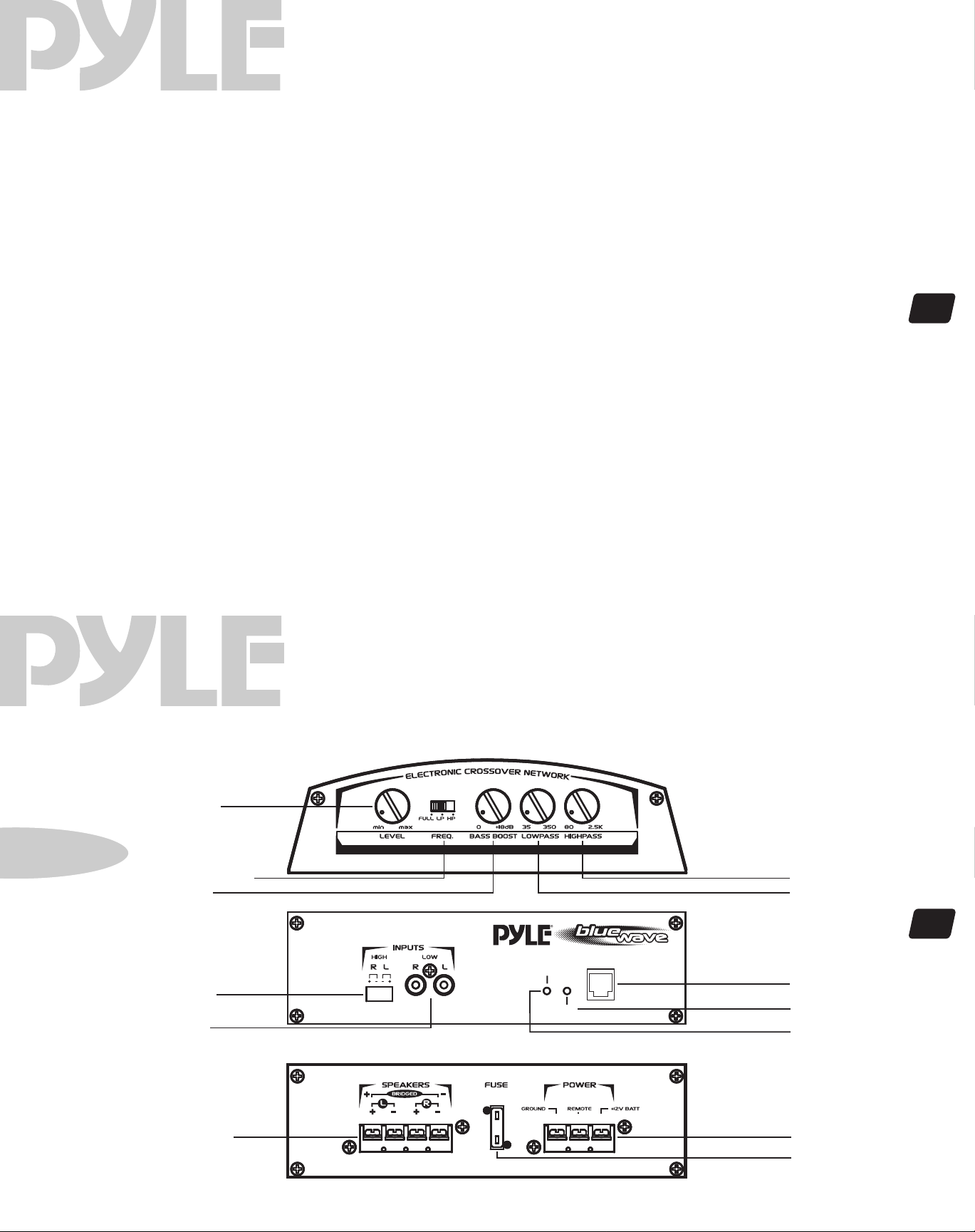
features and specifications
blue
crossover mode selector
input level control
low pass frequency control
high pass frequency control
bass boost level control
low level inputs
high level inputs
power LED
protection LED
Remote Bass Boost
power fuse
power terminals
speaker connections
2 ch amp PLA985R
when used with normal, full range systems, set this switch to “FULL.” If
you wish to use the internal crossover to power a driver of specific frequency
range, use the “LOWPASS” or “HIGHPASS” settings.
use this control to match the outputs of your head unit to the amplifier.
Starting with your head unit set at about the 2 o’clock position, increase
the amp level control until distortion begins to occur, and reduce slightly
from this point.
when the crossover selector switch is in “low pass” mode, this control
sets the upper frequency limit for audio program sent to the speakers.
when the crossover selector switch is in “high pass” mode, this control
sets the lower frequency limit for audio program sent to the speakers.
this control permits adjustment of the bass level up to an increase of
approximately 18 dB.
this amp features gold-plated RCA input jacks for high impedance input.
Use these with car stereo output which uses RCA-type connector cables.
if your car stereo lacks RCA-type output jacks, you may connect speaker
output leads to these input connectors.
this indicator is illuminated when power is applied.
this indicator is illuminated when built-in protection circuitry is activated.
Plug in the Remote Bass Boost Control wire in here.
the fuse protects the amplifier and your car’s electrical system from short
circuit conditions.
use these connectors to deliver power, ground and remote turn-on control
to the amplifier.
these terminals are 14K gold plated to guarantee high conductivity and
minimum signal loss.
PLA985R
wave
output power @ 14.4v DC, 1KHz
RMS Power @ 4 Ohms
RMS Power @ 2 Ohms
Maximum Power Output
frequency response
input impedance
low level inputs
high level inputs
input sensitivity
low level inputs
high level inputs
power supply voltage
matching speaker impedance
stereo mode
bridged mode
maximum current draw
dimensions (W x H x L)
mm
inches
2 channel amplifier
90 Watts x 2
130 Watts x 2
500 Watts x 2
15 Hz-30 KHz
10K Ohms
100 Ohms
250mV
2.5V
14.4V DC Neg. Ground (10.5-16V)
2-4 Ohms
4-8 Ohms
20A
300 x 62 x 305
11.8 x 2.4 x 12
6
pla985R
features and controls
blue
input level control
crossover mode selector
bass boost level
high level inputs
low level inputs
2 ch amp PLA985R
wave
REMOTE
POWER
PROTECTION
BASS BOOST
high pass frequency control
low pass frequency control
7
Remote Bass Bost
protection LED
power LED
speaker connections
power terminals
power fuse
Page 6
blue
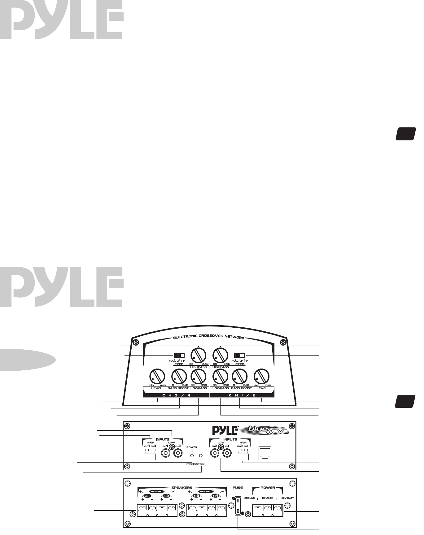
dual crossover mode selectors
dual input level controls
dual low pass frequency controls
dual high pass frequency controls
dual bass boost level controls
low level inputs
high level inputs
power LED
protection LED
Remote Bass Boost
power fuse
power terminals
speaker connections
features and specifications
4 ch amps PLA1485R
when used with normal, full range systems, set these switches to “FULL.”
If you wish to use the internal crossovers to power a driver of specific
frequency range, use the “LOWPASS” or “HIGHPASS” settings.
use these controls to match the outputs of your head unit to the amplifier.
Starting with your head unit set at about the 2 o’clock position, increase
the amp level controls until distortion begins to occur, and reduce slightly
from this point.
when one or both of the crossover selector switches is in “low pass”
mode, one can set the upper frequency limit for audio program sent to
the speakers.
when the one or both of crossover selector switch is in “high pass” mode,
one can set the lower frequency limit for audio program sent to the
speakers.
this control permits adjustment of the bass level up to an increase of
approximately 18 dB in either or both pairs of channels.
this amp features gold-plated RCA input jacks for high impedance input.
Use these with car stereo output which uses RCA-type connector cables.
if your car stereo lacks RCA-type output jacks, you may connect speaker
output leads to these input connectors.
this indicator is illuminated when power is applied.
this indicator is illuminated when built-in protection circuitry is activated.
Plug in the Remote Bass Boost Control wire in here.
the fuse protects the amplifier and your car’s electrical system from short
circuit conditions.
use these connectors to deliver power, ground and remote turn-on control
to the amplifier.
these terminals are 14K gold plated to guarantee high conductivity and
minimum signal loss.
wave
output power @ 14.4v DC, 1KHz
RMS Power @ 4 Ohms
RMS Power @ 2 Ohms
Maximum Power Output
frequency response
input impedance
low level inputs
high level inputs
input sensitivity
low level inputs
high level inputs
power supply voltage
matching speaker impedance
stereo mode
bridged mode
maximum current draw
dimensions (W x H x L)
mm
inches
14.4V DC Neg. Ground (10.5-16V)
PLA1485R
4 channel amplifier
105 Watts x 4
155 Watts x 4
400 Watts x 4
15 Hz-30 KHz
10K Ohms
100 Ohms
250mV
2.5V
2-4 Ohms
4-8 Ohms
40 A
300 x 62 x 425
11.8 x 2.4 x 16.7
8
pla1485R
features and controls
blue
ch 3/4 high pass frequency control
ch 3/4 crossover mode selector switch
ch 3/4 input level control
ch 3/4 bass boost level control
ch 3/4 low pass frequency control
ch 3/4 low level inputs
ch 3/4 high level inputs
power LED
protection LED
4 ch amps PLA1485R
wave
REMOTE
BASS BOOST
ch 1/2 high pass frequency control
ch 1/2 crossover mode selector switch
ch 1/2 input level control
ch 1/2 bass boost level control
ch 1/2 low pass frequency control
Remote Bass Bost
ch 1/2 high level inputs
ch 1/2 low level inputs
9
speaker connections
power terminals
fuse
Page 7
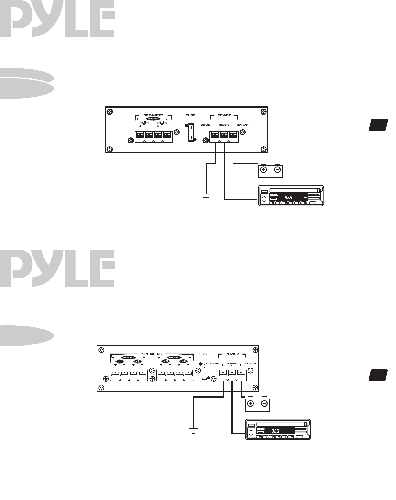
pla585R
pla985R
electrical connections
blue
2 ch amps PLA585R•PLA985R
wave
10
12V battery
head unit
pla1485R
electrical connections
blue
to remote turn-on
+12V
4 ch amps PLA1485R
wave
to remote turn-on
+12V
11
12V battery
head unit
Page 8
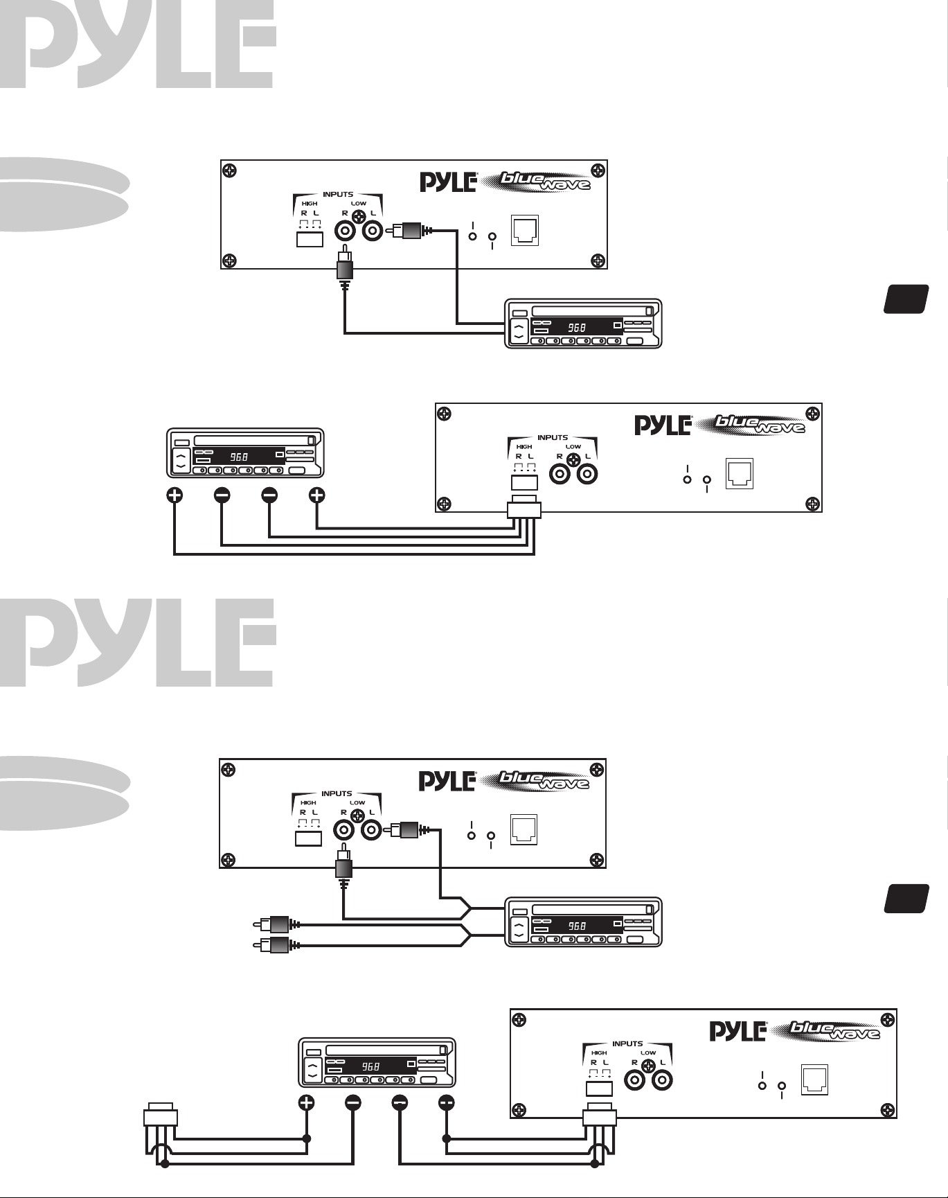
pla585R
pla985R
stereo input connections
blue
using low level inputs
2 ch amps PLA585R•PLA985R
wave
REMOTE
POWER
PROTECTION
BASS BOOST
L/R Audio
Outputs
head unit
L L RR
from spealer terminals
mono input connections
blue
head unit
PLEASE NOTE! If using high
level inputs, do not use the
using high level inputs
POWER
PROTECTION
wiring harness
low level RCA inputs at the
same time!
REMOTE
BASS BOOST
2 ch amps PLA585R•PLA985R
wave
12
pla585R
pla985R
using low level inputs
To a second amplifier
To a second amplifier
Y Adaptors
head unit
RRLL
POWER
PROTECTION
REMOTE
BASS BOOST
head unit
using high level inputs
wiring harnesswiring harness
13
PLEASE NOTE! If using high
level inputs, do not use the
low level RCA inputs at the
same time!
REMOTE
POWER
PROTECTION
BASS BOOST
from spealer terminals
Page 9
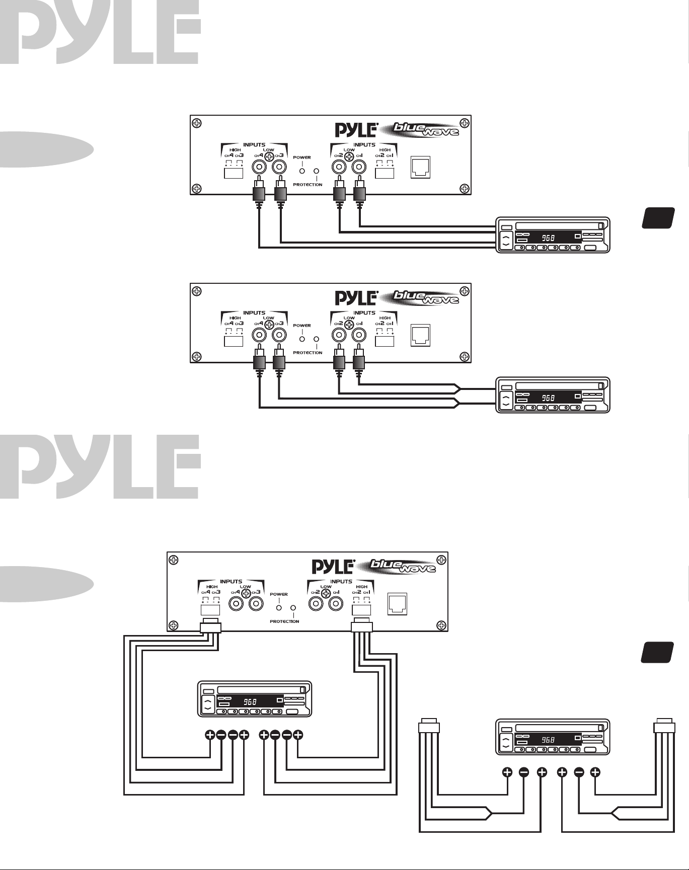
pla1485R
2/4 channel input connections
blue
4 CH input connections using low level inputs
4 ch amps PLA1485R
wave
REMOTE
BASS BOOST
L/R REAR
Audio Outputs
2 CH input connections using low level inputs
high level input connections
blue
L/R FRONT
Audio Outputs
REMOTE
BASS BOOST
Y adaptors
4 ch amps PLA1485R
wave
head unit
14
L
R
pla1485R
PLEASE NOTE! If using high level
inputs, do not use the low level
RCA inputs at the same time!
4 CH floating ground connections
L R FRONTRLREAR
ORANGE
BLACK
BLACK
ORANGE
from speaker terminals
ORANGE
BLACK
BLACK
ORANGE
REMOTE
BASS BOOST
4 CH harness wiring for common ground connections
CH 3/4
L R FRONTRLREAR
ORANGE
BLACK
BLACK
ORANGE
from speaker terminals
ORANGE
BLACK
BLACK
ORANGE
15
CH 1/2
Page 10
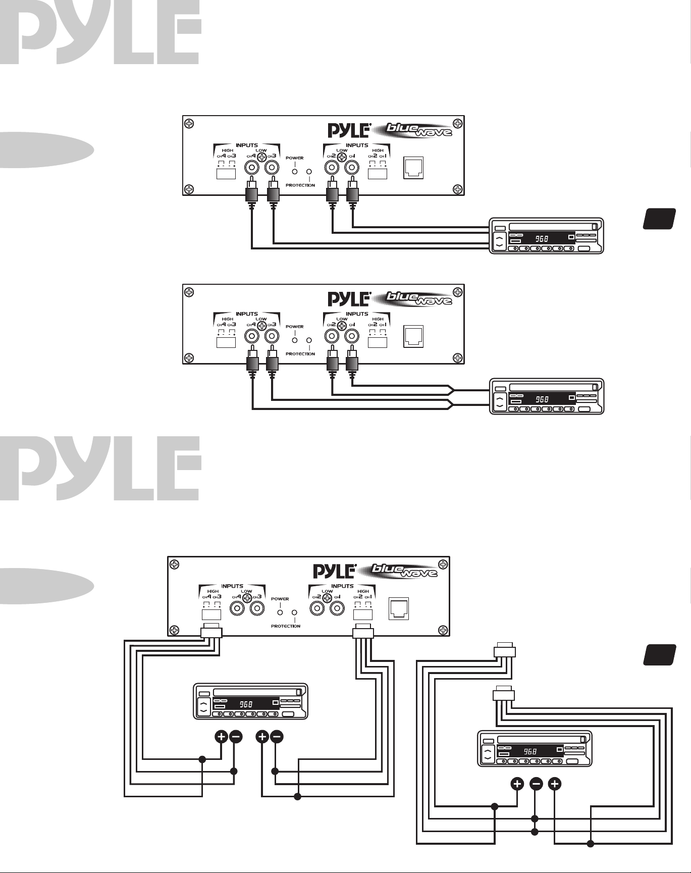
pla1485R
mono input connections
4 ch amps PLA1485R
blue
4 CH mono input connections using low level inputs
RIGHT FRONT Audio Outputs
RIGHT REAR Audio Outputs
2 CH mono input connections using low level inputs
wave
REMOTE
BASS BOOST
head unit
LEFT FRONT Audio Outputs
LEFT REAR Audio Outputs
REMOTE
BASS BOOST
16
pla1485R
high level mono input connections
blue
4 CH floating ground connections
L
Y adaptors
R
4 ch amps PLA1485R
wave
REMOTE
BASS BOOST
CH 3/4
17
ORANGE
BLACK
BLACK
ORANGE
PLEASE NOTE! If using high level
inputs, do not use the low level
RCA inputs at the same time!
R L
from speaker terminals
for common ground connections
ORANGE
BLACK
BLACK
ORANGE
4 CH harness wiring
ORANGE
BLACK
BLACK
ORANGE
CH 1/2
R L
ORANGE
BLACK
BLACK
ORANGE
from speaker terminals
Page 11
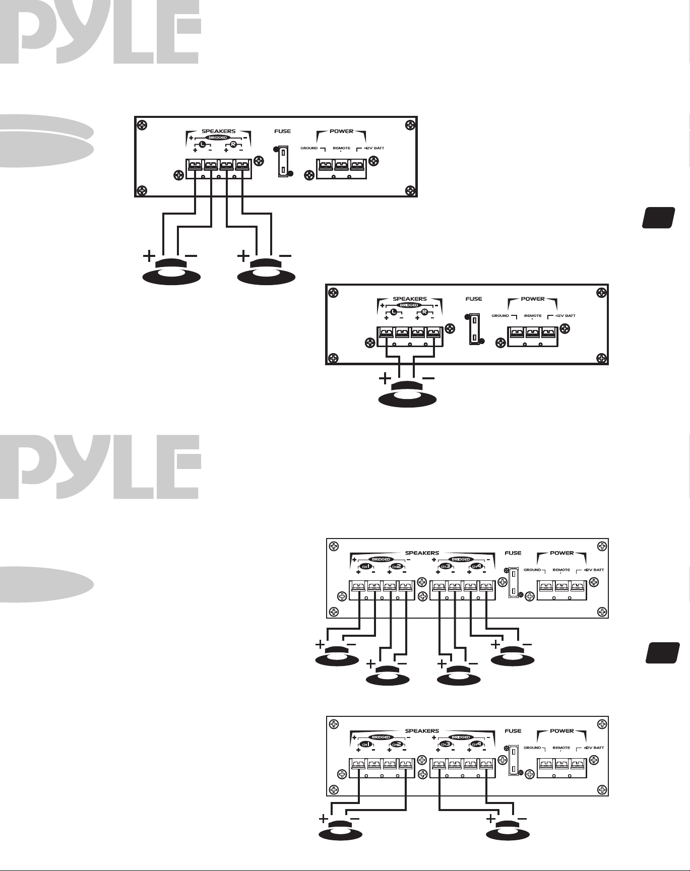
pla585R
pla985R
speaker connections
blue
Stereo Output Mode
LEFT speaker RIGHT speaker
2 ch amps PLA585R•PLA985R
wave
18
Bridged Mono Output Mode
pla1485R
speaker connections
blue
4 CH Output Mode
MINIMUM
SPEAKER
IMPEDANCE
speaker
4 ch amps PLA1485R
4 OHMS!
wave
19
Bridged Dual Mono Output Mode
L R
FRONT speakers
L R
R L
speakers
REAR speakers
MINIMUM
SPEAKER
IMPEDANCE
4 OHMS!
Page 12
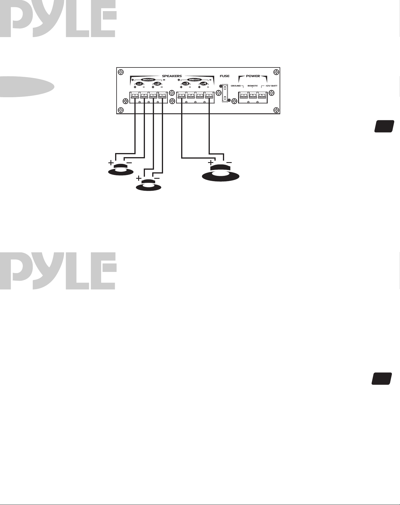
pla1485R
speaker connections
4 ch amp PLA1485R
blue
2 CH Stereo Output Mode with Mono Bridged Subwoofer Output
wave
mounting
Your new Pyle Blue Wave Series amplifier comes complete with all required mounting hardware. When determining a suitable location in your vehicle for the amp, please remember
that it is a high-power electronic device capable of generating high heat.
blue
L
SPEAKERS
MINIMUM
SPEAKER
IMPEDANCE
4 OHMS!
R
SUBWOOFER
mounting and installation
PLA585R•PLA985R•PLA1485R
wave
20
For this reason, always choose a location in your vehicle which has low vibration, adequate ventilation, a minimum of dust, and no moisture. Be sure to mount
the amp in such a manner as to allow reasonable airflow over the cooling fins.
Mark the location for the mounting screw holes by positioning the amp where you wish to install it and use a scribe (or one of the mounting screws) inserted in each of
the mounting holes to mark the mounting surface. If the mounting surface is carpeted, measure the hole centers and mark with a felt tip pen.
Before attempting to drill the mounting holes, take note of any wires, lines or other devices in your vehicle which may be located behind the mounting
surface! Then drill pilot holes in the mounting surface for the mounting screws and insert them. Tighten the screws securely.
wiring tips
fuses
When making electrical connections to your amplifier, please observe the
following:
Use at least 8 gauge wire for power and ground connections.
Wire the amplifier directly to the car battery.
For the ground connection, use the shortest possible wire to a good chassis ground point.
Wire the Remote connection to the auto start lead of your head unit, equalizer or power antenna.
About power fuses:
Pyle Blue Wave Series amplifiers feature built-in fuse systems. These fuses protect both the
amplifier and the electrical system in your vehicle from fault conditions. If you ever need to
replace the fuse in your Pyle Blue Wave Series amp, use a fuse of exactly the same type and
rating. A different type or rating of fuse may result in damage or fire.
21
Page 13

protection
circuitry
The built-in protection circuitry in the Pyle Blue
Wave amplifiers will disable the amplifier if it senses
an input overload, a speaker short circuit, or extreme
temperature conditions.
blue
troubleshooting
No output.
Confirm that all terminal strip connections are secure and tight.
Check both in-line and built-in fuses. Both the +12V and the Remote terminals must have +12v referenced to chassis
ground.
wave
When the protection circuit is activated by any of
these conditions, the Protection LED will be
illuminated.
If this occurs, carefully inspect the system to
determine the source of the problem.
• If the shutdown was a result of a thermal overload
condition, allow the amplifier to cool down before
attempting to restart it.
• If the shutdown was a result of an input overload,
or speaker short circuit, be sure to correct the
condition before restarting.
The amplifier can be restarted by turning the remote
power OFF and then ON again.
Confirm that the audio signal source (car radio, equalizer, etc.) is connected and is supplying output signal. To
check if the amp is supplying signal, unplug the cables from the signal source (but leave them plugged into the
amp). Briefly tap the center pin of each of the disconnected RCA plugs with your finger . This should produce a noise
(feedback) in your speakers.
Only one channel works.
Confirm that all terminal strip connections are secure and tight.
Check the Balance control on the head unit (or other source) to verify that it is set to its midpoint.
If you are using the Low Level RCA input, reverse the input plugs at the amplifier (i.e., switch the L with the R). If
the channels which is silent switches to the other side, the problem is either in the head unit/other source or the
connecting cables.
Weak output.
Readjust the Input Level Control(s) to better suit the input signal.
Noise in the audio.
If the noise is a “whine” whose pitch follows the engine speed, confirm that the amplifier and any other signal
sources (head unit, etc.) are properly grounded.
If the noise is a “clicking” or “popping” noise whose rate follows the engine speed, this usually means that the
vehicle is equipped with resistor spark plugs and wires, or that the ignition is in need of service.
Check the rounting of the speaker and input wires to make sure they are not adjacent to wires which interconnect
lights and other accessories.
If the above steps fail to improve or clear noise interference, the system should be checked by a professional mobile
audio installer.
22
precautions notes
Do not operate the amplifier when it is unmounted.
Attach all audio system components securely within
the automobile to prevent damage, especially in an
accident.
Do not mount this amplifier so that the wire
connections are unprotected, or in a pinched
condition, or likely to be damaged by nearby objects.
Before making or breaking power connections in
your system, disconnect the vehicle battery. Confirm
that your head unit or other equipment is turned off
while connecting the input jacks and speaker
terminals.
If you need to replace the power fuse, do so only
with a fuse identical to that supplied with the amplifier .
Using a fuse of a different type or rating may result
in damage that isn’t covered in the manufacturer’s
warranty.
blue
wave
23
 Loading...