

Page 1

R
PDWM5500
WIRELESS MICROPHONE SYSTEM
POWER
OPERATING INSTRUCTIONS
PWM A5 00 0 P ROF ES SI ON AL W IR EL ES S M ICR OP HO NE SY STE M
Page 2

.........SPECIFICATION.........
...........PREFACE...........
System Specific ations
1) Carrier Frequency:.................... VHF 160-280MHz
2) Frequency Stability:.....................0.005%
3) Modulation mode:.....................VHF
4) Audio Frequency Response:................60Hz-16KHz
5) Signal to Noise Ratio:...................>60dB
6) Maximum Sound Pressure Level:..............>100dB
7) Distortion:........................<0.5%
8) Operating Range:.....................Approx 240 ft.
Transm itt er
1) RF Output Power: .....100mW MAX
2) Harmonic Suppression:...................40dB
3) Antenna:.........................Builtin
4) Power Supply:.......................1.5V(AA) x3
5) Nominal Current Drain:...................Approx. 15mA
6) Battery Life:........................Approx. 12 hours
................
Receiver
1) Receive Mode:......................Crystal Frequency Lock
2) Sensitiity:.........................40dBu(S/N=60dB)
3) SignaltoNoise Ratio:....................>60dB
4) Audio Output Level:....................400mV Max
5) Power Supply:.......................AC110V/220V(.10%) DC12v-18v/500mA
Thank you for selecting the PDWM5500 4 Mic VHF Wireless System. Before operating please read this instruction manual carefully
and thoroughly in order to understand the correct operating procedures and achieve the best results.
FEATU RES:
ALC circuit to eliminate distortion:
Frequency compressing/expanding (companding) circuitry to lower noise and increase the dynamic range.
Superior squelch and high signal to noise ration.
Near zero noise output when on standby.
Wide frequency response range and low distortion.
Convenient operation status indicators.
LED Displays.
Multiple HF and MF narrowband filters to eliminate interfering signal.
Low power consumption components to ensure longer battery life.
Special impact wave eliminating circuit for microphone switch.
Long transmitting distance-up to 240 ft. in ideal circumstances.
SYSTEM SETUP
1) Plug the included audio cable into the receiver's mixed output connector, and the other end into a mixer or power amplifier system.
Extend the two antennas fully to the vertical position. Switch on the receiver. The POWER ON light will illuminate.
2) Open the battery cover of the microphone and install the batteries inside the compartment properly. Replace the cover.
3) Position the transmitter power switch to ON. The indicator light will illuminate. The microphone features a 3-way power switch. The
middle position (standby) functions as a mute switch.
4) The receiver's corresponding channel light will illuminate, indicating reception.
5) Adjust the volume knobs of the receiver and power amplifier.
6) When the transmitter power indicator dims, it indicates low battery power. Replace the batteries.
- 4 -
- 1 -
Page 3
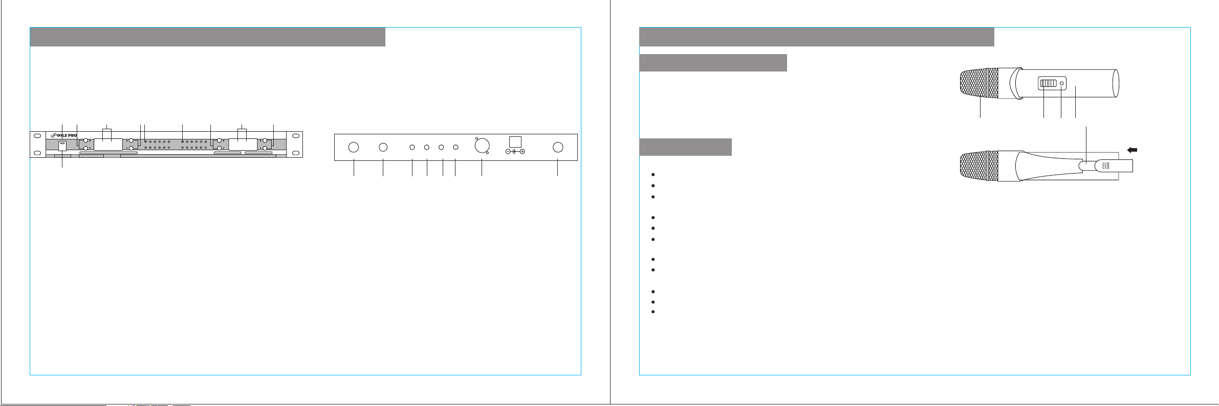
.....RECEIVER AND TRANSMITTER.....
.....RECEIVER AND TRANSMITTER.....
Description
1 3 4 5 6 7 8 9 10
PWMA 50 00 PR OF ESS IO NA L W IRE LE SS MI CR OPH ON E S YS TE M
POWER
2
1) Power Indicator
2) Power Switch
3) CH.A Volume Control
4) CH.A/B LED Displays
5) CH.B Volume Control
6) CH.A/B AF Meters
7) CH.C/D AF Meters
8) CH.C Volume Control
REAR PANEL OF RECEIVERFRONT PANEL OF RECEIVER
ANT.CD MIX OUT ANT.ABOUT.D OUT.C OUT.B OUT.A BALANCED DC13V/500mA
11 12 14
9) CH.C/D LED Displays
10)CH.D Volume Control
11) CH. C/D Antenna Connector
12) Individual Audio Output
13) Mixed Audio Output
14)CH.A/B Antenna Connector
15)AC Power Input (voltage selectable)
- 2 -
1) Grill
2) Power Switch
3) LED Power Indicator
4) Mic Body
5) Battery Compartment
Troublesh ooting
1. Unit does not turn on.
Make sure the power cable is connected properly.
Check the fuse.
Check the voltage selector
2. AF display moves, but there is no sound output.
Check volume level.
Check audio cable.
Check the settings on your amplifier.
3. The effective receiving distance decreases.
Change batteries.
Check for any devices that may be causing interference.
4. Sound Quality Deteriorates
Change Batteries.
Check for any devices that may be causing interference.
Do not use two machines with the same frequency at the same time.
Caution:
Do not open the unit. There are no user serviceable parts
inside. Refer service to a qualified technician.
- 3 -
1 2 3 4 5
 Loading...