

Page 1
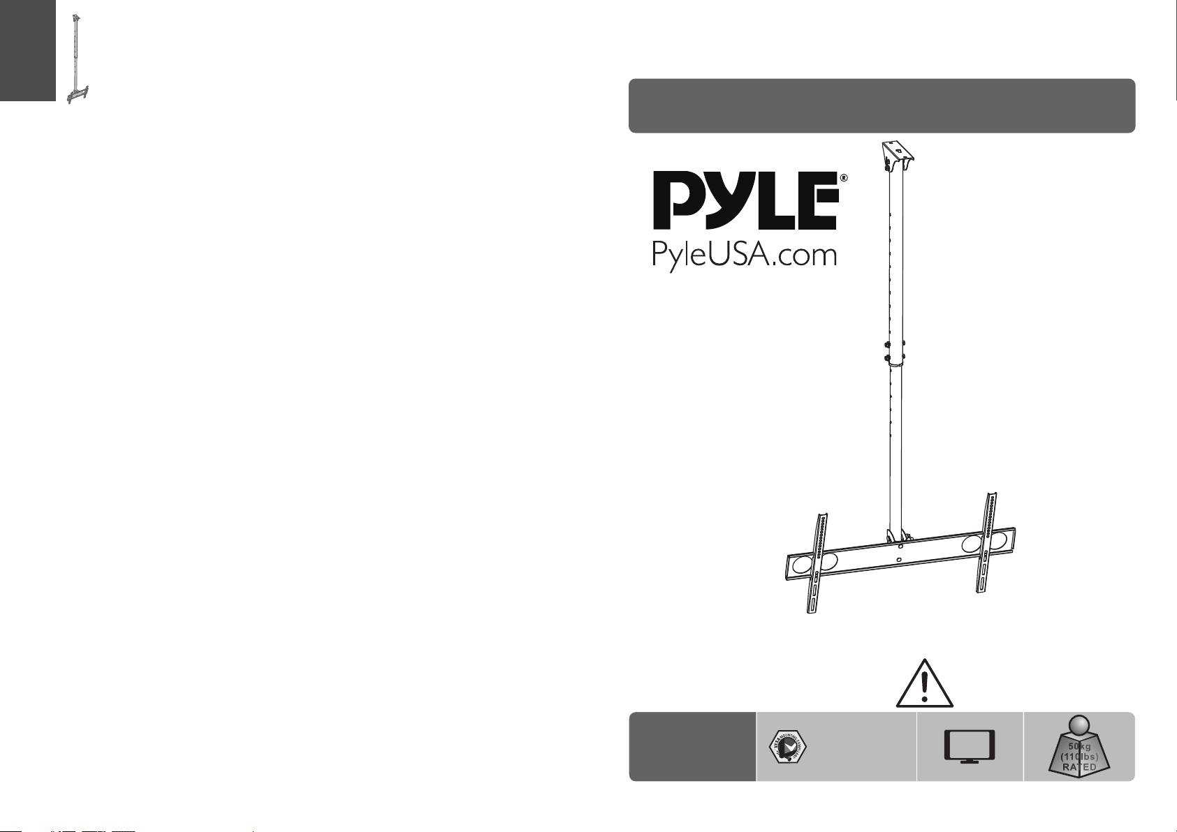
INSTALLATION MANUAL
Flat Panel Ceiling Mount
PCTVM18
/300x 300
200x2 00
400x4 00/ 400 x20 0
600x4 00/ 800 X40 0
CA UT ION: DO N OT EXCEED
RATE D LIS TED WE IGH T. SERI OUS
INJ URY OR P ROP ERTY DAMA GE
MAY OCCUR!
70"
MAX
50kg
50kg
50kg
(110lbs)
(110lbs)
(110lbs)
RATE D
RATE D
RATE D
Page 2
NOTE: Rea d the entire instr uction manual be fore you st art ins tallati on and as sembly.
WARNING
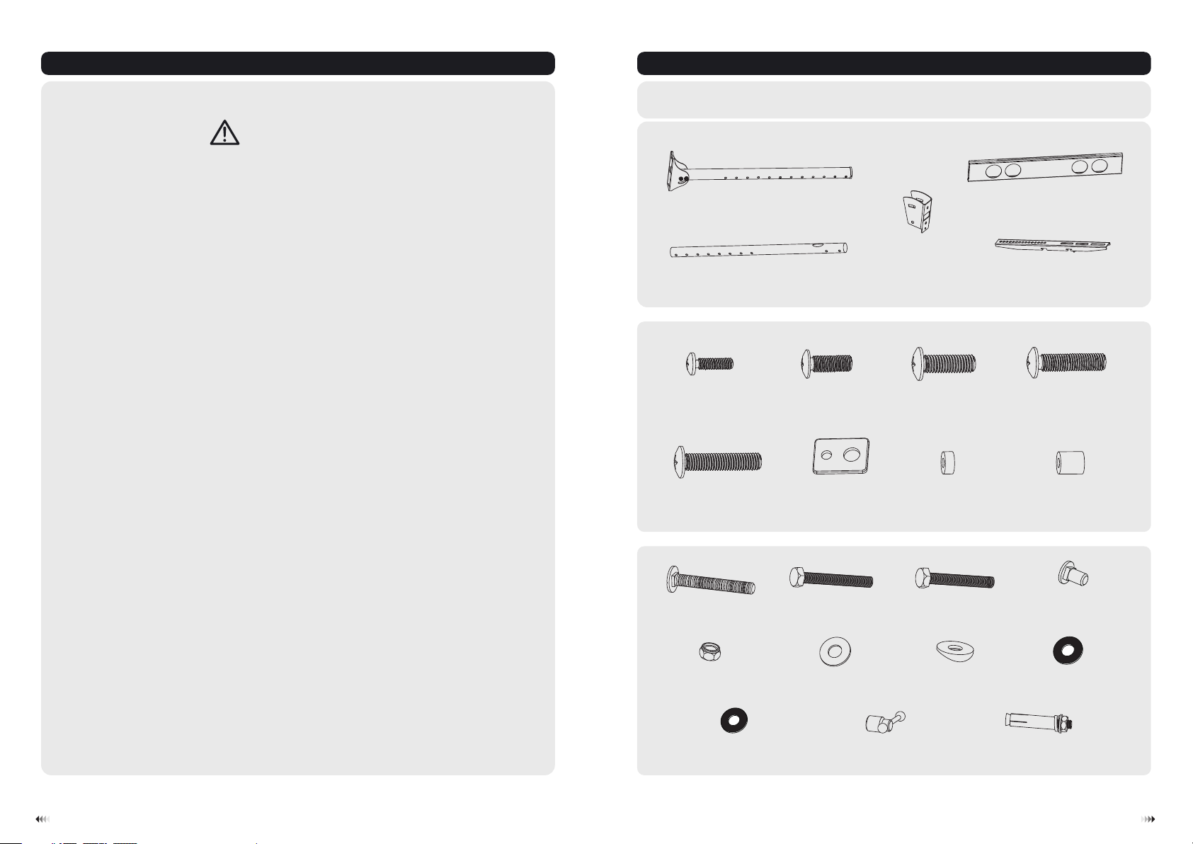
Component Checklist
IMPORTANT: En sure that y ou ha ve re cei ved all par ts ac cor din g to the comp one nt ch eck list prio r to in sta lla tion.
If an y par ts ar e mis sing or fau lty, t ele phone you r loc al di str ibutor fo r a rep lac eme nt.
• Do not begin the installation until you have read and understood all the instructions
and warnings contained in this installation sheet. If you have any questions
regarding any of the instructions or warnings, please contact your local distributor.
• This mounting bracket was designed to be installed and utilised ONLY as
specified in this manual. Improper installation of this product may cause damage
or serious injury.
• This product should only be installed by someone with good mechanical ability
who has basic building experience and fully understands this manual.
• Make sure that the supporting surface will safely support the combined weight of
the equipment and all attached hardware and components.
• Always use an assistant or mechanical lifting equipment to safely lift and position
the equipment.
• Tighten screws firmly, but do not over tighten. Over tightening can cause damage
to the items, This greatly reduces their holding power.
• This product is intended for indoor use only. Using this product outdoors could
lead to product failure and personal injury.
Package M
M5x14
M8x30
Package P
M8x60
top pip e (x1 )
A
conne ct pl ate ( x1)
botto m pip e (x1 )
B
(x4) M6x14
M-A
(x4) small s pac er
M-E
(x1) M8x60
P-A
(x4)
M-B
washe r
M-F
P-B
(x4)
(x1)
C
M8x20
M-C
M8x55
M-G
P-C
(x4)
(x2)
unive rsa l pla te (x 1)
adapt er br ack et (x 2)
(x8)
D
E
M6x30
(x4)
M-D
big spa cer
M-H
M8x14
P-D
(x4)
(x2)
P-E
x washe r
ø8.5 ø17.5 (x3)
P-I
D8 ø8.5 ø16 (x6)
x washe r M8 nut (x5)
P-F
M8 iron k nob
P-J
(x1)
washe r
P-G
(x4)
ø10.5 ø20 (x1)
x washe r
P-H
x70 iro n exp ans ion b olt
M8 (x3)
P-K
21
Page 3

2. Assembling the Universal Plate1b. Solid Brick and Concrete Block Mounting: 1. Assembling the Pipes
P-D
Run pow er ca ble t hro ugh pipe.
P-C
P-F
P-E
D
Attac h con nec t pla te to t he univers al pl ate u sin g correct combi nat ion o f scr ews, washers an d nut s.
C
P-F
P-E
P-J
P-E
P-F
P-F
P-I
P-I
P-H
P-G
P-A
P-B
P-G
P-I
Attac h bot tom p ipe t o top p ipe
and fix t hem a t the d esi red
heigh t. Us ing c orr ect
combi nat ion o f scr ew, washer
and nut .
Assemb le th e univers al pl ate and bot tom p ipe with co nne ct plate. Usin g cor rect comb ina tio n of screws
washer s, nu ts and iron k nob .
3
,
4
Page 4

1b. Solid Brick and Concrete Block Mounting: 1b. Solid Brick and Concrete Block Mounting:
3. For Solid Brick and Concrete Mounting
60mm
45mm
(2.4")
(1.8")
2
ø 12mm
(ø 1/2")
4.Installing the Adapter Brackets
4-1 For Flat Back Screens
TV
TV
TV
E
Not e: Ch oose the appropria te screws , washers
and s pac ers (i f necessary) a ccordin g to the
typ e of screen .
P-K
Drill three
pilot holes
Screw ceiling
mount on the
ceiling
M-A
M-B
M-C
M-F
1
4-2 For Recessed Back Screens or to Access A/V Inputs
· Pos ition the a dapter br ack ets as clos e as
pos sib le to th e center of t he displa y.
· Scr ew the adap ter brack ets onto th e display.
Tig hten all screws b ut do n ot ov er
tight en.
E
flat roof installation
Tig hten all nuts but d o not o ver
tight en.
sloped roof installation
M-G
M-C
M-F
TV
TV
TV
WARNING
Insta llers must verify t hat the supp ortin g surface wi ll safely su pport t he combine d weigh t
of the eq uipment an d all att ached hard ware and com ponen ts.
M-G
M-G
M-C
M-D
M-E
or
M-D
M-E
M-F
M-G
M-H
M-F
M-D
M-E
or or
M-F
M-H
65
Page 5

5. Hanging the TV onto the Universal Plate 6. Adjustment
Loose n the k nob a nd ad just to
the des ire d ang le, t hen tighten
it.
Attac h the TV onto the u niv ers al pl ate and
tight en th e saf ety s cre ws with a prop er
screw dri ver.
Make su re th e TV is safe ly se cur ed be fore
relea sin g.
0°
-15°
87
Page 6

Maint ena nce
• Check t hat t he br ack et is s ecure and sa fe to u se at r egu lar intervals (at l eas t eve ry three months ).
• Pleas e con tac t you r distributor i f you h ave a ny qu estions.
109
 Loading...