

Page 1

iGO My way 2006 Plus
Navigation software for PNA
UK English
June, 2007 (iGO PNA 1.1)
www.pyleaudio.com
Page 2

Copyright note
The product and the information contained herein may be changed at any time without prior
notification.
This manual nor any p arts thereof may not be reproduced or transmitted in any form either
electronically or mechanic ally, including photocopying and recording, without the express
written consent of Nav N Go Ltd..
Whereis® map data is © 2 007 Telstra Corporation Limited and its licensors
Data Source © 2007 Tele Atlas N.V.
Austria: © BEV, GZ 1368/2003
Denmark: © DAV
France: © IGN France
Great
Britain:
Italy: © Geonext/DeAgostini
Northern
Ireland:
Norway:
Switzerland: © Swisstopo
The
Netherlands
:
All rights reserved.
Ordnance Survey data with permission of Her Majesty’s Stationery
Office © Crown Copyright
© Ordnance Survey of Northern Ireland
© Norwegian Mapping Authority, Public Roads Administration /
Mapsolutions
Topografische ondergrond
Copyright © dienst voor het kadaster en de openbare registers,
Apeldorn
2
Page 3

Thank you for choosing iGO as your door-to-door in-car navigator. Read the Quick Start
Guide first and start using iGO right away. This document is the detailed description of the
software. Although iGO can easily be discovered by experience, it is still recommended that
you read through this manual to clearly understand the exact function of each button and
icon.
3
Page 4

Table of Contents
1 Warnings and safety information ................................................................................... 9
2 General information ..................................................................................................... 10
3 Operating iGO (Controls)............................................... ................................ .............. 11
3.1 Hardware buttons ................................................................................................ 11
3.1.1 Power on/off..................................................................... ............................ 11
3.1.2 Zoom in and out ........................................................................................... 11
3.2 Screen buttons and controls ................................................... ............................. 11
3.2.1 Direct selectors ....................................................................................... ..... 11
3.2.2 List selectors........................................ ................................ ........................ 11
3.2.3 Sliders.......................................................................................................... 11
3.2.4 Switches ...................................................................................................... 12
3.2.5 Switches in the Quick menu ............................................. ............................ 12
3.2.6 Virtual keyboards .................... ................................ ................................ ..... 12
3.2.6.1 ABC-type keyboards ................................................................................ 12
3.2.6.2 QWERTY-type keyboards ................................................................... ..... 13
3.2.6.3 The numeric keyboard ................ ................................ ............................. 14
4 Discovering the program through the screens ............................................................. 15
4.1 Main menu..................................... ................................ ...................................... 15
4.2 About screen ......................................................................... .............................. 16
4.3 The map ........................................................................................... ................... 16
4.3.1 2D and 3D map views ................. ................................ ................................. 16
4.3.2 Zoom levels ............................................................. ................................ .... 17
4.3.3 Daylight and night colour schemes ............................................... ............... 17
4.3.4 Streets and roads............ ............................................................................. 18
4.3.5 Other objects ........................................................... ................................ .... 19
4.3.6 Current position and Lock-on-Road.............................................................. 19
4.3.7 Selected map point, also known as the Cursor ... ................................ ......... 20
4.3.8 Marked map points (Pin) .............................................................................. 21
4.3.9 Visible POIs (Points of Inter est) ...................................... ............................. 21
4.3.10 Road safety cameras .................. ................................ ................................. 23
4.3.11 Elements of the Active Route ............................................. .......................... 23
4.3.11.1 The start point, via points and the destination....................... ................ 23
4.3.11.2 Animated turn guidance ............................................................ ........... 23
4.3.11.3 The active leg of the route ........... ................................ ......................... 23
4.3.11.4 Inactive legs of the route ............... ................................ ....................... 24
4.3.11.5 Roads in the route excluded by your preferences................................. 24
4.4 GPS Data screen............................................................... ................................ .. 25
4.4.1 GPS data displayed .............................................. ................................ ....... 25
4.4.2 GPS connection indicator............ ................................ ................................. 25
4.4.3 GPS data quality indicator............................................................................ 26
4.4.4 Time sync hronization .......... ......................................................................... 26
4.5 Screens with map ................................................................................................ 27
4.5.1 Turn preview (No. 1) ............................................................................ ........ 29
4
Page 5

4.5.2 Zoom in and out (No. 2 & 3) ....................................... ................................ .. 31
4.5.3 Tilt up and down (No. 4 & 5) ......................................................... ............... 31
4.5.4 Follow mode - loc k to GPS position and heading (No. 6) .................... ......... 31
4.5.5 Cursor (No. 7) ............. ................................ ................................ ................. 32
4.5.6 Map scale (No. 8).................................................. ....................................... 32
4.5.7 Menu (No. 9) ................................................. ................................ ............... 32
4.5.8 Map orientation and Overview (No. 10) ................................... ..................... 32
4.5.9 GPS position quality (No. 11) ....................................................................... 33
4.5.10 Battery status (No. 12) ...................................................... ........................... 34
4.5.11 Sound muting (No. 13) ................................................. ................................ 34
4.5.12 Track Log recording/playback indicator ( No. 14) .......................................... 34
4.5.13 Cursor menu (No. 15) ................................ ................................ .................. 35
4.5.14 Current street (No. 16) ................................................................................. 36
4.5.15 Travel and Route data (No. 17)........... ................................ ......................... 36
4.5.16 Distance to next turn (No. 18) ........... ................................ ........................... 37
4.5.17 Next street / Next settlement (No. 19) .......................................................... 37
4.5.18 Approaching next turn (No. 20) .................................................................... 37
4.6 Route Information screen ........................ ................................ ............................ 37
4.6.1 Route data displayed (for destination and via points) ................................... 37
4.6.1.1 Route line ..................................... ............................................................ 38
4.6.1.2 Distance Left ............................................................ ................................ 38
4.6.1.3 Method ............................ ................................ ......................................... 38
4.6.1.4 Time Left ...................................................... ................................ ............ 39
4.6.1.5 Estimated Arrival ...................................................................................... 39
4.6.1.6 Destination / Via point .......................................... ................................ .... 39
4.6.2 Warning icons ................................................................... ........................... 39
4.6.3 Fit to screen .................................. ................................ ............................... 40
4.6.4 Parameters ................. ................................ ................................ ................. 40
4.7 Menu ................................................................................... ................................ 40
4.7.1 Find tab ....................................................................... ................................. 40
4.7.2 Quick tab ...... ................................ ................................ ............................... 40
4.7.2.1 3D Map (switch) ............. ................................ ................................ .......... 41
4.7.2.2 Zoom & Tilt (switch) ......... ................................ ................................ ........ 41
4.7.2.3 Night Mode (switch) ................................................................................. 41
4.7.2.4 Manage POI (Points of Interest) ........................................................... .... 42
4.7.2.5 Popup Information (switch).................................... ................................ ... 45
4.7.2.6 Manage Track Logs ................................................................................. 45
4.7.3 Route ta b .................................................................................. ................... 47
4.7.3.1 Recalculate ............................................................ ................................ .. 47
4.7.3.2 Delete ............................................................................... ....................... 49
4.7.3.3 Itinerary ............................................... ................................ ..................... 49
4.7.3.4 Fly Over .......................................................... ................................ ......... 50
4.7.3.5 Edit .............. ................................ ................................ ............................ 50
4.7.3.6 Info............................................. ................................ .............................. 51
5
Page 6

4.7.4 Main button ........................... ................................ ................................ ....... 52
4.8 TMC (Traffic Message Channel) ....................................................................... ... 52
4.8.1 List of TMC messages ................................................................................. 52
4.8.2 TMC cont rol centre ............................................ ................................ .......... 52
4.8.2.1 Selected FM radio station................ ................................ ......................... 53
4.8.2.2 Exclude s elected station........................................................................... 53
4.8.2.3 Show exc luded stat ions............................................................................ 53
4.8.2.4 Sort events by distance / type ............................................................. ..... 53
4.8.2.5 Use traffic information ......................... ................................ ..................... 53
4.8.2.6 Recalculate to avoid traffic ................................. ................................ ...... 53
4.9 Road safety cameras ............................................................................ ............... 54
4.9.1 Camera types .......................... ................................ ................................ .... 54
4.9.1.1 Fixed cameras .......................................................... ............................... 54
4.9.1.2 Mobile cameras...................................................... ................................ .. 54
4.9.1.3 Built-in cameras ....................................................................................... 55
4.9.1.4 Section control cameras...................... ..................................................... 55
4.9.1.5 Red light cameras .................................................................................... 55
4.9.2 Controlled traffic direction ..................................... ....................................... 55
4.9.3 Speed limit checked ..................................................................................... 56
4.9.4 Add a new camera or edit an existing one.................................................... 56
4.9.5 Change the settings of the camera warning ................................................. 56
5 Settings ............................................................................. ................................ ......... . 57
5.1 General settings ......................... ................................ ......................................... 57
5.1.1 Safety Mode....................................... ................................ .......................... 57
5.1.2 Set Favourite Destinations ............................................. .............................. 57
5.1.3 Automatic Night Colours ..................................................... ......................... 58
5.1.4 Alerts ............................................................................... ............................ 58
5.1.4.1 Warn When Speeding ......... ................................ ................................ ..... 59
5.1.4.2 Enable Safety Cameras ........................................................................... 60
5.1.5 Route Recalculation ....................... ................................ .............................. 60
5.1.5.1 Automatic ............. .................................................................................... 60
5.1.5.2 Ask First ............................................................................ ....................... 61
5.1.5.3 Disabled .... ................................ ................................ ............................... 61
5.2 Map settings ............................................ ............................................................ 61
5.2.1 Daylight / Night colour profile ..................... ................................ .................. 61
5.2.2 Alternative Road Names .............................................. ................................ 62
5.2.3 Show Street Labels ................................ ................................ ...................... 62
5.2.4 Textured Polygons ....................................................................................... 62
5.3 Sound settings................................................... ................................ .................. 62
5.3.1 Master sound volume/switch ........................................................................ 62
5.3.2 Voice guidance v olume/switch ..................................................................... 62
5.3.3 Key sound volume/switch........................................................ ..................... 63
5.3.4 Dynamic Volume............................................................... ........................... 63
5.3.5 Attention Tone ........................... ................................ ................................ .. 63
6
Page 7

5.4 Route parameter settings .................................. ................................ .................. 63
5.4.1 Method........... ................................ ................................ .............................. 64
5.4.2 Route ........................................................................................................... 64
5.4.2.1 Short ............. ................................ ................................ ........................... 64
5.4.2.2 Fast. ................................ ................................ ................................ ......... 64
5.4.2.3 Economical .................................. ................................ ............................ 64
5.4.3 Vehicle ......................................................................................................... 64
5.4.4 Road ty pes to include/exclude ............. ................................ ........................ 65
5.4.4.1 Unpaved Roads ..................... ................................ ................................ .. 65
5.4.4.2 Motorways ............................................................................................... 65
5.4.4.3 Ferries.................................................................................................. .... 65
5.4.4.4 U-turns ......................................................... ................................ ............ 65
5.4.4.5 Permit needed................................... ....................................................... 65
5.4.4.6 Toll Roads ................................................................................................ 65
5.5 Language & Units ............................................................................ .................... 65
5.5.1 Program language .......................... ................................ ............................. 66
5.5.2 Voice language ............................................................................................ 66
5.5.3 Units ...................................................................... ................................ ...... 66
5.5.4 Set Date & Time Format ..................................... ................................ ......... 66
5.6 Advanced settings ................... ................................ ................................ ............ 66
5.6.1 Display options ............................................................................ ................ 67
5.6.1.1 2D in Map mode (and North-up orientation) ............................................. 67
5.6.1.2 3D in Cockpit mode (and track-up orientation) ......................................... 67
5.6.1.3 Zoom in after find .............................. ................................ ....................... 67
5.6.1.4 Coordinate display format ........................................................................ 68
5.6.1.5 Cockpit screen layout ............................................................................... 68
5.6.2 Backlight settings .............................................................................. ........... 68
5.6.2.1 Power management ........................................... ................................ ...... 68
5.6.2.2 Brightness ................................ ................................................................ 68
5.6.3 Smart Zoom ............................................... ................................ .................. 68
5.6.3.1 Smart Zoom settings ................................................................................ 69
5.6.3.2 Enable Ov erview mode ............................................................................ 69
5.6.3.3 Restore Lock-to-Position and Smart Zoom............................................... 69
5.6.4 Route options... ................................ ............................................................ 70
5.6.4.1 Off-route sensitivity and Recalculation delay ..................... ....................... 70
5.6.4.2 U-turn penalty .......................................................... ................................ 71
5.6.4.3 Cross-border planning............................................................. ................. 71
5.6.4.4 Carpool lanes (for the USA map only) ...................................................... 71
5.6.4.5 Keep pos ition on road (Lock-on-Road) .................................... ................. 71
5.6.5 User data management...... ................................ ................................ .......... 71
5.6.5.1 Backup Data .......................................................................... .................. 71
5.6.5.2 Restore Data....................... ................................ ..................................... 72
5.6.5.3 Remove Pins....................................................................... ..................... 72
5.6.5.4 Clear Dat a .................................................................... ............................ 72
7
Page 8

5.6.5.5 Reset Advanced Settings ......................................................................... 72
6 Find ..................................... ................................ ................................ ..................... ... 73
6.1 Find & GO (Main menu)................................. ................................ ...................... 73
6.2 Selection by tapping the map......... ................................ ................................ ...... 73
6.3 Using the Find menu................................................................................ ............ 73
6.3.1 Find an Address, Street, Intersection or City .......................... ...................... 73
6.3.1.1 Selecting the city, state and country to search in...................................... 74
6.3.1.2 Selecting a street or the centre of the settlement ..................................... 77
6.3.1.3 Selecting a house number or the midpoint of the street ............................ 78
6.3.1.4 How to select an intersection instead of a house number ......................... 79
6.3.1.5 An example for a full address search ....................................................... 79
6.3.2 Find in History ................................................. ................................ ............. 80
6.3.3 Find Coordinates... ................................ ................................ ....................... 80
6.3.4 Find a POI.................................................................................. .................. 81
6.3.5 Find one of the Favourites (Home/Work) .......... ................................ ........... 83
7 Troubleshooting guide ............................................................................. .................... 84
8 Glossary ............................................................................. ................................ ......... 85
9 End User License Agreement...................................................................................... 88
8
Page 9

1 Warnings and safety information
iGO is a navigation system that helps you find your way to your selected destination. It will
determine your exact location with the help of the built-in GPS device. The position
information obtained from the GPS receiver will not be transmitted anywhere, so others will
not be able to track you by the help of this program.
If you are the driver of the vehicle, we recommend that you operate iGO before beginning
your journey. The driver’s attention s hould always be on the road. Plan your route before
departure and pull over if you need to change route parameters. iGO has a built-in (optional)
Safety Mode that will prevent you from using the screen functions if your car is in motion.
Unless a passenger will be the only one to operate iGO, we strongly encourage y ou to turn
on the Safety Mode.
It is also important that you look at the display only if it is absolutely safe to do so.
You should always observe traffic signs and road geometry before you obey any instruction
from iGO. If you n eed to deviate from th e recommended direct ion, iGO will suggest a
modified route according to the new situation.
Never place th e PNA where it can obstruct the view of the driver, is within the deployment
zone of airbags, or where it can cause injuries in case of an accident.
For further information, please consult the End User License Agreement: Page 88.
9
Page 10

2 General information
iGO is a navigation system optimised for in-car use. It provides door-to-door navigation for
both single and multi-point routes using adaptable route parameters. iGO is capable of
planning routes throughout the whole installed map set. Unlike some other products, iGO
does not require that you change maps or switch to a poorly d etailed general map to
navigate between map segments or countries. You always have complete freedom to go
wherever you wish. Just select your destination and go.
You do not need a stylus to us e iGO. All screen buttons and controls are designed so that
you can operate them with your fing er tips.
You can access all fun ctions of the program by using hardware and screen buttons. With the
help of these buttons you can travel through all the screens of the program. Most of the
screens (especially menu functions and settings) c an be accessed from several other
screens, minimising the number of actio ns needed to reach the desired function.
When using iGO, you do not need to ‘double tap’ or ‘tap & hold’ the touch screen as these
functions cannot be used reliably in a moving vehicle. A single tap triggers most of the
screen controls. The only exceptions are ‘drag & drop’ for moving the map, or scaling it in
Map mode (Page
32).
Most of the screens have a Return button
the previous scree n or direc tly to one of the map screens.
Settings screens also have a Help button
detailed description of the current settings screen.
in the top left corner. This arrow returns to
in the top right corner. This will s how a
10
Page 11

3 Operating iGO (Controls)
iGO is designed for easy o peration. All controls are operable by fingertips. Wherever
possible, pushbuttons and lists are provided to make accessing f unctions or changing
settings as easy as possible.
3.1 Hardware buttons
There are only a few hardware buttons on your PNA.
The majority of the iGO functions can be accessed using the touch screen. The hardware
buttons are the following:
3.1.1 Power on/off
Use this button to turn the power of the PNA on or off any time.
If the device power is turned off while iGO is running, when you turn the device back on, iGO
will continue the navigation as soon as the built-in GPS determines the location again.
While the device is switched off, the GPS will not work, no position will be calc ulated, track
log will not be saved, and navigation will stop.
3.1.2 Zoom in and out
Zoom will change the scale of the map in both 2D and 3D map modes. This function is
explained in detail here: Page
Note: When applied on list and menu screens, this action will move the highlight up and
down.
3.2 Screen buttons and controls
The primary input channel of iGO is the touch screen. If you read on, you will realise that
most parts of the screen are not only used to display information but also to initiate fu nctions
by tapping. Below you will find a list of the most frequently used controls in the program.
3.2.1 Direct selectors
Some of the settings can be chosen from a short list of possible values. If the values can be
described graphically, all values are avail ab le on the screen.
31.
Tap one of the icons to set/change the value.
3.2.2 List selectors
When the values in the list need to be named, only the current valu e is shown (sometimes
together with a short description) in a horizontal stripe with arrows at both ends.
The arrows are buttons. Tap to move left in the list or tap to move right.
You need not confirm your selection. As soon as you leave the screen, the selec ted value
becomes effective.
3.2.3 Sliders
When a feature has several different unnamed (numeric) values, iGO will show sliders that
look like analogue potentiometers to set the desired value.
If the value limits are not displayed at the ends of the slider, the leftmost position means t he
minimum value, while the rightmost position represents the maximum value.
With most sliders you can check the current value on the left.
11
Page 12

This control can be operated in two ways. Either drag the handle to move the slider to its
new position, or tap the slider where you want the handle to a ppear (the thumb jumps there
immediately). As with the list selectors, there is no need to confirm your selection. As soon
as you leave the screen, the selected value becomes effective.
3.2.4 Switches
When a function can only h ave two values (mainly Enabled and Disabled), a switch is used.
Unlike with list selectors, the horizontal line contains the name of t h e function and not the
actual status. There is a lamp on the left to show whether the function is active or not.
When the lamp is dark , the function is not selected. When it is lit , the function is
enabled. The whole strip works as a button. Tap anywhere to toggle between the enabled
and disabled status.
3.2.5 Switches in the Quick menu
The switches of the Quick menu (Page
different in order to fit in with the other menu buttons.
Tap the button to toggle between the enabled and disabled states.
3.2.6 Virtual keyboards
iGO is designed in a way that you only need to enter letters or numbers when it is inevitable.
In these cases a full screen keyboard pops up that can easily be operated with your
fingertips. You can choose between a separate ABC and numeric keypad, or a set of
QWERTY-type keyboards that contain both letters and numbers. iGO will remember your
last choice and offer it the next time you need to enter data.
The alphabetic keyboards in iGO do not contain special characters, because you do not
need to enter accents when searching for a destination. Type only the base letters (the letter
most similar to the accented one) and iGO will search for all their combinations in the
database (e.g. fo r the French street ‘Cité Bergère ’ you only need to type ‘Cite Bergere’, and
the rest is done by the program).
When you type in POI or track log names, iGO will automatically turn all initials into capitals
to create names that look pleasant.
3.2.6.1 ABC-type keyboards
These keyboards contain only letters (Latin, Hebraic, Greek or Cyrillic). If you wish to enter
40) behave as normal switches but they look
numbers, you need to tap the Keys button to switch to the numeric keyboard.
Use Backspace (arrow pointing left) to delete the last letter you have entered if you have
made a mistake, tap Space to enter more words, and hit Done to finish entering the text.
12
Page 13

This type of keyboard has large, finger-friendly buttons.
Note: If you have chosen a program language that uses Latin letters, only the ABC keyboard
appears. If you choose the Greek language, an additional keyboard appears with Greek
letters. Similarly Hebraic and Cyrillic letters are available when Hebrew or Russian is chosen
in Setup / Languages (Page
If you are used to computer keyboards, you may consider trying one of the QWERTY-type
keypads.
3.2.6.2 QWERTY-type keyboards
QWERTY-type keyboards have both letters and numbers on them. Their layout is the same
as of the standard QWERTY, QWERTZ (German) and AZERTY (French ) keyboards. To
switch to your desired QW ERTY-type keyboard, press the Keys button r epeatedly until th e
appropriate keyboard appears.
66).
13
Page 14

The special keys described in the previous section are also available here.
3.2.6.3 The numeric keyboard
The numeric keyboard only contains number s, on huge buttons. The special keys you find
on the other keyboards (except Space) are available here as well.
Although QWERTY-type keyboards als o contain number keys, whe n entering a house
number, the program offers the more convenient numeric keypad.
14
Page 15

4 Discovering the program through the screens
The best way to discover iGO is to explore each screen in detail, and to find out how to
move from one to another. Read this chapter for a guided tour.
4.1 Main menu
iGO st arts by displaying the Main menu. This is the root of the screen hierarchy, but you
need to return here very rarely while using the program. Screens are also access ible from
each other to reduce the number of actions needed to initiate a function or change a setting.
Most parts of the program are directly accessible from here by using the buttons described
below.
No. Content
1 iGO logo
2 Battery Status in di cator
3 Button to open Cockpit screen
4 Button to open Find menu
5 Button to open Settings
Button that displays GPS Status and opens the GPS Data
6
screen
7 Button to minimise iGO (navigation wil l not stop*)
8 Current position
9 Current date and time
10 Button to open Map screen
11 Button to open About screen
12 Button to exit iGO** (navigation sto ps)
* Depends on program settings
** Same as removing the SD card
15
Page 16

4.2 About screen
Tap About on the Main menu screen to open this screen. The About screen is not used in
normal navigation. It is there to inform you about the map licenses you have, the creators of
iGO and the legal aspects of using the program.
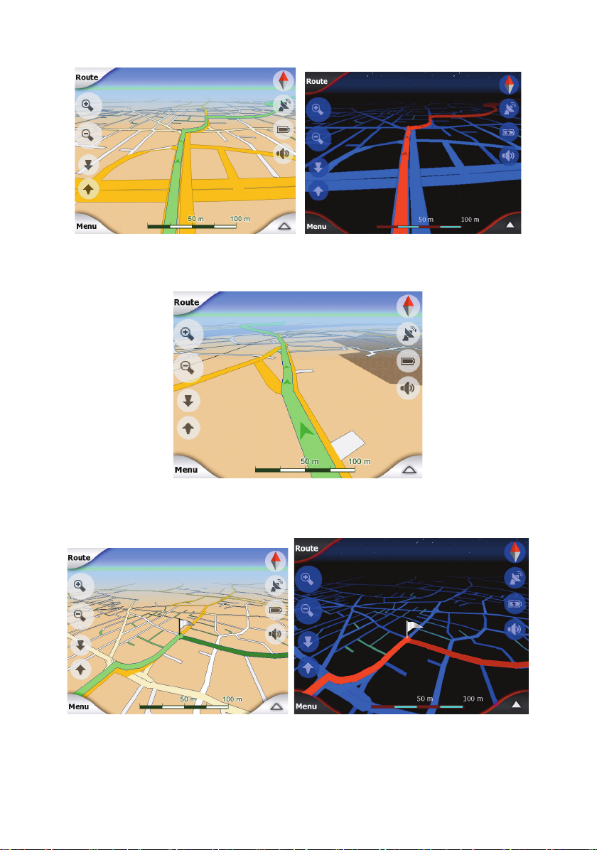
4.3 The map
The most import ant and most frequently used screens of iGO are the two screens with the
map (Map screen and Cockpit screen). They are similar in lo ok and in possible controls but
are optimised for dif ferent uses. The ma p they display is common. The elements of the map
are described here. For the controls and special functions of the two map screens see Page
27.
The current version of iGO is primarily intended for land navigation. That is why maps in iGO
look similar to paper roadmaps (when using daytime colours and 2D map mode). However,
iGO provides much more tha n regular pa pe r maps can. The look and the contents can be
changed.
4.3.1 2D and 3D map views
Besides the classical top down view of the map (called 2D mode), you have the possibility to
tilt the map to have a perspective view (3D mode) that gives a view similar to that seen
through the windscreen with the possibility to see far ahead.
16
Page 17
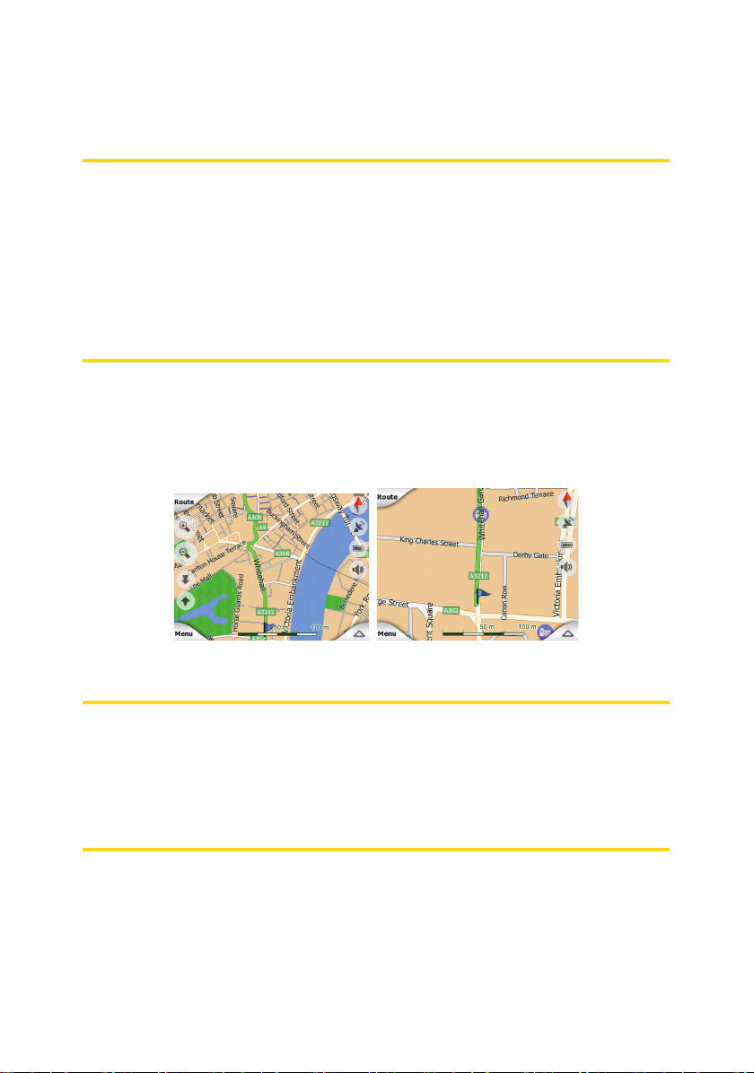
It is easy to change between 2D and 3D modes. You have two options. You can use the Tilt
up and down buttons (Page
you can use the switch in the Quick menu (Page
modes.
Note: You may find that 2D mode is more useful in North-up Map mode when looking for a
certain part of the map or an object to select as destination. On the other hand, 3D mode in
Track-up Cockpit mode with Smart Zoom makes navigation very comfortable. The
description of these modes will come later in this manual.
Note: 3D view is only useful for navigation. As you zoom out, the view angle will
automatically be raised. Finally 2D view will be reached. When you zoo m back in, 3D view
will gradually return.
Note: Using the Advanced settings, yo u can force Cock pit mode to always start in 3D Trackup view (Page
enter this screen, the preset look will reappear. Similarly you can fo rce Map mode to always
start in 2D North-up view.
4.3.2 Zoom levels
iGO uses high quality vector maps that let you see the map at various zoom levels, always
with optimised content (the density of the map details can be independently set for Map and
Cockpit screens in Map settings (Page 61). Street names and other text objects are always
displayed with the same font size, never upside down, and you only see as many streets an d
objects as nee ded to find your way around the map. Zoom in and out to see how the map
changes in either the 2D or 3D view.
67). You can still rotate and tilt the maps in either mode, but the next time you
31) to tilt the map seamlessly between 2D and all 3D angles, or
41) to quickly switch between the two
Changing the scale of the map is very easy. You can drag and stretch the scale (Page 32) at
the bottom of the Map screen, or use the zoom icons (Page
screens.
Note: If you need to zoom out briefly to locat e your position on the map, use the Overvie w
mode instead of zooming out and back in. The Overview mode is a 2D North-up v iew that
can be started by tapping the compass button on the right (Page
Note: iGO has a special Smart Zoom function for navigation that automatically rotates,
scales and tilts the map in 3D map mode to always give you the optimal v iew in your current
situation. When approaching a turn, it will zoom in and raise the view angle to let you easily
recognise your ma noeuvre at the next junction. If the next turn is at a distance, it will zoo m
out and lower the view angle to flat in order to let you see the road in front of you.
4.3.3 Daylight and night colour schemes
The different colour schemes let you adjust iGO to the brightness of the environment. Use
the daylight and night colour schemes accordingly. Daylight colours are similar to paper
roadmaps, while the night colour schemes use dark tints for large objects to keep the
average brightness of the screen low, with carefully selected colours to still keep you
informed about all the necessary information on the screen.
31) on both Map and Cockpit
32).
17
Page 18

You can change between day and night views manually in the Quick Menu (Page 41) or let
iGO do it automatically (Pa ge
Note: The automatic day/night mode is based upon the current date and GPS position by
which iGO calculates the exact sunrise and sunset times on the particular day at the
particular location. Using t hat information iGO can automatically sw i tch between the colour
schemes a few minutes before sunrise, when the sky has already turned bright, and a few
minutes after sunset before it gets dark.
Tip: There are several day time and night colour schemes included with iGO. To select the
one that suits your needs the best, make your selection in Settings (Page 61 ).
Tip: To further enhance the effect of the night colour scheme, you can instruct iGO to
decrease the display backlight when the night colours are used. Set the desired backlight
levels for both daylight and night modes. Page
Note: T he colours mentioned and screenshots included in this manua l refer to the default
daytime and night colour schemes. They may not look the same in the schemes you have
chosen.
Tip: If you use iGO after sunrise or before sunset, look for the sun in the sky in the map
background using a flat 3D view. It is displayed at its actual pos ition to give you another wa y
to orientate, and also to provide some eye candy.
58) for you.
68.
4.3.4 Streets and roads
The similarity of iGO to paper roadmaps is also convenient when it comes to streets, the
most important elements of the map concerning nav igation. iGO uses similar colour codes to
those you are accustomed to, and the width of t he streets also refers to their importance, so
it will not be difficult to tell a highway from a small street.
Streets and roads have names or numbers for identification. Of course, this information can
be displayed on the map. iGO uses two different ways to show street labels. The
18
Page 19
conventional way is th e same as a roadmap – it displays the n ame of the street aligned with
the street. The alternative is a kind of virtual signpost stuck into the street itself.
You need not choose between the two modes. iGO will use the one best for the current tilt
and zoom level. Zoom in to have only a few streets on the map, and start tilting up and down
to see how iGO switches between the two modes in an instant.
Note: The automatic switching is on ev e n when using Smart Zoom. At first you may find it
odd, but later you will discover how it adjusts the displayed information to the current view of
the map. It is important, as the driver must be able to read th e map at a glance.
Tip: If you do not want to be bot hered by street names during navigation, turn them off in
Map Options (Page 62).
Tip: Major roads usually have alternative names (numberin g) besides the primary name. You
can choose whether to display these alternative names or not. You can set this in Map
Options (Page
4.3.5 Other objects
To help orientate you, the map also contains objects that have no other navigating function
than to help you recognise your location on the map. These are surface-waters, large
buildings, forests, etc.
Tip: These objects are normally displayed using textured polygons that look natural to the
eye. You may wish to switch the textured display off (Page 62) to free some of the resources
of your PNA by replacing textures with plain coloured surfaces.
62).
4.3.6 Current position and Lock-on-Road
When your GPS position is available, a blue arrow (yellow when using night colours) shows
your location on the map.
19
Page 20

The direction of the arrow represents your heading. The arrow is sized and vertically rotated
with the zoom and tilt levels to always look re alistic.
iGO has a built-in Lock-on-Road feature that always puts the position arrow on the road, on
the axis of the street in case of one-way streets, or on the side of the road where you drive
(e.g. on the right in Germany and on the left in the U.K.) on two-way roads.
The location received from the GPS receiver is s hown as a blue dot on the map. This can
help you locate your position if the GPS accuracy is poor, and the Lock-on-Road system
puts you on the wrong street. It is also the location saved in the track log (Page 45).
Note: The Lock-on-Road feature can be turned off in Advanced settings (Page
pedestrian use. When switched off, the a rr ow is displayed at the position reported by the
GPS receiver.
When the GPS position is lost, the arrow turns grey, but the journey continues on the
recommended route for a short period of time with the speed last detected before the GPS
position was lost. When the next route event is reached, or aft er 40 seconds, the arrow
stops, and remains grey until GPS reception returns. This way short tunnels can be crossed
without losing the position.
4.3.7 Selected map point, also known as the Cursor
If you tap the map somewhere or select a specific item in Find, it will become the selected
point on the map, marked with a small red dot and permanently radiating red circles to make
it conspicuous at all zoom levels, even when it is in the background of a 3D map view. You
can use this point as starting point, via point, or destination of your route, you can search for
a POI near to it, mark it with a drawing-pin, or save it as a POI. The cursor, when visible, is
also the reference point for map scaling.
71) for
Note: When your GPS position is available, and Lock-to-Position (Page 31) is active, the
cursor is the current GPS positi on, the blue arrow. When you select another point by tapping
the map, or using the Find menu (Page
red dot and the radiating red circles.
73), the new Cursor is shown on the display with the
20
Page 21

4.3.8 Marked map points (Pin)
The Cursor can be marked with a Pin. Pins are shown as being stuck in the map. A Pin is
visible at all zoom levels and remains in its position until you unpin it, or delete all Pins in
Advanced settings (Page
72).
The colour of the Pin is automatically selected by iGO. Different colours help you identify a
Pin in the History list (Pa ge
GPS Coordinates.
Tip: There is a quick way to save the current GPS position as a Pin. Press the Record button
(hardware button with an audio cassette icon on it) to save the Pin instantly.
Tip: A quick way to tell the coordinates of a location you found on the map is to Pin it, and
then look for the coordinates in the History list (Page
coordinates with the Pin for later reference. If you do not need the coordinates later, just
select the point and start Find Coordinates (Page
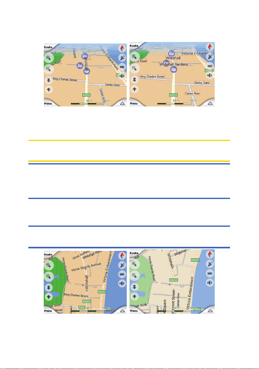
4.3.9 Visible POIs (Points of Interest)
iGO comes with thousands of built-in POIs, and you can create your own POI database as
well. Having all of them displayed on the map would make the map too crowded. To avoid
this, iGO lets you select which POIs to show and which ones to hide (Page
categories and subca tegories.
POIs are represented by icons on the map. For a built-in POI it is the icon of the subcategory
of the actual POI. For points y ou create, it is the icon you had chosen when you created the
POI (it can be changed later).
These icons are large enough to recognise the symbol, and semi-transparent so as not to
cover the streets and junctions behind them.
80) later. There they are shown together with their address and
80).This way you also save the
80).
42) using their
21
Page 22
When the map is zoomed out, the icons are not shown. As you zoom in, small dots appear
at the locations of visible POIs. Zoom ing in further makes the full icons appear.
If two points are too close to each other so that icons overlap, a multi-POI icon is
shown instead of individual ones. Zoom in more to see them separately. (Should the two
POIs have the same icon, this icon will be displayed instead of the multi-POI icon.)
Note: When navigating, POI icons can be disabled together with street names (Page
you still need this information during your journey, just drag the map to disable Lock-toPosition (Page
to reactivate Lock-to-Position.
31). This will restore street names and POI icons immediately. Now tap Lock
62). If
Tip: Tap the map on or near a POI item to see the list of the names of the nearest POIs in a
popup list, if it is enabled (Page 45). To see the details of a particular POI in the list, tap the
blue ’i’ icon on the right. If you have too may POIs nearby, this list may not be complete. In
the Cursor menu (Page
35) there is a button called POI that leads you to the screen of all
22
Page 23
nearby POI items. There you can open them one by one to see their details, and select any
of them as a route point.
4.3.10 Road safety cameras
Road safety cameras, such as speed cameras and red light cameras are special POI types
in iGO. They are described in detail here: Page
4.3.11 Element s of the Active Route
iGO uses a multi-destination routing system in which you have a start point (your current
location if GPS position is available), a destination, the line of the active leg of the route, and
optionally via points and inactive legs. They are all shown on the map.
4.3.11.1 The start point, via points and the destination
These points are represented by flags.
54.
4.3.11.2 Animated turn guidance
Animated arrows represent all ro ute events other than the above-mentioned special poi nts.
These arrows show the direction in which you need to continue your journey.
4.3.11.3 The active leg of the r oute
The active leg is the section of the route you are currently driving. If you have not added any
Via points, the whole route will be the active leg. When Via points are present, the active leg
is the part leading from your location to the next via point.
The active section is displayed in light green / red . It is always the most conspicuous part of
the map even when in the backgr ound of a 3D map view.
23
Page 24
The line of the route is displayed on the driving side of the road for two-way and on the axis
in case of one-way streets. When the map is zoomed in and the line is wide enough, small
arrows show the direction of the route. This can be useful if you preview the route before
starting the journey or whe n entering a complex junction.
4.3.11.4 Inactive legs of the route
Future sections of a route are inactive. They are also shown on the map with the same
colour but a darker tint than the active one. An inactive route sectio n becomes active as
soon as you reach its starting Via point.
4.3.11.5 Roads in the route excluded by your preferences
Although you can choose whether to include or avoid some road types in Route parameter
settings (Page
or the destination.
65), sometimes they are im possible to avoid near the starting point, via points
24
Page 25
If so, iGO will display those segments of the route with an alternate colour.
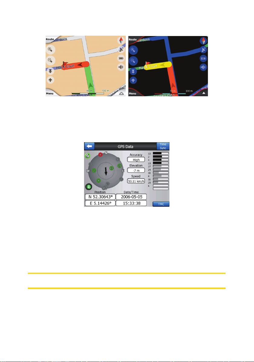
4.4 GPS Data screen
Tap the small satellite dish icon on the Main menu, Map or Cockpit screen to open this
window.
The GPS Data screen is a collection of information received from the GPS device and it also
serves as the entry point to the following screens:
• TMC,
• Time Sync.
4.4.1 GPS data displayed
The virtual sky on the left represents the currently visible part of the sky above you, with your
position as the cen tre. The satellites are shown at their curr en t positions. The GPS receives
data from both the green and grey satellites. Signals from the grey satellites are only
received, wh ile green ones are used by the GPS to calculate your current location. On the
right you can see the satellite signal strength bars. Grey bars are for the grey and black bars
are for the green satellites. To identify satellites use their numbers also shown in the virtual
sky. The more satellites your GPS tracks (the green ones), the better y our calculated
position will be.
Additional pieces of information on this screen are: current position in latitu de /longitude
format, elevation, speed, date, time and calculated accuracy.
Note: Accuracy can be affected by s everal factors the GPS cannot take into account. Use
this accuracy information only as estimation.
There are two icons on the left to show the status of the GPS connection and the quality of
reception.
4.4.2 GPS connection i ndicator
In the middle to the left there is a lamp si milar to the ones used for switches. This one has
more colours and represents more values:
25
Page 26
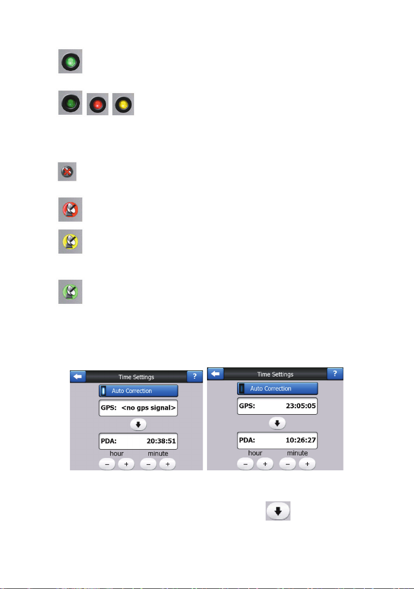
• a fast blin king green lamp means that there is communication with the GPS and
data is being received,
• other colours may not appear with a built-in GPS. Should any of
these appear, this means a faulty operation of your device.
4.4.3 GPS data quality indicator
In the top left corner there is a satellite dish to show the quality of the GPS position. Different
colours represent different signal quality:
• black with a red cross me an s there is no con nection with the GPS device. This
should never be the case if your device has a built-in GPS.
• red means the GPS is connected but no GPS position is available,
• yellow means 2D rec eption. A GPS position has been acquired, iGO is ready for
navigation, but the GPS is using enou gh satellites for calculating the horizontal position
only. Elevation data is not provided, and the position error may be significant.
• green means 3D reception. The GPS receiver has enough satellites to calculate
altitude. Position is generally c orrect (yet it can still be inaccurate due to different
environmental factors). iGO is ready for navigation.
4.4.4 Time synchronization
In the top right corner of the screen you have another button that leads to a new screen
where you can synchronize the clock of your PNA to the very accurate time provided by the
connected GPS.
Turn on the Auto Correction switch to let iGO frequently check and correct t he internal clock
of the device with the GPS time.
Below that button you will see the current values of the GPS and the device clocks. You can
check here whether any correction is needed. Tap the
synchronize the time.
button to manually
26
Page 27
Below the PNA time you have hour and minute controls to manually correct the time with or
without a valid GPS time. It also gives you the chance to correct the time after
synchronization if your PNA does not support time zones or daylight saving time.
4.5 Screens with map
Having explained the contents of the map, the description of the other parts of the map
screens follo ws. There are two map screens: the Map screen and the Cockpit screen. The
way they show the map is the same but their look and controls are optimised for different
purposes.
The Map sc reen is to be used mainly without a GPS, to browse the map, create user POI
items, or to plan your route based on map points. The Map screen is designed to give you
the maximum map area. This screen is usually used in 2D North-up mode.
You can set iGO so it always opens the Map screen in 2D North-up mode (Page
The Cockpit screen is for driving purposes. Besides showing the map, it contains some
additional travel information if you are just cruising (speed, current street you are driving in,
speed limit for the current street), and some more route data if you are navigating (e.g. next
street in your route, distance to travel, type of the next route event). This screen is typically
used in 3D Track-up mode.
You can make iGO always open the Cockpit screen in 3D Track-up mode (Page
There are several controls that function in a similar fashion on the two screens. They are
described on the following pages.
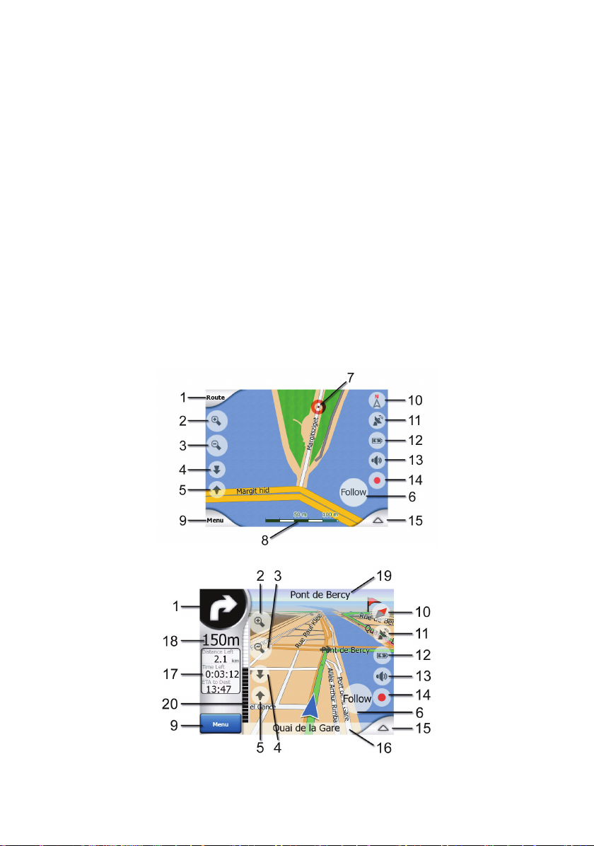
Map screen contents:
67).
67).
Cockpit screen contents:
27
Page 28

No. Display Control
1 (Cockpit only) Turn preview* Opens Route menu*
)lanoitpo(nismooZa/n2
)lanoitpo(tuosmooZa/n3
)lanoitpo(nwodstliTa/n4
)lanoitpo(pustliTa/n5
6
7 Selected map point (Cursor) Opens Popup Info and Cursor menu
8 (Map only) Map scale Zooms in/out by dragging
10 Map orientation and Overview
14 Track Log recording or playback Opens Track Logs screen
16 (Cockpit only) Current street Opens Route Information screen
17 (Cockpit only) Travel and Route data** Opens Route Information screen
18 (Cockpit only) Distance to next turn*** n/a
19 (Cockpit only) Next street*** n/a
20 (Cockpit only) Approaching next turn**** n/a
Indicates that Lock to GPS position and
heading is inactive
* On Map screen only when a route is active
** Contents differ when a route is active
*** Appears only when a route is active
**** Appears only when a route is active and the next turn is near
Re-enables Lock-to-Pos ition / Smart
Zoom
)niaM,etuoR,kciuQ,dniF(uneMa/n9
Switches North-up, Track-up an d
Overview
neercsataDSPGsnepOytilauqnoitisopSPG11
sgnittessnepOsutatsyrettaB21
gnitumselbasid/selbanEdetumronodnuoS31
unemrosruCsnepOa/n51
28
Page 29

4.5.1 Turn preview (No. 1)
On the Cockpit screen this field shows a graphic illustration of the next manoeuvre. For
example when you approach a turn, an arrow will show whether it is a slight, normal or sharp
turn. When showing a roundabout, the number of the exit is also given in the picture.
29
Page 30

This field also serves as a button. Tap it to get to the Route menu (Page 47). The Map
screen will show a button called Route here if there is an active route. This also leads to the
Route menu.
30
Page 31

4.5.2 Zoom in and out (No. 2 & 3)
These semi-transparent buttons are only displayed if "Zoom & Tilt" is enabled in the Quick
menu (Page
Zoom will change the scale of the map. Zoom out shows a larger part of the map, while
Zoom in shows a smaller part of the map in more detail.
The automatic Smart Zoom function will do the necessary zooming for you when navigating
(zooms out if the next turn is at a distance to let you see far ahead and zooms in when
approaching a turn to give you a better view of the upcoming manoeuvre). If you manually
change the zoom level, Smart Zoom will no longer scale the map by itself (automatic tilting
and rotating remain s active).
You need to press Enter (Page
control to Smart Zoom. You can also set iGO to do this automatically after a few seconds in
case of the Cockpit screen (Page
You need to tap the Follow button (Page
can also set iGO to do this automatically after a few seconds in case of the Cockpit screen
(Page
4.5.3 Tilt up and down (No. 4 & 5)
These semi-transparent buttons are only displayed if "Zoom & Tilt" is enabled in the Quick
menu (Page
41).
11), or tap the Follow button (Page 31) to return the zoom
69).
31) to return the zoom control to Smart Zoom. You
69).
41).
This function modifies the vertical viewing angle of the map in 3D mode. You can change the
angle in a wide range starting from a top down view (2 D v iew is seamlessly integrated) all
the way to a flat view that lets you see fa r ahead.
The automatic Smart Zoom function will do the necessary tilting for you when navigating
(gives a flat view if the next turn is at a distance to let you see far ahead and raises the angle
when approachin g a turn to give you a better view of the upcoming manoeuvre). If you
manually change the view angle, Smart Zoom will no longer tilt the map by itself (automatic
zooming and rotating remains active).
You need to tap the Follow button (Page
can also set iGO to do this automatically after a few seconds (Page
4.5.4 Follow mode - lock to GPS position and heading (No. 6)
This semi-trans parent icon is displ ayed if GPS position is available, and the map has been
moved. It also appears when you scale or tilt the m ap while Smart Zoom is enabled.
This semi-trans parent icon is displ ayed if GPS position is available, and the map has been
moved or rotated. It also app ears when you scale or tilt the map while Smart Zoom is
enabled.
31) to return the tilt control to Smart Zoom. You
69).
31
Page 32

Normally iGO positions the map to keep the GPS position visib le somewhere on the map
(when North-up orientation is selected), or always at the bottom centre of the map (when
Track-up orientation is selected).
If you manually move the map, it will freeze the map in the new position. To return to the
GPS position, use this Follow button.
When Smart Zoom is enabled, scaling or tilting the map also stops the automatic zooming or
automatic tilting respectively. To reactivate Smart Zoom, tap t his button.
This button has a hardware button equivalent: Page
Tip: In Advanced settings you can set a delay time after which iGO pushes the Follow button
for you on the Cockpit screen automatically (Page 69). This can be turned on for re-enablin g
both Lock-to-Position and Smart Zoom.
4.5.5 Cursor (No. 7)
As described earlier (Page
Find, it will become the selected poi nt on the map, marked with a small red dot and radiating
red circles to make it conspicuous. You can use this point as starting point, via point or
destination for your route, you can search for a POI near it, mark it with a pin, or save it as a
POI.
Note: When GPS pos ition is available, the Follow button will appear indicating that you ha v e
disabled Lock-to-Position. Tapping the Follow button will re-enable the position lock and
move the c ursor back to the current GPS position. The same happens when iGO restores
Lock-to-Position automatically on the Cockpit screen, if it is set in Advanced settings (Page
20), if you tap the map somewhere or select one specific item in
11.
69).
4.5.6 Map scale (No. 8)
The scale indicator is only available on the Map screen. In 2D map view it represents the
scale of the map. In 3D view it is the scale of the nearest part of the map only.
You can use it in both 2D and 3D modes to scale the map. Drag and pull it right to z oom in,
or left to zoom out.
4.5.7 Menu (No. 9)
This button opens the Menu with the Find engine, the Quick menu, the Route menu and the
exit butt on that takes you to the Main menu screen. The Menu will be described in detail
later: Page
4.5.8 Map orientation and Overview (No. 10)
You can view the map screens in three different presentation modes. This switch will cycle
through them in the following order.
The usual map orientation for navigation is Track-up. It means iGO rotates the m ap during
navigation to always face the direction of your travel. In this mode an arrow (compass) points
towards North.
40.
32
Page 33

Tap this icon to switch to North-up mode. Now the map is fixed to keep facin g North. The
icon changes to show the new rotation mode.
Tap the icon again to enter Overview mode. This mode looks similar to the North-up mode
with one difference: the zoom level in this mode has a fixed default to give you a better look
of where you are on the map. You can change the zoom level at any time, this will not cause
the Follow button to appear, but when entering Overview mode later, the default zoom level
will be restored.
The arrow representing your position will be fixed in the middle of the screen. When you
move the map in Overview mode, the Follow button will appear, and when pushed, it will
move the map to have your current position in the middle of the map again.
You cannot rotate the map in Overview mode. This mode is strictly north-up.
You can set up iGO so that it will switch to Overview mode during navigation when the next
turn is far away. You can specify this distance and the fixed zoom level of Overview in
Advanced settings (Page
An aeroplane icon indicates Overview mode.
Tap the icon again to return to Track-up (automatic rotation) mode.
4.5.9 GPS position quality (No. 11)
Similarly to the icon found on the GPS Data screen (Page
you about the GPS signal:
69).
26), the map screens also inform
• The black satellite dish with the red exclamation mark shows there is no
connection with the GPS receiver. GPS navigation is not possible. Devic es with a built-in
GPS receiver are permanently connected, so this icon may not appear under normal
circumstances.
• Red shows there is a connec tion, but the signal is too weak to give a position.
GPS navigation is not possible.
• Black shows there is a GPS position, and navigation is possible. When only one
arc is shown, the position is 2D (no altitude available), and position error may be
significant, yet iGO is ready to navigate.
33
Page 34

• A black dish and two arcs represent a 3D GPS position. iGO is ready to
navigate.
• When small car symbols are displayed under the dish, TMC information is
available.
4.5.10 Battery status (No. 12)
The status of the battery is also shown by iGO. You can estimate the available power
reserve from the length of the bar inside. Some examples:
• The thunderbolt in the batt ery shows t he battery is being charged.
• Battery is not charging, but it is at full capacity .
• Battery in not full, but there is sufficient reserve capacity.
• When the inside of the battery turns red, the battery needs recharging.
4.5.11 Sound muting (No. 13)
By tapping this button you can quickly mute all sounds of the PNA. This will not modify the
volume level and the enabled or disabled status of the voice guidance or the key sounds (all
to be set on the Sound Settings screen: Page
muting is enabled, the speaker icon is crossed out.
62), just mutes the sound output. When
Tap again to re-enable sounds.
Note: Sound can be muted in S ound settings (Page 62), too. There you have a Master
switch that works together with the switch described above. There is also a Master slider on
that screen. That you can use to fully turn down the volume of the device. Setting the volume
low is different from muting, therefore it will not show up on the mute indicator.
4.5.12 Track Log recording/playback indicator (No. 14)
When a track log is being recorded, a red icon is displayed on the map screens. This icon
also functions as a button leading to the Track Log screen (Page
recording or make the track log visible on th e map.
45) where you can stop the
34
Page 35

During track log playback a green icon will blink. Tapping this icon (in fact, tapping the
screen anywhere) stops the simulation.
4.5.13 Cursor menu (No. 15)
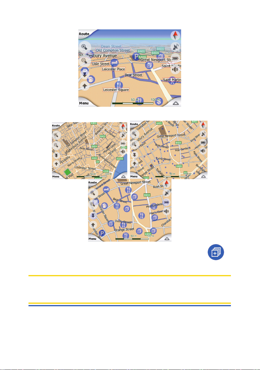
The Cursor is the selected point on the map (marked by a red dot and radiating red circles
around it), or the current GPS position when it is available and Lock -t o-Position is en abled.
When you tap the screen to place the Cursor, the Cursor menu pops up automatically to give
you the list of possible functio ns you can use the Cursor for. At the same time Popup Info
(street name, house number and the list of POIs nearby) appears near the selected map
point if Popup Info is enabled in the Quick menu (Page
If you do not use the Cursor menu in a few seconds, it will automatically vanish back to the
bottom of the screen, and Popup Info disappears, too. You can have them reappear by
reopening the Cursor menu using the arrow in the bottom right corner. When you open the
menu manually, it will stay on until you close it or switch to another screen.
Tip: If you want to see the map around the Cursor, close the Cursor menu and reopen it.
When this menu is opened manually, the map is always moved to have the cursor in the
centre.
40).
The content of the Cursor menu depends on the screen (Map or Cockpit) and it is slightly
different if there is an active route already planned. You have the following op tions:
• Start: use the Cursor as the departure point for your route. This menu point is available
only in Map mode and when there is no active route. In Cockpit mode the departure point
of the route is always the GPS position or if it is not available, the last known GPS
position.
• Route To: use the Cursor as the destination of your route. This button is to start a new
route. The previous route (if it exists) will be deleted and replaced. If a multi-point route is
active, iGO will ask you whether you really want to delete it together with all its via points.
• Add Via: by in serting the selected map point as a via, you instruct iGO to cross this
location before the destination of the route. This is the way to build a multi-point route in
reverse order (wh en you wish to insert a stopover ‘go to A but first get some fuel at B’ or
want to influence the direct ion of the route). This menu point works only if a route is
already active.
35
Page 36

• Remove Via: removes the ‘via point’ near or at the Cursor. The route will be recalculated
immediately excluding the deleted point. This menu point replaces Add Via and is
available only if the Cursor is near or at a via point.
• Continue: add a new destination to be reached after the previous destination. The new
destination replaces the old one, which is now demoted to a via point. This is the way to
build your multi-point route in straight order (w hen you wish to visit several destinations
‘go to A then to B’). This menu point is available only if a route is already active.
• Pin: push a coloured pin in the map at the selected point for later use. This pin is visible
at all zoom levels and also appears in the History list together with its exact position. The
colour of the pin is automatically selected by iGO.
• Unpin: remove the pin near or at the Cursor. This menu point replaces Pin and is
available only if the selected point is near or at a pin.
• POI: opens the list of POIs near the selected point. These are the POIs shown in the
Popup Info window. This menu point is only available on the Map screen. If you want to
add a new POI at the cur sor, you can do so by tapping Add POI in the bottom left corner.
You can also add a new road safet y camera if you tap Add Cam, and set the parameters
(type, direction, and speed). If a camera already exists near the cursor, this button is
inactive, and you can change the parameters of the camera by tapping it in the list.
4.5.14 Current street (No. 16)
This field of the Cockpit screen shows the name or number (as available) of the current
street or road you are driving on.
Tip: Some roads have an alternative name (or number). This is normally shown together with
the primary name in this field. You can hide these alternative names in Map settings (Page
62).
4.5.15 Travel and Route data (No. 17)
The contents of these three fields are different when cruising (without an active route) or
navigating (following an active route).
While cruising, the fields show the present speed, the current speed limit and the time of
day.
While navigating a route, these fields show the estimat ed time needed to reach the
destination (ETE), the distance to destination, and the estimated arrival time at the
destination (ETA) by default.
You can choose what to display in these three fields during navigation, by going to
Advanced settings / Display Options (Page
only restriction is that you cannot select a value that already appears in another field. The
possible field contents are:
68). See the following list for your options. The
• Distance to destination (default value for the left field)
• Time to destination (estimated time en route, default value for the middle field)
• Distance to next via point
• Time to next via point
• Time to next manoeuvre (next route event)
• Spee d
• Spee d limit
• Arrival at next via point
• Arrival at destination (default value for the right field)
36
Page 37

4.5.16 Distance to next turn (No. 18)
This field shows the distance to go before reaching the next route event (turn, roundabout,
exit, etc.)
This field is only displayed when navigating a route.
4.5.17 Next street / Next settlement (No. 19)
This field shows the road or street that comes next in the route itinerary.
If you are not yet in the settlement where this next street is, iGO will display the name of the
settlement instead of the name of the road or street. A bullet symbol will appear next to the
name of settlements to help you tell them apart from street names.
This field is only displayed when navigating a route.
4.5.18 Approaching next turn (No. 20)
This bar is only visible when approaching the next route event. It appears on the screen to
visualise the distance when you get closer than 300 meters (1000 feet) to the next turn, and
it remains visible till you reach the turn.
This field is displayed only when navigating a route.
4.6 Route Information screen
The Route Information screen has all the data and some of the functions you need while you
navigate. Some additional functions can be found in the Route menu (Page
active route one of the buttons is inactive and route data cannot be displayed.
As a reminder, you can open this screen two ways: tapping the Info button in the Route
menu (Page
51), or tapping one of the Route Data fields on the Cockpit screen.
47). Without an
4.6.1 Route data displayed (for destination and via points)
In the top section of the screen you see information about the current route. These fields are
continuously updated while you keep this screen open.
37
Page 38

When you open the screen, all fields contain info rmation on reaching your final destination.
Tap any of the fields to see data on the via points starting from the first one through the final
destination again.
4.6.1.1 Route line
The upper part of this screen shows your planned route as a horizontal line. Its leftmost point
is the start of the route, the rightmost one is the final destination, and you can see your via
point flags along the line, spaced in proportion to their distance.
The blue (yellow when using night colours) arrow representing your position will travel from
the left to the right, giving you visual feedback of your journey.
When you reach a via point, it becomes the starting point of the route, the past will be
deleted, the line with all the other via points will be modified instantly, and the arrow jumps
back to the left.
When iGO needs to recalculate the route, the arrow will not jump back to the left as when
reaching a via point, but it may drift a bit as t he length of the new route may be different from
the previous one.
When the data corresponding to the entire route is displayed in the fields below, the line is
coloured the same way as the route line shown on the map. When you see data that belongs
to a via point, the route is coloured only up to that via point. The rest of the line remains grey.
4.6.1.2 Di stance Left
This value c an also be displayed in one of the Route data fields on the Cockpit screen as
‘Distance to destination’. This is the distance you nee d to travel on the route before reaching
your final destination.
If via points exist, tap and tap again any of the fields to see the d istance to reach the first,
second, etc. via point.
4.6.1.3 Method
This field shows how the route was calculated. It either dis plays the ‘Route’ or the ‘Vehicle’
field from the Route parameter settings. If you have chosen Car, Taxi, Bus or Lorry, the type
38
Page 39

of the route (Fast, Short or Economical) will be displayed here; if you have selected
Emergency, Bicycle or Pedestrian, this information will be displayed here.
4.6.1.4 Time Left
This is an estimated value that can also be displayed in one of the Route data fields on the
Cockpit screen as ‘Time to destination’. It shows the time needed to reach the final
destination of the route based on information available for the remaining segments of the
route. The calculation cannot take into account traffic jams and other possible delays.
If via points exist, tap a n d tap again any of the fields to see the time needed t o reach the
first, second, etc. via point.
4.6.1.5 Estimated Arrival
This is an estimated value that can also be displayed in one of the Route data fields on the
Cockpit screen as ‘ETA to destination’. It shows the estimated arrival time at the final
destination of the route based on information available for the remaining segments of the
route. The calculation cannot take into account traffic jams and other possible delays.
If via points exist, tap and tap again any of the fields to see the estimated arrival at the first,
second, etc. via point.
4.6.1.6 Destination / Via point
This field shows the exact address (or its coordinates if the address is not available) of the
final destination.
If via points exist, tap and tap again any of the fields to see the add ress or coordinates of the
first, second, etc. via point.
4.6.2 Warning icons
The following 5 squares are normally grey. Some of them turn red and show a graphical
symbol in case warning(s) are attached to the planned route. These are warnings, so icons
always show information for the whole route, even if the data fields display values from your
current position to a via point only.
Click on any of the icons to show its description.
A few samples of the available icons:
• This icon shows that you need to pay toll on the recommended route.
• This icon shows that the rout e contains motorways. Tap the icon to see the total
length of the motorways in the recommended route.
• This icon shows that toll motorways are included in the recommended route.
• This icon shows that you need to board a ferry along the recommended route.
• This icon shows that you need to pay for the ferry.
• This icon is displayed when iGO could not plan a route with all your road type
preferences respected. Sometimes it is impossible to find a suitable route near the start or
the destination.
39
Page 40

• This icon warns you that iGO had to recommend a route that does not matc h all
your preferences given at the Route Parameters settings.
• The recommended route contains areas only accessible to pedestrians.
• The recommended route contains unpaved roads.
• The recommended route contains roads that require a permit or permission to
enter.
• Information – any other piece of relevant but not categorised information. Tap the
icon to see the content.
• Next page – displayed w h en more than 5 warnings apply for the recommended
route.
4.6.3 Fit to screen
Tap this button to display an overview of the whole recommended route. You will jump to the
Map screen with a 2D North-up view so that you can check where the route takes you.
4.6.4 Parameters
This butt on opens the Route parameter settings screen (Page
the Route menu (Page
4.7 Menu
Tapping this button brings up a menu that allows you to access some of the most frequently
used functions of iGO.
4.7.1 Find tab
The first page of the Menu is Find. It lets you select a destination without first having to
locate it on the map. The Find menu will be described in detail later here: Page
47).
63) otherwise open ed from
73.
4.7.2 Quick tab
This provides quick access to some configurable options.
40
Page 41

4.7.2.1 3D Map (switch)
When the ligh t is on, the map shows a perspective view. You can use hardware buttons 1
and 2 to change the angle of the view. When the green light is off, the map is displayed in a
conventional top-down view. This 2D view is also the end of the tilt range, so it can also be
accessed by tilting the map up. Conversely, 3D mode can be switched on by tilting down in
2D mode. Map view modes are described here: Page 16.
Note: When you re ach 2D view by tilting the map, Smart Zoom will tilt the map as you press
the Follow button or it disappears after the timeout (set in Advanced settings) expires. Use
the 3D Map toggle to permanently switch to 2D view.
Note: If the map is z oomed out so that the view angle is automatically raised to a top down
view, this button will have no immediate effect. When you zoom back in, the view angle will
or will not change according to the new state of the button.
4.7.2.2 Zoom & Tilt (switch)
When the light is on, additional transparent buttons (Page
map screens for zooming and tilting without the use of hardware buttons.
The Tilt buttons appear only at higher zoom levels. If you zoom out, they disappear.
31) appear on the left side of the
4.7.2.3 Night Mode (switch)
Turn on or off the night colours manually to override the automatic colour scheme switching.
41
Page 42

Note: Using this option turns off the Automatic Night Colours feature. You need to re-enable
it at the General settings screen (Page 57) to have the colours change automatically again.
4.7.2.4 Manage POI (Points of Interest)
Here you can set all the parameters of POIs that you have created and the visibility of t he
built-in POIs that come with the map.
Manage built-in POI visibility
The maps in iGO come with a huge number of POIs. Displaying all of them wou ld make the
maps too crowded (to see how POI items are shown on the map see Page
avoid that, you can decide which POI groups to show and which ones to hide on the map.
iGO has a multi-level POI category system. You ca n set the visibility of the top two levels. All
levels below that will be shown or hidden according to their respective category (i.e. you can
set the visibility of Petrol Stations in the Services category, but all brands listed under that
will either be shown or suppressed together).
Groups shown with a tick mark are visible on the map; groups without a tick mark are
hidden, while the ones shown with a pal e tick mark have some of their subcategories shown
and some others hidden.
If you highlight any of the POI groups, the button in the bottom left corner will become Show
if the POI group is hidden, or Hide if the group is shown or partly shown.
Tip: To make a partly shown group fully shown, tap this button twice. First you will hide the
whole group, and then you will have it displayed with all its subgroups.
Tapping again the highlighted POI group (except for My POI – described later) opens the list
of subcategories of that group. Here you cannot see partly shown subgroups, as visibility
can only be s e t for the top two levels of categories. Showing and hiding a subgroup is done
the same way as for the main groups.
21). In order to
42
Page 43

Manage My POI
By highlighting then tapping again the My POI switch on the Manage POI main screen you
can manage the POI groups and items that you have created.
Note: T he group Unnamed only appears if you have previously saved a POI item without
creating a new POI group for it.
Tapping any of the group names will open a list of POIs saved in that group. This list is
similar to the list of POI results in Find. The POIs are ordered bas ed on their distance from
your current position. If GPS position is not available or you have disabled Lock-to-Position
by tapping the map, the POIs will be ordered by their distance from the Cursor.
When the My POI Groups are displayed, you have t he following options:
43
Page 44

• Show/Hide: similarly to built-in POIs, you have the possibility to show or hide all POIs of
the selected category on the map. Groups with a tick mark are displayed; all other groups
are hidden.
• New: you can create a new My POI group by tapping this button. You need to select an
icon, a name, and the maximum zoom level at which the POI is still visible on the map
(provided you let the POI group be displayed at all). You do not necessarily need to
create POI groups in advance. You can do it while saving a new POI.
• Delet e: you can delete any of your previously saved My POI groups. This will delete all
POIs in that group. iGO will ask you to confirm this action.
• Edit: you can edit the attributes (name, icon, visibility level) of a previously created My
POI group.
• Left/right arrows: if your groups fill several pages, these buttons will let you b rowse
through them. The green fiel d left of these buttons sho ws the current page number and
the number of pages.
When the list of My POIs is displayed, you have the following options:
• Search: you can shorten the list of matching POI items by filtering. Just like in Find, enter
a few letters of the desired POI name. When the nu mber of matching items can fit in one
page, iGO will automatically display the list. If you tap Done any time before this happens,
you receive the list of matches on multiple pages.
• ABC/Distance: by tapping this button you can have the POIs sorted in an alphabetical
order. Tapping again will return to the distance-based order.
When you tap on any of your POIs in the list, you will open a new window with the details of
the selected POI.
Here you have the following options:
• OK: if you tap this button, the map screen returns with the selected POI in the middle.
44
Page 45

• Edit: you can edit the attributes (name, icon and group) of the selected POI.
• Delet e: you can delete any of your previously saved POIs. iGO will ask you to confirm this
action.
4.7.2.5 Popup Information (switch)
When this feature is enabled, tapping the screen (activating the Cursor, a radiating red dot)
on either of the map screens also opens a pop-up box with the selected street name, house
number and the name of the nearby POIs, if any.
Tip: Tapping one of the blue Information icons behind the POI names shows the details of
the appropriate POI item.
4.7.2.6 Manage Track Logs
Using iGO it is also possible to save t he track logs of your journeys. This screen lets you
manage all your track logs. When it comes up, it shows a list of all track logs alre ad y saved.
45
Page 46

The original name of a track log is the date and time when it was recorded. You can change
their name to something more meani ngful if you wish.
Each track log has a colour, shown to the left of its name when the track log is visible on the
map. If the track is not visible, a horizontal line is shown here. Tapping the line of the
highlighted track log will toggle between showing and hiding that log. The track log will be
drawn on the map using the colour next to its name.
When a track log is being recorded, a new line appears in this list with a horizontal line, as
newly recorded trac k logs are not shown in the map normally.
Tip: If you wish to see the track log currently being recorded, highlight its line then tap again
to make it visible.
In this screen you have the following options:
46
Page 47

• Record: this will initiate track log recording. A new line appears in the list, and GPS
position data will be saved until you stop the recording or exit iGO. A red ic on (Page
is shown on the map screens to let you know that a recording is in progress. Tapping that
icon opens this Track Log screen.
34)
• Stop recording: if recording is in progress, this buttons stops it.
• Info: this button opens a screen that shows the track log details, and lets you:
• change the name of the track log (Rename button),
• change the colour of the track log (Colour on the map selector),
• have it displayed on the map (Fit to screen button),
• Replay: push this button to see a simulation of the saved trac k log on the map. A green
icon (Page
34) will appear on the ma p screens to let y ou know it is a simulation only.
• Delet e: you can delete a track log if it is not needed any more. iGO will ask you to confirm
this action.
4.7.3 Route tab
This menu contains options to manage different settings in the program.
4.7.3.1 Recalculate
This menu point is only available if an active route exists and GPS position is present.
It brings up a menu with four options. Using one of these functions you can modify the
current route.
47
Page 48

Recalculate
This function repeats the route calculation based on the same settings as used to calculate
previously. This possibility is typically used w he n automatic off-route recalculation is
disabled. However you may consider using it when you travel on a road parallel to that
recommended by the route. In this case iGO may not recalculate the route for some time ,
but y ou can force recalculation here. This is also the button you will most frequently us e
when the window appears automatically, provided that the manual route recalculation is set
61).
(Page
Drop Next Via Point / Delete Route
You can modify the route to skip the next v ia point if you decide it is no longer needed. For
example, you may have added the via point only to influence the route but you do not want
to actually reach it; or you have already almost reached it, and iGO still keeps on navigating
towards that point. When there are no via points left (only the destination), the name of this
button turns to Delete Route, and it cancels the navigation.
Bypass
When you run into a traffic jam or roadblock, you may want to hav e iGO calculate a route
that departs the original route as soon as it can. You will need to select the minimum
distance along the original route where your new route is allowed to rejoin the original route.
Select the one you feel appropriate for the traffic difficulty you face.
Note: This function is to give you an alternative for the next section of the recommended
route. To change later parts of the route or to avoid specific streets or turns, use the Avoid
function in Itinerary instead (Page
Note: When you use this feature, iGO will keep on excluding the same part of the map from
later routes until you manually delete the route (Page
49).
49), or restart iGO.
48
Page 49

Cancel
This option returns directly to the map screen without recalculating the active route. If you
choose this optio n when manual route recalculation is configured (Page
stops and will be activated again when you are back on your original route.
4.7.3.2 Delete
Tap Delete to erase the active route along with all its route points (start, via points and
destination). If you later decide that you need the same route again, you will have to rebuild
it from scratch. iGO will warn you before deleting route data.
This function has a special role if you have used the Avoid feature during your journey.
When y o u arrive at your destination, the route line disappears on the map and navigation
stops. The route is now practically delet ed, but if you plan a new route, the roads,
manoeuvres and are as excluded from your route will also be avoided when planning the new
route. Tap Delete to completely delete your previous route together with its Avoid
restrictions.
Note: When a POI item is used as a route waypoint, deleting the route will not delete the POI
item itself, just its role in the route.
4.7.3.3 Itinerary
This function opens the itinerary (route event list) of the active route. The Itinerary has thre e
different display modes and two functions.
Display modes
Display modes are different only in the number of events displayed in the list. List items are
always shown with all information available including pictograms of the needed action and
distance of the event from the previous list item.
The Itinerary is live and constantly updated when navigating a route. The list item coming
next in navigation is the highlighted one until you highlight another on e by tapping. After that,
the highlight remains on the item you have selected.
61), navigation
• Detailed Instructions: this is the list displayed when Itinerary is opened. It is the list of
events in full detail. All signific ant junctions are shown in the list, even ones to be passed.
• Instructions: by tapping the Mode button once you will see the list of events that need
your attention, i.e. the list of manoeuvres during the route. These are the events shown in
the Turn preview field and announced by the voice instructions.
• Route summary: tapping the Mode button again will show an overview of the route that
contains only the significant roads and intersections.
Show
49
Page 50

Tap this button to see the highlighted list item on the m ap. This will help you identify route
events in the list.
Avoid
Tap this button to show a list of possibilities for modifying the route. They let you recalculate
the route avoiding the highlighted event and sometimes also some of the subsequent ones.
• Man oeuvre: this option avoids the highlighted action. For example if you find a turn too
difficult during rush hour traffic, iGO will recalc ula te the route excluding that turn. If the
next street is important in the route, it is likely that iGO will replace the turn with several
easier ones to get to the same street.
• Road: when you exclu de a road, iGO will calculate a route that does not use that road. It
is useful when you anticipate a traffic jam in a street used in your route, or a roadblock is
announced on the radio, and you find that road in your Itinerary.
• Distances: you can also find some distance buttons in this list. They are similar to the
ones in the Bypass list of the Recalculate menu (Page
distant parts of the route.
Note: You need not open Itinerary if you run into a roadblock or traffic jam. To get an
immediate alternative route use the Bypass function of Rec al culate (Page 47).
Note: When you use this feature, iGO will keep on excluding the same part of the map from
later routes until you manually delete the route (Page
4.7.3.4 Fly Over
This feature has no nav igation function , it merely provides a quick view of the route. It will
present a simulation of the route showing what you will see later when navigating.
Lifelike simulation
Tap the Fly Over button.
In this mode the simulation is run at normal speed (using the speed limit of the streets and
roads in the route), and voice instructions are also played.
This mode is mainly useful for demonstrating iGO, or to learn the way it works before you
start your first journey.
Tap anywhere on the screen to stop the simulation.
4.7.3.5 Edit
Tap Edit to see the list of all points used in the route. The first item in the list is the departure
point of the ro ute without a valid GPS position, the last reached via point if you open the list
during navigation, or the point where iGO most recently recalculated the route. This means
the list is permanently updated, and via points drop out during the journey. The last item in
the list is your final destinat ion.
47), but these can also be used for
49), or restart iGO.
50
Page 51

Use the arrows on the right to browse through th e list and tap any line to highlig ht it. You can
perform the following operations:
• Add: you can add a new route point (or a new final destination if the
highlighted item is the last one in the list) after the selected point. The Find menu opens
automatically to let you search for an address, POI, coordinates, one of your favourite
destinations, or select a point from the History list. As soon as you select any of these,
iGO returns to the Edit screen and your selection appears right under the highlighted line.
• Delete: you can delete the selected point from the list. If the highlighted item is
the last one in the list, the previous via point will be promoted to be the final destination.
• Optimise: you can optimise the order in which you will drive through the via
points, if there is no specific order you would like to keep. When tapping this button, iGO
reorders the list instantly to save you time and fuel. Optimisation is for via points only.
Your starting point and destination remain in their positions, of course.
• U p and Down: using these buttons you can reorder the list by moving
the highlighted item up or down in the list.
4.7.3.6 Info
This button opens the Route Information screen described here: Page
shows information about the current route and has a few additional options to check and
modify your active route.
37. This screen
51
Page 52

4.7.4 Main button
The Main button at the bottom right corner leads to the Main menu screen described here:
Page
15.
4.8 TMC (Traffic Message Channel)
iGO can provide you with even better routes if Traffic Message Channel ( TMC) information is
available. The TMC is a specific application of the FM Radio Data System (RDS) used for
broadcasting real-time traffic and weather information.
Note: TMC is not a global service. It may not be available in your country or region. Ask your
local dealer for coverage details.
You need a TMC receiver attached to your PNA to receive TMC information.
If public TMC dat a is broadcast at your location, iGO will automatically take into account the
TMC information received. You do not need to set anything in the prog ram. The receiver will
automatically search the FM r adio stations for TMC data, and the decoded information will
immediately be used in route planning. The moment iGO receives traffic information that
may affect your route, the program will warn you that it is recalculating the route, and
navigation will continue with a new route that is optimal considering the most up-to-date
traffic conditions.
The TMC subsystem can be started from the GPS Data screen (Page 25) by tapping the
TMC button.
4.8.1 List of TMC messages
The main screen of the TMC section is the list of valid TMC messages ordered by their
distance from your current location.
Tap the arrows to turn the page, and see traffic difficulties farther away from your current
position, or press Settings to configure the TMC subsyst em. This opens a new window.
4.8.2 TMC control centre
This screen shows the selected TMC source and allows you to change the TMC settings.
52
Page 53

4.8.2.1 Selected FM radio station
The name and frequency of the selected radio station will appear at the top of this window,
together with signal strength information indicated by a bar simila r to the GPS satellite signal
strength bars on the GPS Data screen.
If there are no radio stations broadcasting TMC data in your area, the receiver keeps on
searching. You will see the frequency continuously sweeping across the FM CCIR radio
band (87.5-108 MHz). When you move to an area with TMC information, the indicator will
show the frequency, and detailed information for the TMC station.
4.8.2.2 Exclude selected station
If you wish to receive TMC data from a different radio station, push this button. The radio
station will be added to the list of excluded stations, iGO will start searching for another TMC
station, and will always skip the excluded station in the future.
4.8.2.3 Show excluded stations
This button opens the list of excluded radio stations. Tap any of the stations in the list, then
tap Enable to allow iGO to accept TMC information from this station.
4.8.2.4 Sort events by distance / type
The list of traffic events can be ordered by their distance from the current position, or by their
type. Tap this button to toggle between the two possibilities.
4.8.2.5 Use traffic information
This button is enabled by default, which means that TMC messages are used in route
planning. Tap this button to have iGO ignore real-time traffic information when planning
routes.
Tip: If you make a route planning for a future journey, it may b e better to turn off TMC
corrected route planning.
4.8.2.6 Recalculate to avoid traffic
This setting is similar to the previous one. Disabling it will not prevent the system from using
TMC data for route planning, but will not trigger an automatic recalculation when the traffic
conditions change during your journey.
53
Page 54

4.9 Road safety cameras
Road safety cameras, such as speed cameras and red light cameras are special POI types
in iGO. Th e application can warn you when you approach one of these cameras. You can
fine-tune this warning in General settings (Pa ge
You can save camera locations manually. It is described in detail at the Cursor menu (Page
57).
35).
Speed cameras are displayed with small camera symbols on the map.
4.9.1 Camera types
There are four types of speed cameras:
4.9.1.1 Fixed cameras
Some cameras stand by the roadside, looking in one direction, measuring one or both
directions of the traffic. They measure your current s peed. For these cameras you can
specify the controlled traffic direction and the speed limit. iGO wi ll warn you when you
approach these cameras in the measured direction. If your speed exceeds the speed limit
near the camera, a special warning sound will be played.
These cameras are displayed with the following s ymbol:
4.9.1.2 Mobile cameras
Some cameras are operated from vehicles. The database contains some typical places of
these mobile cameras. They are not always operational at the given location, and the speed
limit is not specified for them. The warning is similar to fixed cameras, but as there is no
speed limit given, only the proximity is announced.
These cameras are displayed with the following s ymbol:
54
Page 55

4.9.1.3 Built-in cameras
Some cameras are built in traffic lights. They work like fixed cameras, but they are difficult to
spot. The warning for proximity and speeding is the same as for the fixed cameras.
These cameras are displayed with the following s ymbol:
4.9.1.4 Section control cameras
These cameras work in pairs, and do not measure your current speed but your average
speed between the two cameras. Both will identify your c ar , and record the exact time you
pass them. The difference between the two points of time will be used to calculate your
average speed.
iGO will warn you when you approach one of these cameras, but as you pass by, the
warning stays on, and your av erage speed is measured until yo u reach another camera of
this type. If your average speed exceeds the speed limit between the two came ras, you will
receive the same special w arning sound as with the other camera types.
Note: In the rare case iGO cannot register the moment you pass the second camera (e.g. it
is placed at the exit of a tunnel where GPS position is not yet available) the warning will
continue. Just tap the came ra symbol displayed on the screen to stop the warning.
These cameras are displayed with the following s ymbol:
4.9.1.5 Red light cameras
These cameras check if you obey traffic lights or not. The warning is similar to fixed
cameras, but as there is no speed limit given, only the proximity is announced.
These cameras are displayed with the following s ymbol:
4.9.2 Controlled traffic direction
The different cameras can measure the speed of one direction of the traffic, both directions,
or even several directions in an intersection, when they are mounted on a rotating base. iG O
warns you only if you drive in a measured or possibly measured direction.
The measured direction of the cameras is displayed with the following symbols:
55
Page 56

4.9.3 Speed limit checked
As additional information, the speed limit checked by the camera is given for fixed, built-in
and section control cameras . When you manually save a camera location from the Cursor
menu (Page
change this value with the given control:
4.9.4 Add a new camera or edit an existing one
You can add new cameras, modify the parameters of existing ones, or delete them. Select a
point on the map, then use the POI button in the Cursor menu (Page
list of POIs around the selected map point. To add a new camera, use the Add Cam button,
and set its parameters. To edit an existing camera, find it at the end of the POI list, and tap
it. A new screen will open with its details. Tap Delete on this screen if you wish to cancel th e
camera.
4.9.5 Change the settings of the camera warni ng
You can t urn on and off the camera w arning, and fine-tune its settings in General settings
(Page
35), the speed limit of the road (if available) is used by default, but you can
35). This will open the
58).
56
Page 57

5 Settings
iGO provides several settings in order to let you customise the functions of the program. The
Settings screen can be accessed directly from the Main menu screen (Page
the map screens by using the battery icon (Page
accessible from other parts of the program.
5.1 General settings
These are the basic settings of iGO.
34), while some of its sub-screens are
15) and fro m
5.1.1 Safety Mode
Safety mode will disable the touch screen above 10 km/h (6 mph) to keep your attention on
the road.
You are still able to use the hardware buttons, but you cannot set a new destination or
change the settings.
When you disable Safety Mode, iGO will warn you.
5.1.2 Set Favourite Destinations
You can select two of your most frequent destinations to be your favourites (Page
can start navigating to either of them by only two taps on the screen. The original names of
these points are Home and Work.
83). You
57
Page 58

You can rename them and specify their locations. To determine the location you can use the
same Find menu options (Page
and the information available, the location will be shown here as a street address, a
latitude/longitude position, or both.
Note: If you tap either of your favo uri te destinations in the Find menu (Page 83) before
defining it, iGO will offer to take you to this screen to set it up.
5.1.3 Automatic Night Colours
Using the automatic night mode, iGO will change between the daylight and night colour
schemes a few minutes before sunrise and a few minutes after sunset based on the time
and location information provided by your GPS. Once you set a permanent colour scheme in
the Quick menu (Page
colours for you again, you need to re-enable this feature.
5.1.4 Alerts
Tap this button to enable and fine-tune user alerts. A new window opens with the options.
41), this automatic mode turns off. If you need iGO to switch between
73) as for a route destination, and depending on that choice
58
Page 59

5.1.4.1 Warn When Speeding
Maps may contain information about the speed limits of the road segments. iGO is able to
warn you if you exceed the current limit. This information may not be available for your
region (ask your local dealer) or may not be fully correct for all roads in the map. This setting
lets you decide whether you want to receive the warnings or not.
Speeding tolerance
iGO will warn you when you exceed the speed limit by the amount specified here. Select
whether you want to specify the tolerance as a Fixed value (offset to the speed limit) or as a
Percentage.
The slider will change depending on which mode you have chosen.
Both positive and negative values can be given in either offset or percentage mode.
Alternative speed li mit
If the speed limit of the current road segment equals or is above this limit, the speed warning
will use the alternative tolerance instead of the previous one.
Move the slider to its rightmost position to turn off the alternative speed warning. Then the
settings of the upper slider will determine the warning for all roads.
Alternative speeding tolerance
If the speed limit of the current road reaches the value set at Alternative speed limit, this
setting will replace the basic one set at the top of this screen. The slider and the selector
work exactly as the basic ones desc ribed here: Page
Example: to let you better understand how this feature works, here is an example. If you use
the settings +10 km/h – 100 km/h – +5%, iGO will warn you when driving at the following
speeds:
59.
59
Page 60

Speed limit Warning at
40 km/h 50 km/h (=40 km/h + 10 k m/h)
60 km/h 70 km/h (=60 km/h + 10 k m/h)
90 km/h 100 km/h (=90 km/h + 10 km/h)
100 km/h 105 km/h (=100 km/h + 5%)
120 km/h 126 km/h (=120 km/h + 5%)
160 km/h 168 km/h (=160 km/h + 5%)
5.1.4.2 Enable Safety Cameras
iGO can warn you when you approach known speed and red light cameras previously
uploaded or copied into the device, or saved manually in the soft ware. You can save
cameras using the POI button in the Cursor menu (Page
The types and parameters of speed cameras are explained here: Page
35), and then the Add Cam button.
54.
In this section you can enable or disable the warnin g for known cameras, and you can also
fine-tune the way iGO warns you when you approach one of these cameras.
Note: Detecting the location of speed cameras may be prohibited by law in certain countries
or regions. Be sure to check if it is legal to turn on this warning or not before doing so.
Audible Warning
You can disable the audible warning; have a simple warning (when you are warned only if
you exceed the speed limit when approaching a camer a); or a complex sound with repeated
beeps as you approach the camera. In case of section control cameras, you will also hear
these beeps while you are between the two cameras (these cameras work in pairs).
You are warned well in advance. The distance iGO st arts warning you before reachi n g the
camera depends on your speed. The higher the speed, the earlier the warning starts.
5.1.5 Route Recalculation
Once a route is planned, t his setting will tell iGO what to do when you deviate from that
route.
5.1.5.1 Automatic
The route will be recalculated automatically a few seconds after you go astray.
60
Page 61

5.1.5.2 Ask First
iGO can also ask your preference each time you leave t he planned route. The route will not
be recalculated until you make your choice from the menu that automatically appears (also
explained here: Page
Your options are:
39).
• Recalculate: iGO will recalculate the route with the previous settings. The result is the
same as if Automatic recalcula tion was selected.
• Drop Next Via Point / Delete Route: iGO will remove the next via point from the list and
recalculate the route without it. If you have only one target left, the label of the button will
be Delete Route, and it will end navigation.
• Bypass: if you have deviated from the original route because of a traffic jam or
roadworks, you can instruct iGO to avoid the original route for a specified di stance.
• Cancel: you can exit without recalculating the route. Navigation stops and will be
activated again when you find your way back to the original route.
5.1.5.3 Disabled
If you stick to the original route, and you wish to get back to it on your own, you can disable
recalculation. This way guidance will stop until you return to the recommended route on your
own.
5.2 Map settings
You can set a few parameters det ermining the appearance of the maps in iGO.
5.2.1 Daylight / Night colour profile
iGO com es with different colour schemes for both daylight and night use. There is always
one selected daytime scheme and one selecte d night-time scheme. iGO uses these when
switching from day to night and back.
Tap the appropriate button and select a new scheme from the list.
61
Page 62

5.2.2 Alternative Road Names
Some highways have an international nam e or number for foreign travellers. You can decide
whether to show only the local name or both.
5.2.3 Show Street Labels
You can set whether or not to see the names of the streets and the POI icons on the map
when driving. Based on the current zoom and tilt levels, street names are displayed either
aligned with the street or on signposts stuck into the streets (Page
signs on, it will be easier to recognise your location on the map, if you turn them off, it will be
easier to see the road geometry.
Note: You can only disable street names and POI icons if iGO follows your position. As soo n
as you mov e the map and Lock-to-Position (Page 31) is disabled, street names and icons
become visible again. Tap Follow to re-enable Lock-to-Posit i on and have the labels and
icons disappear a gain.
5.2.4 Textured Polygons
Enable textured polygons, and have rivers, lakes, forests and other large objects displayed
in a more realistic and attra ctive way on the map.
Disabling it will lead to uniform areas but better performance for old PNA devices with a slow
processor. See Page
5.3 Sound settings
Settings on this page deter mine the way iGO sounds.
19.
18). If you switch these
Note: The Mute function (Page 34) accessible from the map screens overrides the settings
on this screen. When iGO is muted, all sounds disappear. These settings will not be
changed; only the output will be muted temporarily.
5.3.1 Master sound volume/switch
The loudness of iGO is independent of your PNA setting s. When you run iGO, the position of
this fader determines the device volume level. When you exit the program, the devic e
settings return.
The left part of this control works as a mute button. Tap to mute all iGO sounds.
This works in tandem with the Mute button (Page
them will change the status of the other.
5.3.2 Voice guidance volume/switch
The switch on the left can turn on or mute iGO's audible guidance. When turned on, the
slider on the right will adjust the loudness of voice prompts. In its leftmost position the voice
guidance is suppressed, in its rightmost position the master volume applies.
34) on the map screens. Switching one of
62
Page 63

5.3.3 Key sound volume/switch
The switch on the left can turn the key s ounds on or off. Key sounds are audible
confirmations of either pressing hardware buttons or tapping the touch screen. When key
sounds are turned on, the slider on the right will adjust their loudness. In its leftmost position
the key sounds are suppressed, in its rightmost position they are played at the master
volume level.
Note: The sound effects of iGO are context sensitive. They will be different if, for example
you open or close a window, or you enable or disable a s etting. They will even let you know
if you have entered enough letters of a street name to have a short list of matching streets
on the screen.
5.3.4 Dynamic Volume
When driving at high speed, the noise in the car may be too loud to clearly understand the
voice guidance messages and to perceive the key sounds. Using Dynamic Volume you can
instruct iGO to increase the volume when your speed exceeds a certain minimum, and reach
its highest volume (determined by the Master volume slider in Sound settings) at the given
maximum speed.
Tap the Dynamic Volume button to turn on the feature. This will also open the screen where
you can set the minimum and maximum speeds.
5.3.5 Attention Tone
If this is set to Disabled, the voice guidance will sound without a preceding attention tone.
Setting it to Single Tone will initiate a single attention tone before the instructions, while
Double Tone will use a double tone.
5.4 Route parameter settings
This is a very important page. Settings here determine how routes will be calculated. This
screen is directly accessible from the Route Information screen (Page
37).
63
Page 64

5.4.1 Method
Use the handle to set the speed of the route c alculation. I n the leftmost position the route
may not be optimal but the calculation will be very fast. Sliding it to the right will result in
more accurate routing in an increased amount of time.
Note: Since iGO calculates routes very quickly, the position of this slide is only used for long
routes. Short routes are always calculated to give you the optimal result independent of the
slider.
5.4.2 Route
Here you can choose from three different route types.
5.4.2.1 Short
Choosing Short will result in a route that has the smallest total distance of all possible routes
between the given points. This is usually preferred by pedestrians, cyclists or slow vehicles.
5.4.2.2 Fast
Choosing Fast will result in the quickest possible route, given that you can trav el at or near
the speed limits on all included roads. This is usually preferred for fast and normal cars.
5.4.2.3 Economical
This setting is a wise combination of the previous two. Although basically going for the
fastest solution, if there is another route taking a bit more time but a lot less distance
compared to the fastest one, iGO will choose this one instead to save fuel.
5.4.3 Vehicle
You can set the type of the vehicle that you will use to navigate the route. Based upon this
setting, some of the road types will be excluded from the route (e.g. motorways for
pedestrians), or some of the restrictions may not be taken into account (e.g. emergency
vehicles have no restrictions).
Furthermore, when Bus or Lorry is chosen, the program assumes that high speeds cannot
be achieved, and this information is taken into account w hen calculating the route, the
estimated time enroute (ETE), and the es timated time of arrival (ETA).
Available values:
• Car
• Taxi
• Bus
• Lorry
• Emergency
• Bicycle
• Pedestrian
64
Page 65

5.4.4 Road types to include/exclude
To let the route fit your needs you can also set which road types are to be considered for or
to be excluded from the route if possible.
Note: Excluding a road type is a preference. It does not necessarily mean total prohibition. If
your destination can only be accessed using some of the excluded road types, iGO will use
them but only as much as necessary. In this case a warning icon will be shown on the Route
Information screen (Page
in alternate colour on the map.
5.4.4.1 Unpaved Roads
Unpaved roads are excluded by default, as they can be in a bad condition and you usually
cannot reach the speed limit on them.
5.4.4.2 Motorways
When driving a slow car or towing another vehicle, you may prefer not to take motorways.
5.4.4.3 Ferries
The accessibility of temporary ferries is not necessarily included in the map data.
Furthermore you may need to pay fare, so you may consider disabling them from t h e preset
enabled status.
5.4.4.4 U-turns
Although displayed amongst road types, this is a type of action. Most drivers prefer to
replace them with a few normal left and/or right turns in the next few junctions, so it is
disabled by default.
Turning back on dual carriageways is not considered as a u-turn.
Note: If you are not totally against u-turns, leave them on here, and add a certain penalty
(equivalent extra distance to travel) in Advanced settings Route options (Page 71).
Note: Via points are handled as stopovers with regards to u-turns. It means disabling u-turns
on this page will avoid u-turns during the entire route if possible, but when reaching a via
point, the following part of the route may be planned starting in the opposite direction.
5.4.4.5 Permit needed
To use some roads or enter some areas you may need special permit or permission from the
owners. These roads are excluded from your routes by default. Use this switch if your
vehicle is authorised to enter.
5.4.4.6 Toll Roads
Toll roads are included in your routes by default. If you wish to travel more to avoid paying a
toll, disabling them will make iGO plan the best toll-free route fo r you.
Note: You have a few more ways to influence routing and route recalculation in Advanced
settings Route options (Page 70).
5.5 Language & Units
Here you can set the languages, measurement units, and date and time formats used by
iGO.
37), and the road not matching your preference will be displayed
65
Page 66

5.5.1 Program language
This button displays the current written language of the program. By tapping the button you
can select from a list of available languages. iGO will have to be restarted if you change this
setting. iGO will ask for confirmation before it restarts.
5.5.2 Voice language
This button shows the current language of the voice guidance. By tapping the button you can
select from a list of available languages and speakers. Tap any of these to hear a sample
voice prompt. Just tap OK when you have selected the new spoken language.
5.5.3 Units
You can s et the distance units to be used by the program. iGO may not support all of the
listed units in some voice guidance languages. If you select a measurement unit that is not
supported by the chosen voice guidance language, you will see a red warning message
under the selector.
5.5.4 Set Date & Time Format
You can set the date and time for mat displayed by iGO. Various international formats are
available.
5.6 Advanced settings
These scre ens let you set a large number of different advanc ed settings and initiate some
special functions. These settings and functions are divided into groups.
66
Page 67

Tap on any button to set the corresponding parameters. They all open new windows where
you can make your desired changes.
5.6.1 Display options
These settings determine how iGO displays different content elements or how it presents the
screens.
5.6.1.1 2D in Map mode (and North-up orientation)
The normal use of the Map mode is to browse the map and look for different places on it. It
is usually done in a top down view having north towards the top of the map. By default iGO
uses the same look for the map in both Map and Cockpit modes.
Use this switch to instruct iGO to always open the Map mode in 2D with North-up orientation
for map browsing purposes.
Note: You will still have the possibility to rotate and tilt the map, but the map will return to 2D
mode whenever Map mode is started.
5.6.1.2 3D in Cockpit mode (and track-up orientation)
The normal use of the Cockpit mode is cruising or navigating, when the road lying in front of
the driver is the most important part of the map. It is usually done in a 3D view with the
current direction towards the top of the map. By default iGO uses the same look of the map
in both Map and Cockpit modes.
Use this switch to instruct iGO to always open the Cockpit mode in 3D with Track-up
orientation (automatic map rotation) for driving purposes.
Note: You will still have the possibility to switch the map to 2D view or north-up orientation,
but the map will return to 3D mode with map rotation whenever Coc kpit mode is started.
5.6.1.3 Zoom in after find
When this s wit ch is turned off, iGO will centre the map to the location selected in Find but
will not change the zoom level. If you turn this switch on, iGO will also zoom in to the
selected point.
The zoom level in this case depends on the type of object you have searched for. For
example in the case of a city search, the zoom level will show you the whole settlement or at
67
Page 68

least a significant part of it around its centre. Selecting a POI, a junction or an exact address
will give you a closer look with only a few streets on the display.
5.6.1.4 Coordinate display format
Positions are sometimes displayed with their addresses, and sometimes with their
coordinates. This setting lets you choose between displaying coordinates in degrees
(dd.dddddd); degrees and minutes (dd mm.mmm); or degrees, minutes and seconds (dd
mm ss.s).
Note: the coordinate display mode is independent from the coordinate input in Find menu.
You can use all three formats freely on the coordinate input screen.
5.6.1.5 Cockpit screen layout
Their content is fixed in Cruise mode (when there is no active route), but for Navigation
mode you can change their content on this screen. The available v alues are listed here:
36.
Page
5.6.2 Backlight settings
Here you can set how the display backlight behaves when using iGO.
These settings are independent of the settings of the other applications of PNA.
5.6.2.1 Power management
At the top of the screen you can set how the backlight will behave when the screen has not
been touched for a while.
Backlight always on
You can choose to have the lights always on.
Smart powersave
You can also initiate this special feature of iGO. When running on battery Smart Powersave
will light up the screen only when you press or tap a button, or if iGO has something to sho w
you. After a few seconds the light level decreases, and after another few seconds the
backlight turns off. This helps you achieve a longer battery life.
5.6.2.2 Br ightness
You can set the backlight level separately for both daylight and night modes, thus enhancing
the effect of the night colour scheme.
The values are between 0 and 10, where zero means there is n o backlight at all, and 10
represents the maximum backlight value.
5.6.3 Smart Zoom
Smart zoom is a lot more than just a usual automatic zoom.
While navigating a route: when approaching a turn, it will zoom in and raise the view angle
to let you easily recognise your manoeuvre at the next junction. If the next turn is at a
distance, it will zoom out and lower the view angle to be flat in order to let you see the road
68
Page 69

in front of you, or it can even switch to an Overview mode to let you follow your position on
the map.
While cruising: if there is no active route and you are just driving, Smart Zoom will zoom in
if you drive slowly and zoom out to the limit set here when you drive at high speed.
These automatic features can be set up on this screen.
5.6.3.1 Smart Zoom settings
You can set how close Smart Zoom can zoom in when approaching the next turn (Zoom-in
limit), and the maximum zoom level to zoom out when the next turn is further away (Zoomout limit). The default values are set to be optimal in most cases.
5.6.3.2 Enable Overview mode
You can configure how the Overview mode is triggered when the next turn is at a distance.
The Route event distance will determine when iGO switches to the Overview or back to the
Navigation view.
The Overview zoom level will determine the fixed zoom level of the map in both automatic
and manually selected (by the Map orientation icon – see here: Page
You can change the zoom level manually at any time (the Follow button will not be
displayed), but when you enter the Overview mode again, the zoom level will be reset to this
value.
You can also move the map in Overview mode. Then the Follow button will appear, and
when pushed, it will move the map to have your current position in the middle again.
Note: when this automat ic feature is disabled, you can still enable the Overview mode
manually as described here: Page 32.
5.6.3.3 Restore Lock-to-Position and Smart Zoom
As described at the hardware buttons and the map screen functions, you can move, rotate,
tilt and zoom the map during navigation. In these cases a Lock icon (Page
the screen.
As already mentioned, you can move, tilt and zoom the map during navigation. In these
cases a Lock icon (Page
When you tilt or zoom the map, that part of Smart Zoom is automatically deactivated, the
map will still follow your position, but will not change the view parameter you have modified.
You can return to the full Smart Zoom mode by tapping the Follow button.
If you move the map, all parts of Smart Zoom become deactivated, and the view freezes.
Tapping the Follow button makes iGO follow your position again (Lock-to-Position) and also
re-enables Smart Zoom.
You can make iGO push the Follow button for you automatically after a fe w seconds of
inactivity.
31) appears on the screen.
32) Overview modes.
31) appears on
69
Page 70

This functionality and the related parameters below apply to the Cockpit screen only. The
Map screen will wait for your action.
Restore Lock-to-Position
Turn this switch on if you want iGO to return to your current GPS position after you have
moved the map during navigation. This is useful if you have moved the map accidentally, or
if you have moved it to quickly check something near your route.
After a certain timeout set below, the Follow but ton disappears, and the map immediately
jumps back to show your current position.
Restore Smart Zoom
Use this switch if you want iGO to re-enable Smart Zoom after zooming or tilting the map
during navigation. This is useful if you have changed the view accidentally, or you modified it
to quickly check something near your route.
After a certain timeout set below, the Follow button disappears, then Smart Zoom changes
the view back for navigation. Unlike with Restore Lock-to-Position, the view changes
smoothly.
Note: Smart Zoom can only be re-enabled when it is activated at the top of this page. With
Smart Zoom turned off, neither does the Follow button appear, nor will the view return to its
previous state if you zoom or tilt the map.
Delay before restoring
You can set the timeout for both Rest ore Lock-to-Pos i tion and Restore Smart Zoom here.
Shorter delays are b est if you tend to accidentally change the map display, but you may
prefer a longer delay if you often look for things around your position while driving.
Remember to only look at the display if it is absolutely safe to do so.
Note: If you push the Follow button before the automatic Lock comes into effect, Smart
Zoom and Lock-to-Position will be re-enabled instantly.
5.6.4 Route options
You can set the basic route parameters on the Route Parameters settings screen described
in Page
63. On this screen you have some more way s to influence route planning and route
recalculation.
5.6.4.1 Off-r oute sensitivity and Recalculation delay
Depending on the quality of your GPS device, the GPS antenna location in the car and the
environment you are driving in, route recalculation can behave differ ently. iGO may think you
have departed the proposed route and perform a recalculation even if you have not done so.
When the GPS reception is poor (e.g. driving in an urban environment with a low sensitivity
GPS), occasional wandering (called position fluctuation) of the calculated GPS position is
likely. Although iGO employs a sophisticated Lock-on-Road system that will mostly suppress
these position errors by aligning your position to the recommended route and the road
network of the map, someti mes the errors are too large to correct.
70
Page 71

To reduce the effect of large errors, you can increase the recalcula tion tolerance tw o ways.
Off-route sensitivity
This is a range of relative values from 0 to 10, telling iGO how far the GPS position should
be from the recommended route before the program decides to recalculate. Lower values
make iGO insensitive to position errors; higher values will result in quicker reactions.
Recalculation delay
This is a setting that helps suppress the effects of position fluctuation. With a few seconds
delay in recalculation even large position jumps can be survived without a need for route
recalculation.
5.6.4.2 U-turn penalty
You can fine-tune the way iGO takes U-turns into account when pl anning a route. You can
tell iGO how much extra distance you would travel to avoid a U-turn.
Note: This value is taken into account only if U-turns are enabled in Route Parameters (Page
65).
5.6.4.3 Cross-border planning
By default iGO plans routes using the border crossing points. However, if you live near the
border, you can disable border crossing with this switch to remain within one country.
5.6.4.4 Carpool lanes (for the USA map only)
You can instruct iGO to use carpool lanes when planning rout es. These lanes are currently
available in the USA only.
This control only appears on the sc reen when the USA map is available in the product.
5.6.4.5 Keep position on road (Lock-on-Road)
iGO is normally used f or vehicle navigation, therefore Lock-on-Road will display the position
arrow precisely over roads, seamlessly correcting small GPS errors. For pedestrian use you
may consider disabling Lock-on-Road to make iGO always show your exact position.
Note: By turning off Lock-on-Road you also turn off the GPS position error filtering. The
position shown on the map will be subject to all position errors and position fluctuations.
5.6.5 User data management
Everything that was saved (pins, My POIs, Favourites, track logs etc.) or modified (Settings,
History lists) since iG O was installed is stored in a user database located in the internal
memory of the PNA. Here you have options to save, restore or reset the database or parts of
it.
5.6.5.1 Backup Data
You can make a safe copy of the whole user database on a memory card.
Tap this button to copy all user data and settings on the memory card. The backup is always
created with the same file name; so backing up data will always overwrite previous backups.
71
Page 72

Tip: If you wish to keep more v er sions of the user database, or you wish to save one
particular state (e.g. saved POIs and track logs of your holiday), look for the backup file on
the memory card, rename it, or save it to your PC.
Tip: If you move to anot her PNA, and y ou wish to keep your data and settings, make a
backup, remove the card, insert it into the other PNA, then return to this Settings page, and
push the Restore Data button as described in the next section. iGO will then restart, and all
your previous POIs, track logs, settings, city an d find hi story lists will also appear on the new
PNA .
5.6.5.2 Restore Data
If you have accidentally deleted things, or you have created a number of temporary items
and you do not wish to delete them one by one, you can tap this button to restore the state
of iGO to the latest backup.
By tapping this button you will lose all of the changes made since the time of the latest
backup. iGO will warn you about this before overwriting the current database with the
backup.
5.6.5.3 Remove Pins
Normally Pins can be deleted one by one. Since they are shown at all zoom levels, and you
may end up having too many of them, this button lets you delete all of them together. iGO
will warn you that you are about to lose all your Pins.
5.6.5.4 Cl ear Data
This button will delete all user data. It is a reset to factory settings. Tapping this button
means you lose all your saved data and customised settings. iGO will warn you about this.
5.6.5.5 Reset Advanced Settings
There are a multitude of Adv anced settings in iGO. Some changes may cause iGO to
behave in an unsatisfying manner. Tap this button to restore the default settings.
72
Page 73

6 Find
One of the most frequently used functions of iGO is selecting the destination. Once you have
the destination, you can start navigating. Getting to this point should be as fast as possible.
iGO provides you with a versatile search engine designed to find your chosen destination
after only a few taps on the screen.
Note: If you select a location in any part of the Find system, you will normally drop back t o
the map screen, where you will have several possible actions (s et as start, set as
destination, add as via point, co ntinue route with, mark with a pin, add it to the database of
road safety cameras, or add as a POI item). However, if you enter the Find system using the
Find & GO button, iGO will immediately put you into Cockpit mode and start navigation.
6.1 Find & GO (Main menu)
As just mentioned, the fastest way to find your destination and start navigating is to tap Find
& GO in th e Main menu (Page
pick a destination, iGO will immediately show the Cockpit screen and start navigation. This
means that if you plan your route to one of your Favourite destinations, you only need two
taps to start navigating.
6.2 Selection by tapping the map
It is very easy to set your destination using the map. Just browse to your desired destination
on the map, tap it, and the Cursor menu with the possible actions will then open
automatically.
Note: When appearing automatically, the Cursor menu remains open for a few seconds only.
If you decide not to choose any of the actions listed, the menu closes automatically. When
you open it manually, it will remain until you close it or switch to another screen.
Tip: If you want the selected point shown in the centre of the map, close and reopen the
menu or wait until it closes and open it again. By opening the Cursor menu manually, the
map will be moved to have the selected location in the centre.
6.3 Using the Find menu
The Find menu is accessible by the Find & GO button at the Main menu (Page
Menu buttons of the map screens (Page
for selecting a location.
15). This will put you on the Find screen, and as soon as you
15) or by the
32). The Find menu gives you various possibilities
6.3.1 Find an Address, Street, Intersection or City
Searching for a city, a street, an intersection, or an exact address can all be done in the Find
Address module. If you know at least a part of the address, this is the quickest way to find
the location.
The following illustration shows the structure of the address-search module. There are five
levels (Country, State, City, Street and Address). The state level appears only in case of
some countries (e.g. Australia, USA). The list of recent cities and states is the entry point of
73
Page 74

the module. The green rectangles are the exits. You can complete your search by selecting
the centre of a settlement, the midpoint of a street, an intersection of two roads, or an exact
address.
You enter the module at Level 3. From this point you can go forward (down) to give the
name of the street, then the house number or intersection, or backward (up) to change the
city, state or country to search.
6.3.1.1 Selecting the city, state and country t o search in
The first screen of the address-search module is the list of recently used cities (and states in
Australia).
During normal navigation the first line of the list is always the settlement you are in or near
to. Without valid GPS position, or if the Follow button appears, the first line is the settlement
the Cursor is in or near to.
Should the settlem ent you are looking for appear on the list, just tap it and you will
immediately jump to the Street Name Input screen with the selected city name or postcode
shown at the top of the screen. If the desired settlement is not disp layed, use the arrows in
the bottom right corner to see more of this list.
Tip: If during navigation you need to know the name of the city or the country you are
currently in, just start Find/Address and read the first line of the list. This function leads to a
reliable result only if GPS position is available, and you have not disabled Lock-to-Position
by moving the map.
74
Page 75

If you find that the list of recently used cities contains settlements you will not visit in the near
future, you can choose to empty the list by the Clear button in the bottom left corner.
Selecting a new settlement to search in
If you are looking for a city or town (or state) you cannot find on the list, tap Other City in the
top right corner. This will take you to the city name or postcode input screen, where you can
select the desired city by entering a few letters of its name or some digits of its postcode,
then select from the list of results automatically given by the progr am if the matching items
can be displayed on one page, or display ed on more pages if you tap Done after entering
some letters.
Note: Only available letters are active on the keyboard when entering the first word of the
searched settlement name. All other letters are inactive and grey.
Note: Postcodes may not be available for the selected country. In this case you need to
enter the name of the settlement.
Note: In Netherlands, if y ou enter the whole postcode (6 digits), you do not need to select
the street. You will proceed to the House Number Input screen. Just enter the house number
to specify the exact address.
You can accomplish this by using an alphabetic input screen (either an ABC- or a QWERTYtype). You only need to enter the first few letters, as the program only searches amon g the
settlements that exist in the given state or country. If the name of the settlement is of more
than one word, the searched pattern can be any or the combination of those. You can
search for multiple partial words by inserting space characters in the pattern. For example
Key West in Florida will be found if you enter ‘Ke W’ or even ‘We K’ (any word order will do).
You do not need to enter accents when searching for a destination. Type only the base
letters (the let ter most similar to the accented one) and iGO will search for all their
combinations in the database (e.g. for the Canadian town ‘Déléage’ you only need to typ e
‘Deleage’, and the rest is done by the program).
As you start typing, iGO will calculate the number of settlements matching your pattern(s).
This number is shown at the right end of the input line. If all the matching city names can fit
on one screen, the sound played when hitting t he key will be different, and iGO will show you
all the results in a list. You can select the one you are looking for by tapping the appropriate
list item.
Note: When more than 300 matching items (a list of more than 60 pages) exist for the
entered pattern(s), iGO stops searching, and displays ‘>300’ at the right end of the input line.
Enter more letters to narrow the list.
Note: When the name of the settlement contains a character that is not av ailable on the
keyboard (e.g. apostrophe or dash), iGO considers it a space that splits the word. That is
why you can search for ‘Alleyn-Et-Cawood’ with all the following search criteria: ‘A E C’, ‘Et
A’, or ‘Al Ca’.
75
Page 76

Tip: If you have finished entering the street name and the matching names are still on more
than one page, just t ap Done, and select your desired settlement from the list. Turn the
pages with the arrow buttons in the bottom rig ht corner.
Tip: In case you are looking for a city name that has more than one word, you can reduce
the list of matches faster if you enter a few letters from each word.
Note: If any of the settlements listed has named suburbs or numbered districts that also
appear separately in the map, a Show districts button will appear in the bottom left corner.
Tap this button to list the suburbs together with the main settlements. Now the button turns
to Hide districts, and tapping it will return to the original, shorter result list.
Once you have selected the city, you can continue by entering the street name as describe d
here: Page
77.
76
Page 77

Changing the state (Australia, USA, etc.)
Some of the maps contain state information. If the settlement you are looking for is in a
different state, tap Other City then Change State from the list of recently used cities, then
select the appropriate state. Should you wish to search for an address in the whole country,
just tap "All states" at the beginning of the list.
When the state is selected, you need to select a settlement by entering a part of its name or
postcode, then selecting from the list of available matching items as described before.
Note: In Australia you can skip this part by tapping Done before entering any letters. This
way you can search for a street name in the whole state. In other countries this step is
compulsory. If you press Done before entering any letters, the list of settlements will appear
in alphabetical order.
Changing the country
If your destination is in another country, tap the Change Country button in the top right
corner of the state selection screen (Australia, USA, etc.), or the city selection screen, and
select the country from the list.
6.3.1.2 Selecting a street or the centre of the settlement
Once the settlement (or state in Australia) is selected, you can continue by specifying the
street you are looking for.
Note: As for the settlement input, only available letters are active when entering the first
word of the street name. All other letters are inactive and grey.
77
Page 78

Selecting the centre of the settlement
If you wish t o navigate to the settlement displayed in the top centre of the screen, just tap
Done before entering any letters. The search result will be the centre point of the city (where
its name is displayed on the map).
Note: This point is not the geometrical centre but an arbitrarily selected point chosen by the
creators of the map, usually the most important intersection in case of a small town or
village, and for larger cities an important intersection in the city centre.
Selecting a street
If you are l ooking for an address or an intersection within the selected settlement (shown at
the top of the page), you need to first enter the street name you are looking for.
Tip: If you are looking for an intersection, choose the street that has a rare or unusual name
first. This way you need to enter fewer letters to g e t the list of results. You may also choose
the shorter of the two streets first. This way it will be faster to choose the second one from
the list of crossing streets after the first street has been selected.
Tip: You can search for both the type and the name of a road. If you have the same name
appear as Street, Avenue, Boulevard, Road, Place and Court, you can get the result faster
by giving the first letter of this, too. For example searching for ‘Pi A’ will result in Pine Avenue
skipping all Pine Streets and Pine Roads.
Tip: Should the name of the street be a prefix for several other street names, just enter the
whole name, press Do ne, and the exact match will be the first in the list. This way you can
easily find even very short street na mes.
As soon as you select a street, you are automatically taken to the House Number Input
screen (Page
Selecting a house number from several streets
If you are uncertain which of the result streets contain t he house number you are looking for,
tap Search In All, and proceed to the House Number Input screen without selecting the
street first. Enter the house number, tap Done, and a list appears with only those streets,
where the given number exists. To complete the search, pick the appropriate address from
the list.
6.3.1.3 Selecting a house number or the midpoint of the street
Once the country, the city and the street name are selected, you are asked to give the house
number using the numeric keypad. The range of available house numbers for the chosen
street is shown in the input field before you begin entering the figures.
78).
78
Page 79

Enter the number , tap Done, and iGO will show y ou the selected location on the map (or will
start navigating immediately if you have selected Find & GO at the Main menu).
Note: House numbers may not be available on the map of your region. Ask your local dealer
for details.
Tip: If you do not know the house number, just press Done, and the midpoint of the street
will be used as the selected location.
6.3.1.4 How to select an intersection instead of a house number
If you do not know the house number or it is easier to pinpoint the location with an
intersection, press the Find intersection button in the top right c orner and select the desired
street name from the list of available intersections of the previously selected street
(displayed in t he top centre of the screen). The crossing of the two streets will be the
selected point.
6.3.1.5 An example for a full address search
This is an example for the most complex address search, finding an address from abroad. In
this example your current position is not in France, and you are looking for an address in
Paris, France, the address ’17 rue d’Uzès’. The following steps shall be taken after entering
the Find Address section:
• You see the list of recently used cities. Paris does not appear in the list.
• Tap Other City in the top right corner.
• Since you are in Europe, there is no state level between cities and countries, so tap
Change Country in the top right corner to change the country.
• Tap France in the list.
79
Page 80

• Now select the city in France. Enter ‘Paris’ using the virtual keyboard.
• As several settlements have Paris in their name, the list of cities is not shown
automatically. Tap Done to get the list of settlements containing ‘Paris’.
• The first settlement in the list is Paris, as it is the exact match. Tap it.
• Now you need to enter the name of the street.
• You need not enter acce nts, the apostrophe, and you can enter more of the words in any
order separated by spaces. Enter ‘R D Uz’, ‘D Uz’, ‘Uz’, and ‘rue d’Uzès’ automatically
appears; or enter ‘R D U’, ‘U R D’, ‘Ru U’, and tap Done to get the list of matching street
names.
• Either way you get the list, tap ‘rue d’Uzès’ to select the street.
• Now you see the numeric keypad, where you need to enter ‘17’ and tap Done to finish the
process: ’17 rue d’Uzès, Paris, France’ is selected.
6.3.2 Find in History
If you have used Find before, or saved map points as POIs, marked points with a pin, or
picked and used points of the map before, they all appear in the History list.
This list is ordered by the time the points were last used. The most recently used locations
are always at the beginning of the list.
Just pick any of the recent locations as your destination. Here you have no possibility to
reorder the list or filter it by name, but the Next and Previous buttons le t you browse through
the complete list to find your preferred point.
Tip: If you will need a location later but you do not want to save it as a POI, just mark it with
a pin, and remember its colour to find it easily in the History list.
6.3.3 Find Coordinates
iGO also lets you enter your destination by map coordinates. The coordinates need to be in
latitude/longitude format and, based on the WGS84 earth model (the one used by most GPS
devices).
80
Page 81

When you enter this page, the coordinates of the c urrent GPS position (or the selected map
point, the Cursor, if Lock-to-Position is inactive) are shown at the top of the display.
The coordinates are always shown in the format configured in Advanced settings / Display
options (Page
even enter the latitude and longitude in different formats.
Entering a latitude/longitude pair is easy. The left field contains the latitude. It starts with an
‘N’ (North) or ‘S’ (South) letter. This tells iGO whether the point is in the Northern or the
68), but you can enter the coordinates in any of the three formats. You can
Southern hemisphere. Use the
the latitude. Use the decimal point if the degrees, minutes or seconds are not integers. Use
the
inside the latitude) to start entering minutes after degrees or seconds after minutes.
When finished, tap the longitude on the right, and enter it as you did latitude. This time the
hemisphere-changing button
the meridian crossing Greenwich, UK.
Once you have entered both numbers, press Done to make the selection.
Tip: The quickest way to tell the coordinates of a point is to select it by tapping on the map or
by using Find, and then come to this page and read the coordinates.
Tip: If you need to reformat coordinates to the format selected in iGO (Page
coordinates in the format you have, press Done to show it in the map, then come back here
to see the same location in the chosen coordinate display format.
6.3.4 Find a POI
You can select your destination from the thousands of POIs included with iGO or from the
ones you have previously created. This screen helps you find the one you are looking for.
POI items are categorised to let you locate them more easily. On this screen you can see
the first page of the top level POI categories. There are three levels altogether.
/ / button (the label depends on the current cursor position
button to change the hemisphere. Enter numbers for
tells iGO whether the point is located East or West from
68), enter the
The search will be carried out around a certain reference point. Always check the current
reference point shown in the field above the POI category buttons and confirm that it is
correct. To change the reference, tap the Change ref. button in the top right corner.
81
Page 82

Once you tap the Change ref. button, you are presented with these choices:
• Address: you can specif y an addr ess to be searched around, or a settlement to search
in. The centre of this settlement will be used as the reference point.
• History: the reference for the search can be selected from the History list.
• Coordinates: you can specify a latitude/longitude pair to be the centre of the search.
• GPS Position: the search will be c arried out around the current location given by the
GPS if it is available. If no GPS position is available, the last known GPS position (grey
arrow on the map) will be used.
• Cursor: the search will be carried out around the previously selected map point.
• Destination: the search will be carried out around the destination of your current route.
The current selection is always shown in the green field at the top of the page.
Note: The default reference point for POI search is the current GPS position, if it is available,
or the Cursor, when there is no reliable GPS position.
Once you have set the reference point, you have the following options on the Find POI
screen:
• Find in POI subgroups: highlight one of the POI groups by tapping or using the direction
buttons, then press Enter or tap it again to see the list of subgroups. Using the same
action you can move deeper into subgroups.
• Search by name among the POIs of that level: tapping the Search button will bring up
a text input screen to let you narrow the list of POIs. If you tap Search in the list of
subgroups, you will only search in the group you are already in.
• See all POIs of the current group in a list: tapping the All button opens the list of all
points in the group or subgroup you are already in. Use the Next and Previous buttons to
browse through the list.
Search results are ordered by their distance from the given reference point (nearest first).
82
Page 83

Note: In the case of POI items that you have created, you can also see the results in
alphabetical order. Push the button with the label ABC that appears between Search and the
page number.
Once the desired POI item is selected, iGO will show its details.
Tapping OK will return to the map with the selected POI in the centre (or starts nav i gating to
it if Find & GO was selected).
Tapping the arrow in the top left corner returns to the search results.
Tip: If you want to find the nearest POIs, or if you are close to one of them but do not know
exactly where it is or what its name is, tap the All button on the very first screen of POI
search, and get a list of the nearest POIs. Use the Next button in the bottom right corner to
turn the page if you cannot see the desired place on the first page of the list.
6.3.5 Find one of the Favourites (Home/Work)
If you have already set up your favourite destinations in General settings (Page
select either of them by simply tapping the button with the name on it.
Using the Find & GO function at the Main menu it is only two taps to start navigating to one
of your Favourites.
Note: If you try to access a favourite destination that you have not yet set up, iGO will lead
you to the setup page.
57), you can
83
Page 84

7 Troubleshooting guide
Thank you again for purchasing our product. We hope you will enjoy every minute of using it.
However you may face difficulties before you get really accustomed to iGO. In such cases,
please, refer to this table of frequently encountered problematic situations.
I cannot find the blue (yellow when using night colo ur s) arrow that wo uld show my
location. Navigation does not start.
Check the GPS status icon on the Main menu screen (Page
33) or the GPS Data screen (Page 25). Either the connection t o your GPS receiver is
(Page
broken, o r the GPS c annot determine your position. Reconnect your GPS, or move out of
cover to get a position fix.
The GPS is connected, sending valid positio n data, yet I cannot see the blue (yellow
when using night colours) arrow that would show my position.
You should see a large semi-transparent ‘Follow’ icon (Page
re-enable the Lock-to-Position feature that moves the map back to your actual location.
The blue (yellow when using night colours) arrow shows my location, but I canno t see
the route (green or red line), and no voice instructions are announced.
It is likely that you have no active route. Check the upper left corner of the Cockpit screen
(Page
29) if you can see the indication for the next turn or not. If this field is blank, you have
no route planned, so you need to create one first. It is a common mistake to find a
destination, show it on the map, but forget to tap the ‘Route To’ button in the Cursor menu
35) to create the route. Be sure to follow these steps, or always plan your routes with
(Page
the ‘Find & GO’ button (Page
soon as the destination has been selec ted.
I cannot see the Follow button on the screen, yet the map is not rotated during
driving.
Look for a small, red ‘ N’ letter on the compass icon (Page
of it. It is likely that you had initiated the North-up map orientation or the Overview mode
unintentionally. Tap this icon to revert to Track-up mode with automatic map rotation.
Creating a multi-point route I have tapped the ‘Route To’ button once for each
destination but only the last one appears in the list, all previous points have
disappeared.
The ‘Route To’ button is for starting a new route only. For a single route you tap this when
the destination is selected. Multi-point routes can be created after you have established a
single route. Add points to the single route by using the ‘Add Via’ and ‘Conti nue’ buttons.
Applying ‘Route To’ again will delete the whole route. In your case only single routes existed
before, so they were deleted without a warning message. If you a lready have a multi-point
route, iGO warns you befor e deleting the whole route.
The speaker icon shows iGO is not muted yet I hear no voice guidance.
The muting available from both map screens is just a quick silencer that cancels the sound
output. Voice guidance and key sounds need to be enabled and volume must be set at the
Sound Settings screen (Page
I enabled the speed warning as soon as I bought the product but I have just been
fined for speeding because iGO failed to warn me.
For an accurate speed warning the actual speed limits of each street and road must be
present correctly on the map. This is a relatively new feature of digital maps, so it may not be
available in some countries, and its accuracy still has much room for improvement (ask your
local dealer for the details in your region). This feature can help you in several cases but it
cannot be considered as serious speed control. That is why it can be turned on and off
separately from the reliable voice guidance (Page
73) that will en sure your route is calculated automatically as
62).
59).
15), any of the map screens
31) on the screen. Tap this to
32) or an a eroplane icon instead
84
Page 85

8 Glossary
The manual may contain many technical terms. Please look below for an explanation if you
are unfamiliar with some of them.
2D/3D GPS reception: The GPS receiver us es satellite signals to calculate its (your)
position. Depending on the current positions of the ever moving satellites in the sky, and the
objects in your environment, the signal that your GPS device receives may be weaker or
stronger. Your GPS needs strong signal from at least four satellites to give a three
dimensional position including elevation. If fewer satellites are available, it may s till be
possible to calculate the position but the accuracy will be lower and the GPS device will not
calculate elevation. This is called 2D reception. iGO shows the quality of reception on the
Main menu (P a ge
Note that 2D and 3D GPS receptions have nothing to do with the 2D and 3D display modes
of the map. That is a way of representing the map on the screen independently from the
GPS reception.
Accuracy: The difference between your real position and the one given by the GPS device
is affected by several different factors. The GPS is capable of providing a guess of its current
error based on the number of satellites it can receive a signal from, and their position in the
sky. This information is shown in iGO on the GPS Data screen (Page
general reference only. Note that several other factors affect the real accuracy, some of
which the GPS is incapable of estimating (e.g. signal delay in the ionosphere, reflecting
objects near the GPS device, etc.).
Active route: A route is an itinerary planned to reach your chosen destinations. A route is
active when it is used for navigation. iGO has only one route at a time, and it is always
active until you delete it, reach the final destination or exit iGO. When there is more than one
destination to reach, the route is cut into different legs (from one via point to another). Only
one of these legs can be active at one particular time. The rest of them are unused and
shown in a different colour on the map.
Automatic route planning (Autorouting): You only need to set up your destination, and
based on its map, the software will automatically figure out which roads you need to take ,
and the turns you need to make to get there. iGO will let you select multiple destinations,
and customise some important routing parameters (Page
Automatic route recalculation: If this function is enabled (Page
route if you deviate from it. When you miss a turn or avoid a roadblock, iGO waits for a few
seconds to be sure you do not follow the route any more (you can fine-tune it in Advanced
settings), then recalculates the route bas ed upon your new position and heading.
Automatic day/night colours: Based on the time and position given by the GPS device,
iGO is able to calculate when the sun rises and sets at your current location on this particular
day. Using that information iGO can change between the day and the night colour schemes
a few minutes before sunrise and a few minut es after sunset (Page
information to help your orientation, the sun is shown in the sky when you display the map in
3D mode with a low viewing angle, and the sun is near the horizon.
Elevation: When the GPS receiver can see at least four G PS satellites, it can determine its
current position in three dimensions. In this case the elevation is calculated together with the
latitude/longitude position. Note that some older GPS units may provide incorrect elev ation
data because they use a simple ellipsoidal earth model rather than a database that contains
local sea levels. You should also be aware that the elevation value is generally less accurate
(by at least a factor of 2) than the horizontal position. See also 2D/3D GPS Reception.
ETA (Estimated Time of Arrival): A frequently used expression in navigation. It represents
the time when you will reach your destination based upon calculations using the remaining
part of the route and available information of the roads used. This estimation can only be
used as a general reference. It will not be able to take into account your future speed or the
15), the GPS Data screen (Page 26) and both map screens (Page 33).
25). Use it as a
63).
60), iGO recalculates your
58). As additional
85
Page 86

traffic delays. In iGO this value is shown as ‘Estimated Arrival’ on the Route Information
screen (Page
ETE (Estimated Time Enroute): Another frequently used expression in navigation. It
represents the time needed to reach your destination based upon calculations using the
remaining part of the route and available information of the roads used. This estimation can
be used only as a general reference. It will not be able t o take into account your future speed
or the traffic delays. In iGO this value is shown as ‘Time left’ on the Route Information screen
(Page
GPS: Abbr e viation of Global Positioning System. This system is operated by the DoD (the
Department of Defense of the Unites States Government). It consists of 24 satellites orbiting
Earth, and several ground stations to keep the satellites in sync. To calculate your position,
your GPS device uses the signals received from those GPS satellites that are currently
visible at your location. You can use this service free of charge.
Lock-on-Road: This function of iGO wi ll always keep the blue (yellow when using night
colours) arrow representing your actual position on the nearest road. This automatic feature
is necessary as the position given by the GPS receiver is not perfectly accurate. Under
normal circumstances Lock-on-Road will eliminate the occasional position error. If the
corridor of error is too large, your position may be shown over a different street on the map.
You can only avoid that by using good quality GPS equipment positioned so that it has a
direct view to as large a portion of the sky as possible. Normally Lock-on-Road is always
active in iGO when GPS position is available. See also in Page
use it can be permanently turned off in Advanced settings (Page
Lock-to-Position: When GPS position is available, iGO will automatically keep moving the
map to always have the blue (yellow when using night colours) arrow, representing your
actual position, on the screen. You can move the map to lose this position. Then the Follow
button appears on the screen. Tapping it will re-enable Lock-to-Position. See also Page
Map Orientation: iGO is able to rotate the map for your convenience. If you choose Trackup mode, the map will be rotated to look in the direction of your heading. Selecting North-up,
the map remains oriented to have North toward the top. Use the left and right hardware
buttons to turn your map in the direction you wis h. This will immediately turn off the
automatic rotation. A small compass in the top right section of the map screens (Page
will always show the current direction of the map. Map orientation should not be mixed up
with Screen orientat ion.
North-up: A kind of map orientation having the map rotated to have North toward the top of
the screen. See also Track-up and Map Orientation.
POI: Points Of Interest, exact map locations of important points sav ed in a database
together with their name, category and subcategories (e.g. Service/Fuel/Autogas), address,
phone and fax number, and other important information. Use the versatile search system in
iGO to find the appropriate POI near you, your destination or any other given location on the
map (Page
Track log: In iGO you have the possibility to record your journeys using the position data
your GPS provides in every second or every few seconds (depending on your GPS settings).
When you start the recording, pos ition data are saved in the database until you stop
recording it. This set of sequential GPS positions is called track log. Each set of consecutive
positions has a name (originally i t is t he time of recording but you can change it to any name
you like) and a colour in which it can be displayed on the map. Later you can replay the
journey on the screen of iGO as if it were happening again. This is good for demonstration
purposes or for analysing your manoeuvres during the trip. See also Page
Track-up: A kind of map orientation when the map is rotated to look always in the direction
of your heading. See also North-up and Map Orientation.
Via point: Routes in iG O can have several (as many as you want) different destinations to
reach in a specific order. All these points except the final destination are called via points, as
39).
39).
19. However for pedestrian
71).
31.
32)
81). You can also have your favourite places saved as ‘My POI’ in iGO.
45.
86
Page 87

the route goes ‘via’ (through) them. The destinations can be seen in the Route Information
screen on th e Route line (Page
instructions as y ou approach and when you reach it. Should your via point serve as a
stopover, navigation continues automatically as you depart. Navigation will resume ev en if
you turn off and on your device or restart iGO.
Zoom In and Out: The Zoom function is used to change the scale of the map. Use Zoom In
to scale down the map to see less of it but in more detail, and use Zoom Out to scale the
map up to have a broader view of that part of the ma p with fe wer details. See also Page
38), and eac h via point is announced by the voice
17.
87
Page 88

9 End User License Agreement
1. The contracting parties
1.1. Contracting parties to present Agreement are, on the one hand:
Nav N Go Kft (51 Gabor Aron, H-1026 Budapest, Hungary; Hungarian reg.no.: 03-09-
111944) as Licensor
and
the legal user (as defined in Section 2) of the object of present Agreement according to
Section 4, hereinafter referred to as User on the other hand (hereinafter jointly ref erred to as
Parties).
2. Conclusion of the Agreement
2.1. The Parties hereby acknowledge that present Agreement shall be concluded by implicit
conduct of the Parties, without a signature of the Parties.
2.2. The User hereby acknowledges that following the lawful acquisition of the software
product constituting the object of present Agreement (Section 4), any degree of use,
installation to a computer or other hardware, installation of such hardware into a vehicle,
pressing of the „Accept” b utton displayed by the software during installation or use
(hereinafter referred to as actions of use) shall be deemed as implicit c onduct resulting in the
conclusion of the Agreement between the User and the Licensor.
2.3. Present Agreement shall by no means entitle persons who unlawfully acquire, use,
install on a computer, install in a vehicle or utilise in any manner whatsoever the sof t ware
product.
2.4. The end user license agreement between the Parties shall be concluded with terms set
forth in present Agreement.
2.5. The time of conclusion of present Agreement is the time of executing the first action of
use (commencement of use).
3. Applicable law
3.1. In issues not regulat ed by present Agreement the jurisdiction of the Republic of Hungary
shall be applicable, with specific reference to the Act No. 4 of 1959 on the Civil Code (CC)
and to Act No 76 of 1999 on Copyrights (CA).
3.2. Present agreement is issued in English and in Hungarian. In case of dispute the
Hungarian text shall prevail.
4. The object of the Agreement
4.1. The object of present Agreement shall be the navigation guidance software product of
Licensor (hereinafter referred to as software product).
4.2. The softwar e product shall include the operating computer program, its complete
documentation, and the map database belonging thereto.
4.3. Any form of display, storage, coding, including printed, electronic or graphic display,
storage, source or object code of the software product, or any other as yet indefinable form
of display, storage, or c od ing, or any medium thereof shall be deemed as p art of the
software product.
4.4. Error corrections, additions, updates used by the User as defined in Section 2 following
the conclusion of present contract shall also be deemed as part of the software product.
5. Owner of copyrights
5.1. The Licensor – unless contractual or legal regulations state otherwise - is the exclusive
owner of all material copyrights vested in the software product.
5.2. Copyrights extend to the whole software product and its parts separately as well.
5.3. The owner(s) of the copyrights of the map database forming part of the software product
is (are) natural person(s) or corporate entity(es) as listed in the appendix to present
Agreement or in the „About/Map” („Névjegy/Térkép”) menu item of the operating computer
88
Page 89

program (hereinafter referred to as Database Owner). Licensor hereby states that Licensor
has obtained s ufficient usage a nd representation rights from the Database Owner in order to
utilise and give into further utilisation the map database as set forth in present Agreement.
5.4. In conclusion and execution of present Agreeme nt the Database Owner is represented
by Licensor in relations t o the User.
5.5. By concluding present Agreement, Licensor shall withhold all rights vested in the
software product, except for those that the User is entitled to according to explicit legal
regulations or that of present Agreement.
6. Rights of the User
6.1. The User is entitled to install the software product on one hardware device (desktop,
handheld, portable computer, navigation device) at a time, and to run and use one copy
thereof.
6.2. The User is ent i tled to make one security copy of the software product. However, if the
software pro duct is operational after installation without the use of the original media copy,
then the original media copy is deemed to be a security copy. In all other cases, the User is
only entitled to use the security copy if the original media copy of the software product has
become unsuitable for proper and legal use without any doubt, such state thereof being
supported by acceptable proof.
7. Limitations of use
7.1. The User is not entitled
7.1.1. to multiply the software product (to make a copy thereof);
7.1.2. to lease, rent, lend, distribute, transfer it to a third person with or without a
consideration;
7.1.3. to translate the software product (including translation (compilation) to other
programming languages);
7.1.4. to decompile the software product;
7.1.5. to modify, extend, transform the software product (in whole or in part), to separate it
into parts, c ompose it with other products, install it in other products, utilise it in other
products, not even with the aim of achieving a co-operation with other products;
7.1.6. apart from using the computer progra m, to obtain information from the map database
included in the software product, to decompile the map database, to use, copy, modify,
extend, transform the map database in whole or in part or the group of data stor ed therein,
or to install it in other products, utilise it in other products, not even with the aim of achievin g
a co-operation with other products;
8. Non-warranty, limitation of responsibility
8.1. Licensor hereby informs the User that although the greatest care was taken in producing
the software product, yet with respect to the essence of the software product and the
technical limitations, the Licenso r does not warrant for the software product being completely
error free, and the Licensor is not bound by any contractual obligation by which the software
product obtained by the User should be completely error free.
8.2. The Licensor does not warrant that t he software product is suita ble for any purpose
defined either by the Licensor or the User, and does not warrant that the software product is
capable of co-operating with any other system, device or product (e.g. software or
hardware).
8.3. The Licensor does not assume any responsibility for damages incurred due to an error
in the software product (including errors of the computer program, the documentation and
the map database).
8.4. The Licenso r does not assume any responsibility for damages incurred due to the
software product not being applicable for any defined purpose, or the error or lack of cooperation thereof with any other system, device or product (e.g. software or hardware).
89
Page 90

8.5. The Licensor shall hereby als o draw the attention of the User with great emphasis to the
fact that while utilising the software produc t in any form of transportation, observing the
traffic regulations and rules (e.g. use of obligatory and/or reasonable and suitable security
measures, proper and generally expected care and attention in the given situation, and
special care and attention required due to utilising the software product) is the exclusive
responsibility of the User; the Licensor shall not assume any responsibility for any damages
occurred in relation to utilising the software product during transportation.
8.6. By concluding present Agreement the User shall especially ack nowledge the information
stated in Section 8 above.
9. Sanctions
9.1. The Licensor hereby informs the User that according to regulations of the CA, should
the Licensor find its rights to be breached, the Licensor may
9.1.1. claim the acknowledgement of such breach by court;
9.1.2. claim ceasing the bre ach and ordering the person under br each from continuing such;
9.1.3. claim that the person under breach give proper compensation (even by way of
publicity, to the expense of the person under breach);
9.1.4. claim the return of the increase of assets due to the breach;
9.1.5. claim ceasing the breaching situation, the restitution of the state b efore the breach, to
the expense of the person in breach, and may claim the destruction of instruments and
materials used for the breach, and t hat of the objects created by the breach;
9.1.6. claim damages.
9.2. The Licensor hereby also informs the User that th e breach of copyrights and related
rights is a crime according to Act IV of 1978 on the Criminal Code, which may draw as a
sanction a sentence of two years in prison in basic cases and up to eight years in prison in
qualified cases.
9.3. For disputes arising from present Agreement the parties hereby agree on the exclusive
competence of - depending on value and title disputed - either the Central Court of Budapest
Districts (Pesti Központi Kerületi Bíróság) or the Municipal Court of Budapest (F városi
Bíróság).
90
Page 91

Page 92

Page 93

Page 94

Page 95

Page 96

8800-G90251-27
 Loading...