

PXM PX359 User Manual

PX359
DMX - RS232
Interface
MANUAL
R

CONTENTS
1. General description....................................................................................................
2. Safety conditions........................................................................................................
3. Description of the device construction.......................................................................
4. Operation of the device..............................................................................................
4.1.Sygnalling of controls................................................................................
4.2. Reset button.............................................................................................
4.3. Dipswitch of the address..........................................................................
5. Configuration of the device........................................................................................
5.1. User’s interface........................................................................................
5.2. Summary..................................................................................................
5.3. Network settings.......................................................................................
5.4. DMX settings............................................................................................
5.5. DMX monitoring........................................................................................
5.6. RS232 settings.........................................................................................
5.7. Commands...............................................................................................
5.8. Administration...........................................................................................
5.9. Default settings.........................................................................................
5.10. RDM.......................................................................................................
6. Connection scheme...................................................................................................
7. Dimensions................................................................................................................
8. Technical data............................................................................................................
3
3
4
5
5
5
5
6
6
6
7
7
7
8
8
9
9
10
12
13
14
Declarations of conformity.............................................................................................
15
Manufacturer reserves the right to make modifications in order to improve device operation.
tel.: (12) 385 83 06
fax: (12) 626 46 94
E-mail: info@pxm.pl
Internet: www.pxm.pl
Rev 1.0
PXM Marek Żupnik spółka komandytowa
Podłęże 654
32-003 Podłęże

1. GENERAL DESCRIPTION
PX359 is a device to convert the DMX steering signal into the appropriate commands sent with
the use of RS-232.
The device is equipped with two independent buses RS-232, which various commands can be
sent to.
PX359 is programmed with the use of the web interface through the Internet browser without the
need to install additional software and controllers.
The device also supports the RDM protocol with which some parameters, for instance,
an IP address can be set.
2. SAFETY CONDITIONS
Controller PX359 RS232 - DMX Interface is a device powered with safe voltage 12-24 V;
however, during its installation and use
the following rules must be strictly observed:
1. The device can be connected to 12-24 V DC (stabilised voltage) with current-carrying capacity
compatible with technical data.
2. All the conductors should be protected against mechanical and thermal damage.
3. In case of damage to a conductor, it should be replaced with a conductor of the same technical
parameters.
4. Connection of DMX signal can be made with a shielded conductor only.
5. All repairs, connecting and disconnecting of cables can only be made with cut off power supply.
6. The device should be strictly protected against contact with water and other liquids.
7. All sudden shocks, particularly dropping, should be avoided.
8. The device cannot be turned on in places with humidity exceeding 90%.
9. The device cannot be used in places with temperature lower than +2°C or higher than +40°C.
10. Clean with damp cloth only.
3
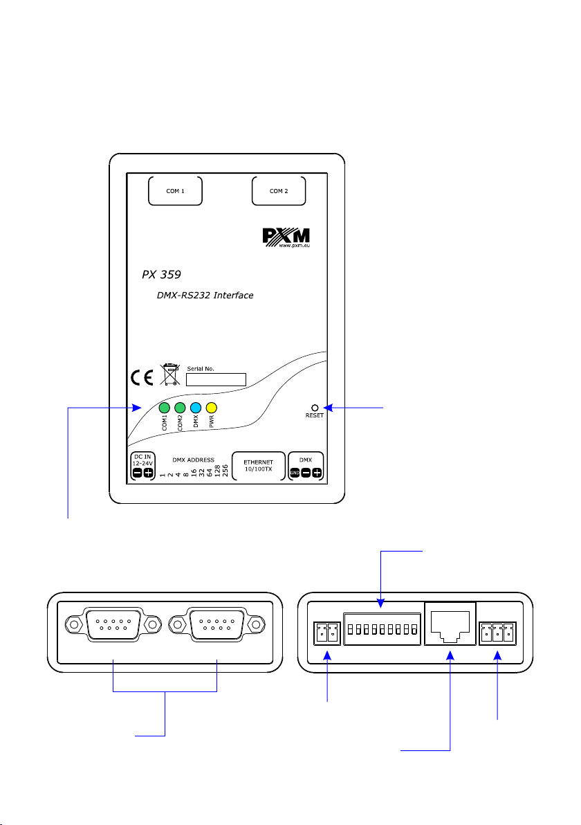
3. DESCRIPTION OF THE DEVICE CONSTRUCTION
PX359 is equipped with one Ethernet port, one DMX512 input, two RS-232 outputs, DIP switch to
set a DMX address and signalling diodes.
TOP OF THE DEVICE
physical reset button
signalling diodes
TOP OF THE DEVICE
RS-232 connectors
power supply
Ethernet power outlet
4
DMX address -
DIP switch
DMX512
inputs
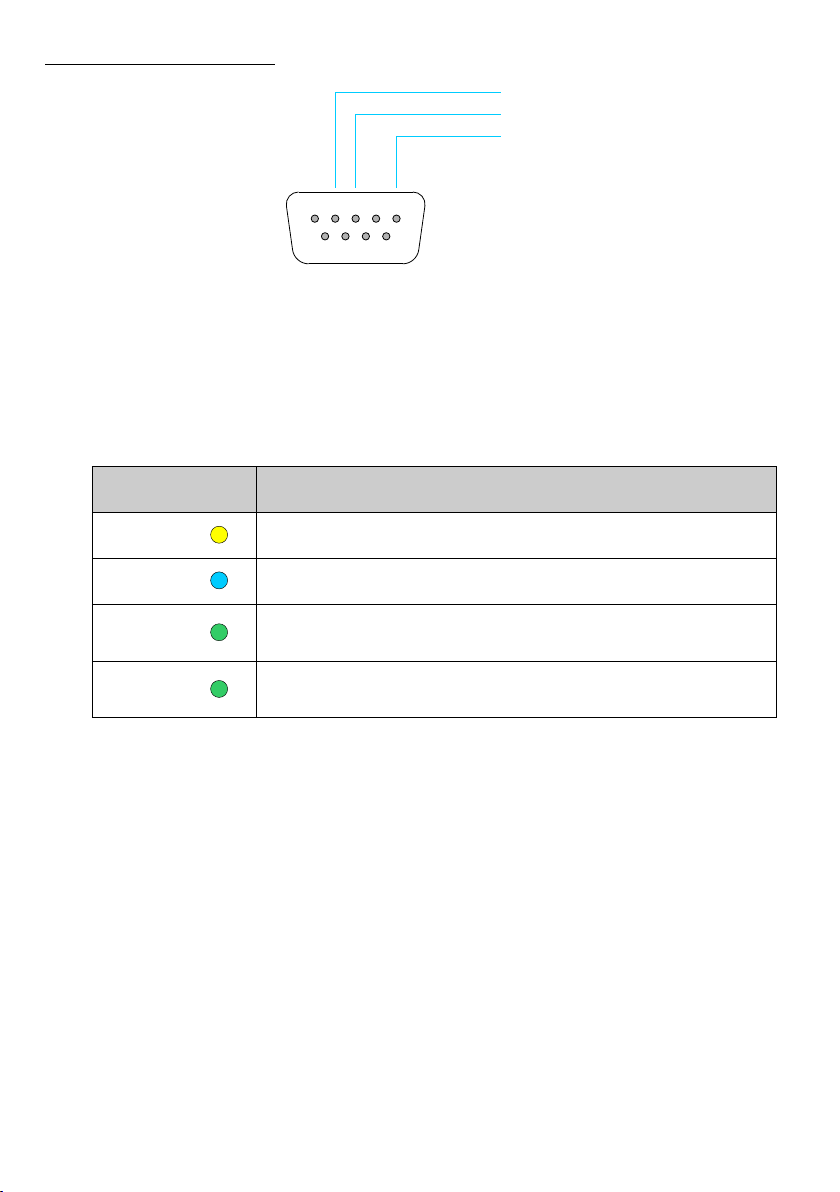
Control
Function
POWER
It is permanently on when the device is on
DMX
It blinks when the device receives a DMX signal
COM 1
It blinks every time when it sends a command
on the first RS-232 line
COM 2
It blinks every time when it sends a command
on the second RS-232 line
Description of the output pins:
RXD
TXDTXD
GND
4
1 2 3
6 7 8 9
5
4. OPERATION OF THE DEVICE
4.1. Sygnalling of controls
On the housing of the device there are four diodes signalling the condition of the device.
4.2. Reset button
On the housing of the device there is a button “reset.” Pressing it for a short time restarts the
device.
Pressing this button for a longer time (over 10 seconds) restores default settings. It will be
signalled by lighting all the diodes one after another.
4.3. Dipswitch of the address
The PX359 device has a physical dipswitch button which can be used to set its base DMX
address. If the value 0 is set on the physical switch, the device accepts the DMX address saved in
memory. Then, it can be edited by a webserver or the RDM protocol.
5
 Loading...