

PXM PX125 Opera RedLine Instruction Manual

INSTRUCTION
MANUAL
PX125
Opera
RedLine
R

CONTENTS
1. General description.............................................................................
2. Safety conditions.................................................................................
3. Front panel view..................................................................................
4. Controller and dimmers connection....................................................
5. Console activation...............................................................................
5.1. Operation mode selection.....................................................
6. Controller programming......................................................................
6.1. Scenes creation and edition..................................................
6.1.1. Scenes copying.....................................................
6.2. Chasers creation and edition................................................
6.3. Sequences creation and edition............................................
7. Scenes and chasers rendering...........................................................
8. Sequences rendering..........................................................................
9. PRESET operation mode....................................................................
10. Monitor................................................................................................
11. FLASH card: saving and reading........................................................
12. PC communication..............................................................................
13. Connections couplings........................................................................
14. Technical specification........................................................................
15. Declaration of conformity.....................................................................
1
1
2
3
3
4
4
4
6
6
9
10
12
13
14
15
16
17
17
18
Manufacturer reserves the right to make modifications in order to improve device operation.
PXM s.c.
ul. Przemysłowa 12
30-701 Kraków
POLAND
tel.: (+48 12) 626 46 92
fax: (+48 12) 626 46 94
E-mail: info@pxm.pl
Internet: www.pxm.pl

1. GENERAL DESCRIPTION
1
2. SAFETY CONDITIONS
PX125 Opera RedLine controller is powered from standard 230 V grid, what can cause
electric shock when safety rules are not observed. Therefore it is necessary to observe the
following:
1. The device can be connected to the mains through the enclosed power cable only.
2. Controller can be connected to socket which has protecting instalation in working order (3 wire grid) only.
3. Power cable should be protected against mechanical and thermal damage.
4. In the event of damaging the power cable, it should be replaced with a cable of the same
technical data and attestations.
5. All repairs demanding casing opening should be made with cut off power supply.
6. Controller should be strictly protected against contact with water and other liquids.
7. All sudden shocks, particularly dropping, should be avoided.
8. Device with damaged (cracked) casing should not be connected to the mains.
9. The device cannot be turned on in places with humidity exceeding 90%.
o o
10. The device cannot be used in places with temperature lower than 2 C or higher than 40 C.
11. Cleaning with damp duster only - PX125 has to be cut off the power supply.
directly
PX125 Opera Redline is a professional console for theatre and stage lighting control. In has a block
of 100 programmable channels of adjustable brightness, divided into 10 ranges, consisting of 10
channels each. Opera can store in the memory 100 scenes, 100 chasers (24 steps each) and 10
sequences, 100 steps each. It also has an additional, independent channel for, for instance,
auditorium lighting control. All the saved configurations can be modified freely by the operator,
including changes introducting during rendering. The chasers rendering speed and step-to-step
fader is adjusted with the potentiometers or synchronized with the music. The controller has no
limitation of number of concurrently rendered scenes and chasers.
The Complact Flash card socket allows to store the sequences, chasers and scenes.
By dint of possibility of colour monitor connection, the operator has a permanent visualization of
all controlled channels.
RS-232 coupling allows to connect the console to the computer, for settings storage or software
updates.
Opera is also equipped with the DMX-512 output.
2
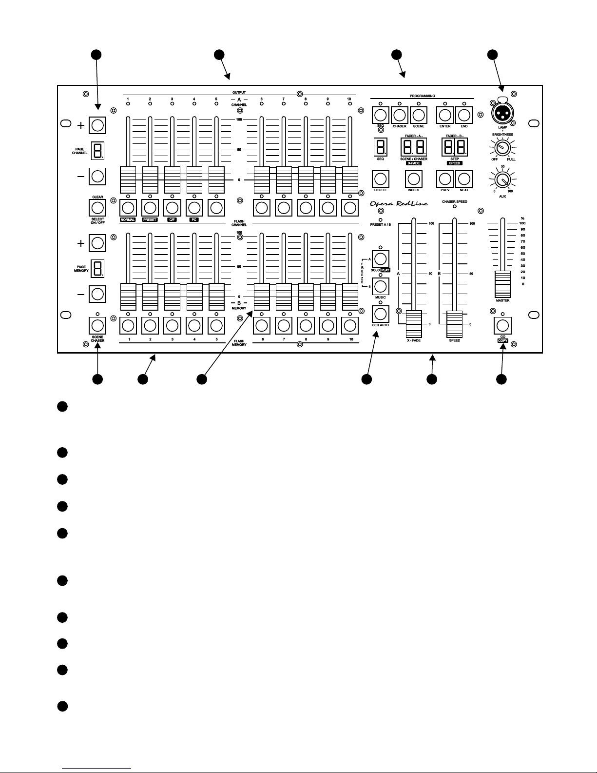
3. FRONT PANEL VIEW
6
These keys serve for selection of scene or chaser for programming or edition. In the
rendering mode these keys launch a scene or chaser with maximal brightness.
SCENES / CHASERS
SELECTION KEYS
SCENES / CHASERS
BANK SELECTION
5
7
These keys launch the ascribed to them scene or chaser.
4
LAMP SOCKET
12 V lamp connection socket. The knob below allows to adjust the brightness.
3
PROGRAMMING BLOCK
Keys for scenes, chasers and sequences programming and edition.
2
CHANNELS
CONTROL SLIDERS
Control sliders for 10 channels of one bank. The slider operates when the LED below is lit.
1
CHANNELS BANK
SELECTION
100 channels are divided into 10 banks, 10 channels each. The digit, visible on the display,
represents the successive ten channels. The digit displayed under the key represents the
channel number within one bank.
100 scenes and chasers are divided into 10 banks, 10 scenes or chasers each. The digit,
visible on the display, represents the ten successive scenes or chasers. The digit displayed
under the key represents the successive number within one bank.
1
6
5
7
4
3
2
8
9
10
8 9
10
SCENES / CHASERS
ADJUSTMENT SLIDERS
SEQUENCES LAUNCH
SUBMASTERS
AUTOMATIC
RENDERING
Launches the sequences rendering.
These sliders are for scenes changing during sequences rendering or controlling the
rendering speed and X-fade during chasers rendering.
Automatic sequences rendering start. During programming allows to replicate the scenes.
PUSH
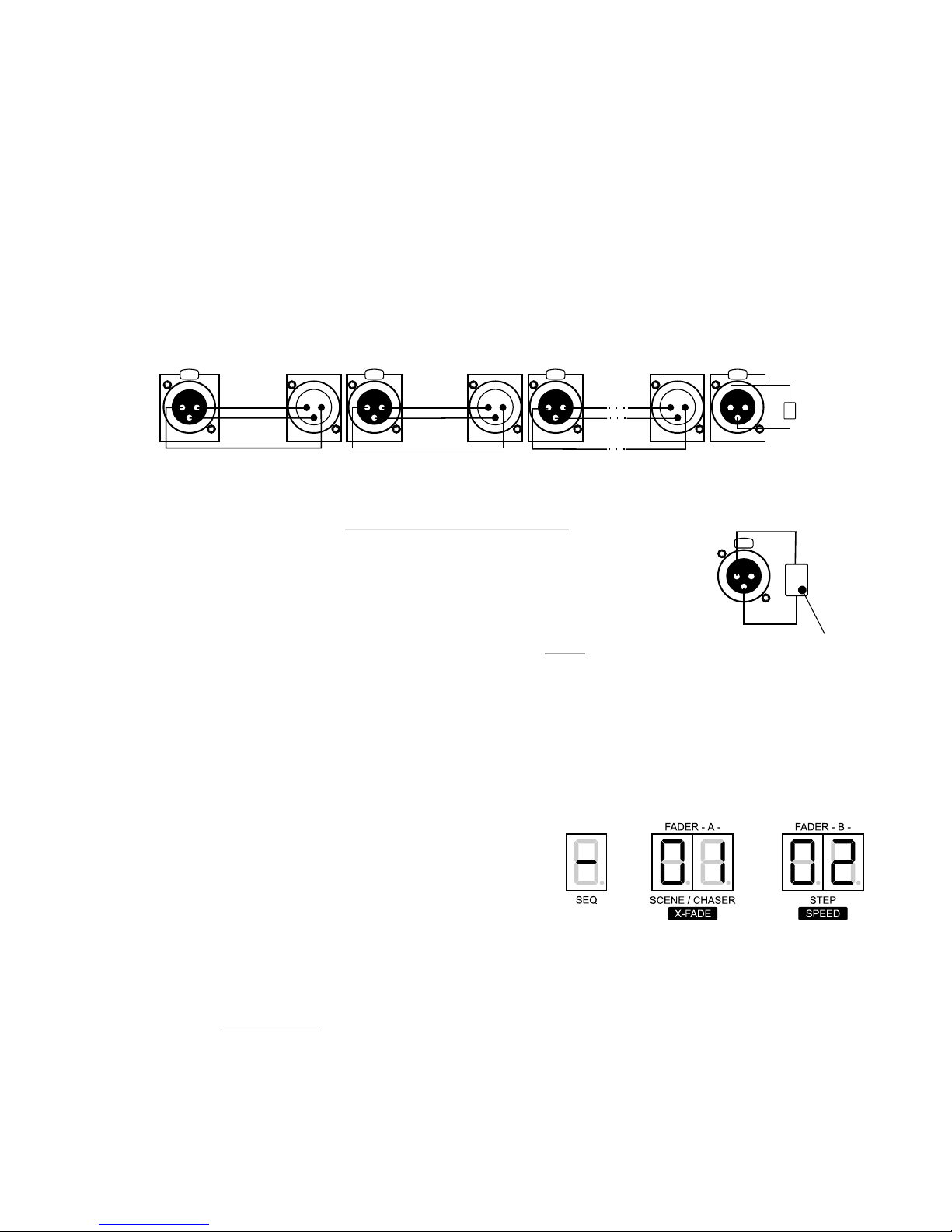
4. CONTROLLER AND DIMMERS CONNECTION
The Opera RL controller sends out the signals compatible with the DMX-512 standard. The
proper operation of the whole set of devices requires the correct DMX address settings in the
controlled devices and a correct devices' connection with a signal cable.
Below are some practical tips:
1. To connect the devices use of a 2-strand shielded microphone cable is recommended.
2. All the XLR couplings should be connected according to the following pattern:
pin 1 = shield pin 2 = DMX- pin 3 = DMX+
5. CONSOLE ACTIVATION
After switching the controller on (in NORMAL operation
mode) the controller's software version number is
displayed. In the example shown the software version
number is 1.02.
As the Opera RedLine software is permanently
improved, you can find the latest software version on the
producer's website. If its number is greater than
displayed, we recommend you to update your software.
The update process description and the software are
available on the www.pxm.pl website.
NOTICE:
By pressing any key you can enter the standard operation mode.
3
3. The controller and the effects must be connected in series, that is:
- the output of the controller to the input of the first effect,
- the output of the first effect to the input of the second effect,
- the output of the second effect to the input of the third effect, etc.
4. In the DMX OUT socket of the last effect the terminator must be installed
(XLR plug with the 110 Ohm resistor between 2 and 3 pins).
110 Ohm
resistor
110 Ohm
1
3
PUSH
2
110 Ohm
dimmer no. 1 dimmer no. 2
last dimmer
CONTROLLER
SHIELD SHIELD
DMX -
DMX +
DMX -
DMX +
1
2
3
PUSH
1
2
3
PUSH
1
2
3
PUSH
1
2
3
PUSH
2
1
3
2
1
3
2
1
3
terminator
6. CONTROLLER PROGRAMMING
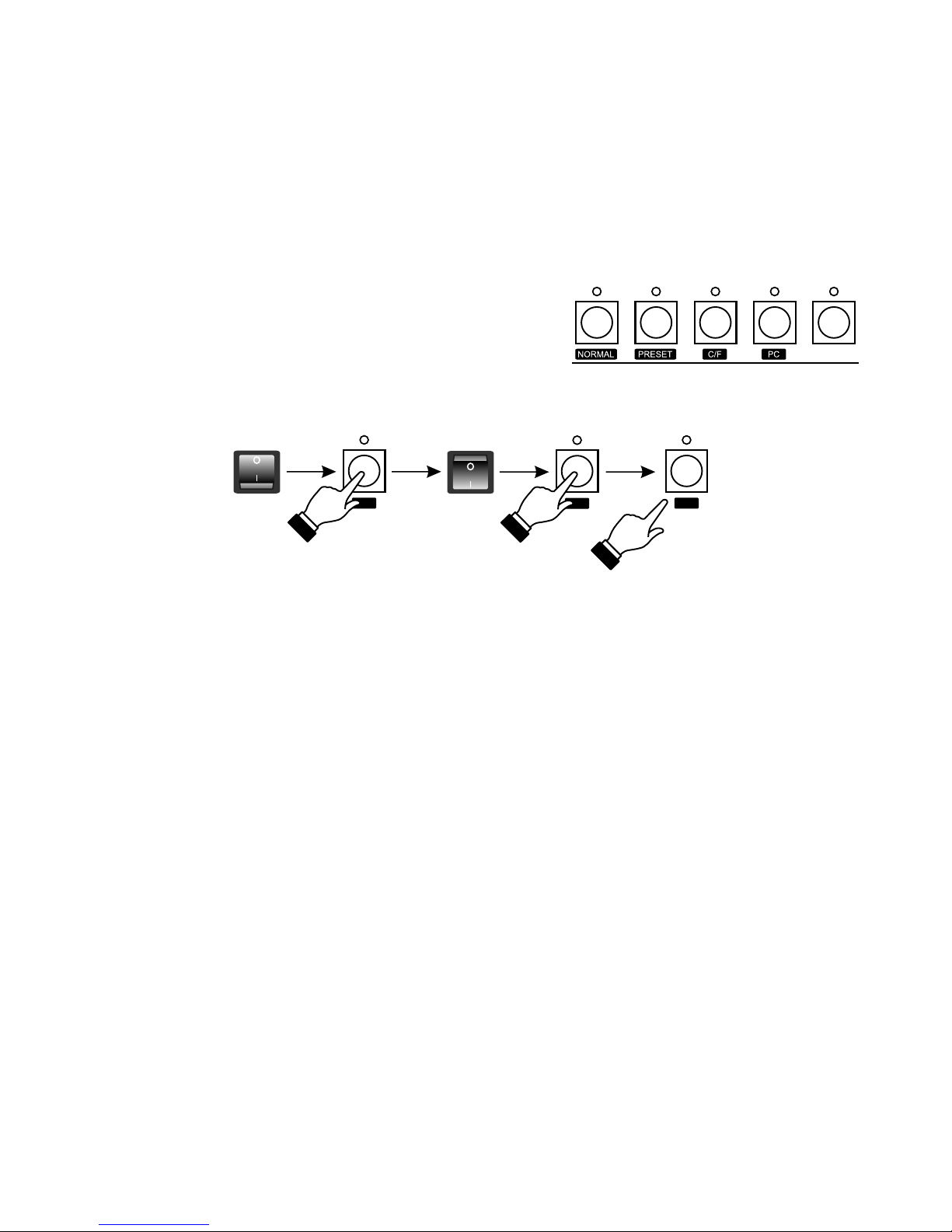
5.1. OPERATION MODE SELECTION
Opera RL controller can operate in one of the following modes:
1. NORMAL - basic operation mode,
2. PRESET - the "manual field" mode - the saving and rendering of the previously saved scenes,
chasers and sequences is off,
3. C/F - memory card communication mode - settings storage,
4. PC - computer communication mode - software updating, settings storage and edition.
The operation mode selection is being made during
controller switching on. To select an operation mode:
1. Switch the controller off.
2. Press and hold one of the keys shown - appropriate for
the selected mode.
3. While holding the key switch the controller on.
4. After 3 seconds approximately release the key.
ATTENTION:
The NORMAL and PRESET modes settings are saved in the controller's memory and the
controller will be automatically switched to one of this modes after turning on.
The C/F and PC modes are not saved. For that reason after turning the controller off and on again,
Opera RL will be automatically switched to the operation mode it run according to before the C/F
or PC modes were selected.
Switching to the selected mode is confirmed by:
- for the NORMAL mode - the software number is displayed,
- for the PRESET mode - the PRESET LED is lit,
- for the C/F mode - the "C" and "F" letters are displayed on the banks' displays,
- for the PC mode - the GO LED is lit.
4
6.1. SCENES CREATION AND EDITION
~3 secs
1. In the PROGRAMMING block press the SCENE key - the LED above will light up, what
confirms the scenes programming has begun.
2. Select a number for the programmed scene. To do so, with the PAGE MEMORY "+" or "-" key
select a range, where you want this scene to be placed and, with one of the MEMORY keys,
choose the precise number for this scene. The digit, visible on the PAGE MEMORY display,
represents the successive ten of scenes. If you want to, for instance, select 75 as the number of
your scene, with the "+" or "-" keys set 7, and then press the 5 key. Above this key the LED will
light up, and the number of the selected scene will be shown on the SCENE/CHASER display.
 Loading...