

PXM Mirage RedLine II, PX126 Instruction Manual

INSTRUCTION
MANUAL
Mirage
RedLine II
PX126
R

CONTENTS
1. General description.................................................................................................
2. Safety conditions.....................................................................................................
3. Controller and effects connecting............................................................................
4. Front panel description............................................................................................
5. Scenes programming..............................................................................................
5.1. Scene programming................................................................................
5.2. Scene edition..........................................................................................
6. Programs defining...................................................................................................
6.1. Program end marker................................................................................
6.2. End marker edition...................................................................................
6.3. Synchronization programming.................................................................
6.4. Special keys programming......................................................................
6.5. Collections (CUEs) programming............................................................
6.6. Speed programming................................................................................
6.7. MIDI assignments programming..............................................................
6.8. Scenes to instrument keys assignment...................................................
6.9. Synchronization to instrument keys assignment......................................
6.10. MIDI assignments deletion....................................................................
7. Programs rendering................................................................................................
7.1. One program rendering start...................................................................
7.2. Another program rendering start..............................................................
7.3. Program rendering stop...........................................................................
8. Collections (CUEs) rendering..................................................................................
9. Special keys............................................................................................................
9.1. Manual control.........................................................................................
10. Blackout feature......................................................................................................
11. Programs copying to SOLO RL controller...............................................................
12. Programs copying from SOLO RL controller...........................................................
13. Co-operation with a PC computer...........................................................................
14. Connection sockets.................................................................................................
15. Technical specification.............................................................................................
16. Declaration of conformity.........................................................................................
1
1
2
3
4
4
5
5
5
6
6
7
8
8
9
9
9
9
10
10
10
10
11
11
11
11
11
12
12
14
15
16
Manufacturer reserves the right to make modifications in order to improve device operation.
PXM s.c.
ul. Przemysłowa 12
30-701 Kraków
POLAND
tel.: (+48 12) 626 46 92
fax: (+48 12) 626 46 94
E-mail: info@pxm.pl
Internet: www.pxm.pl

1. GENERAL DESCRIPTION
1
ATTENTION:
2. SAFETY CONDITIONS
PX126 Mirage RedLine is powered from standard 230 V grid, what can cause electric
shock when safety rules are not observed. Therefore it is necessary to observe the following:
1. The device can be connected to the mains through the enclosed power cable only.
2. Controller can be connected to socket which has protecting instalation in working order (3 wire grid) only.
3. All the conductors should be protected against mechanical and thermal damage.
4. In the event of damaging any conductor, it should be replaced with a conductor of the same
technical data and attestations.
5. All repairs demanding casing opening should be made with cut off power supply.
6. Controller should be strictly protected against contact with water and other liquids.
7. All sudden shocks, particularly dropping, should be avoided.
8. Device with damaged (cracked) casing should not be connected to the mains.
9. The device cannot be turned on in places with humidity exceeding 90%.
o o
10. The device cannot be used in places with temperature lower than 2 C or higher than 40 C.
11. Cleaning with damp duster only - PX126 has to be cut off the power supply.
directly
For user comfort two modes of "moved slider" are available:
1. "10%" - the programmed device starts to react when the control slider has been moved for at
least 6 milimeters.
2. "interception" - the programmed device starts to react when the control slider's value exceeds
(regardless of the direction) the programmed value for the particular DMX channel.
For the description of selection of sliders' reaction mode see page 13.
PX126 Mirage RedLine II is a versatile DMX controller for scanners, stage lighting or advertising
lighting installations control. With PX126 the user can control any device compatible with the
DMX-512 standard, as the dimmers, smoke generators, colours' changers, central effects or
scanners and heads, for which the controller is mainly intended.
Mirage RL controls 256 DMX channels, that are divided into sixteen 16-channel groups. In a
single group the user can control one 16-channel device or a few devices, that are controlled
through lower number of DMX channels (eg. sixteen 1-channel dimmers).
As for the programming, the controller allows to define 48 programs, consisting of up to 1022
scenes. The entirely new feature is the possibility of simultaneous rendering of up to three
programs with the different speeds. The maintenance comfort is extended by the maximal
simplification of programs' saving and rendering processes.
By dint of RS-232 interface the Mirage controller can be connected to the PC computer.
ATTENTION:
DMX addresses setting example
for 16 16-channel scanners.
1
7 (97)
13 (193)
2 (17)
8 (113)
14 (209)
3 (33)
9 (129)
15 (225)
4 (49) 10 (145)
16 (241)
5 (65) 11 (161)
6 (81) 12 (177)
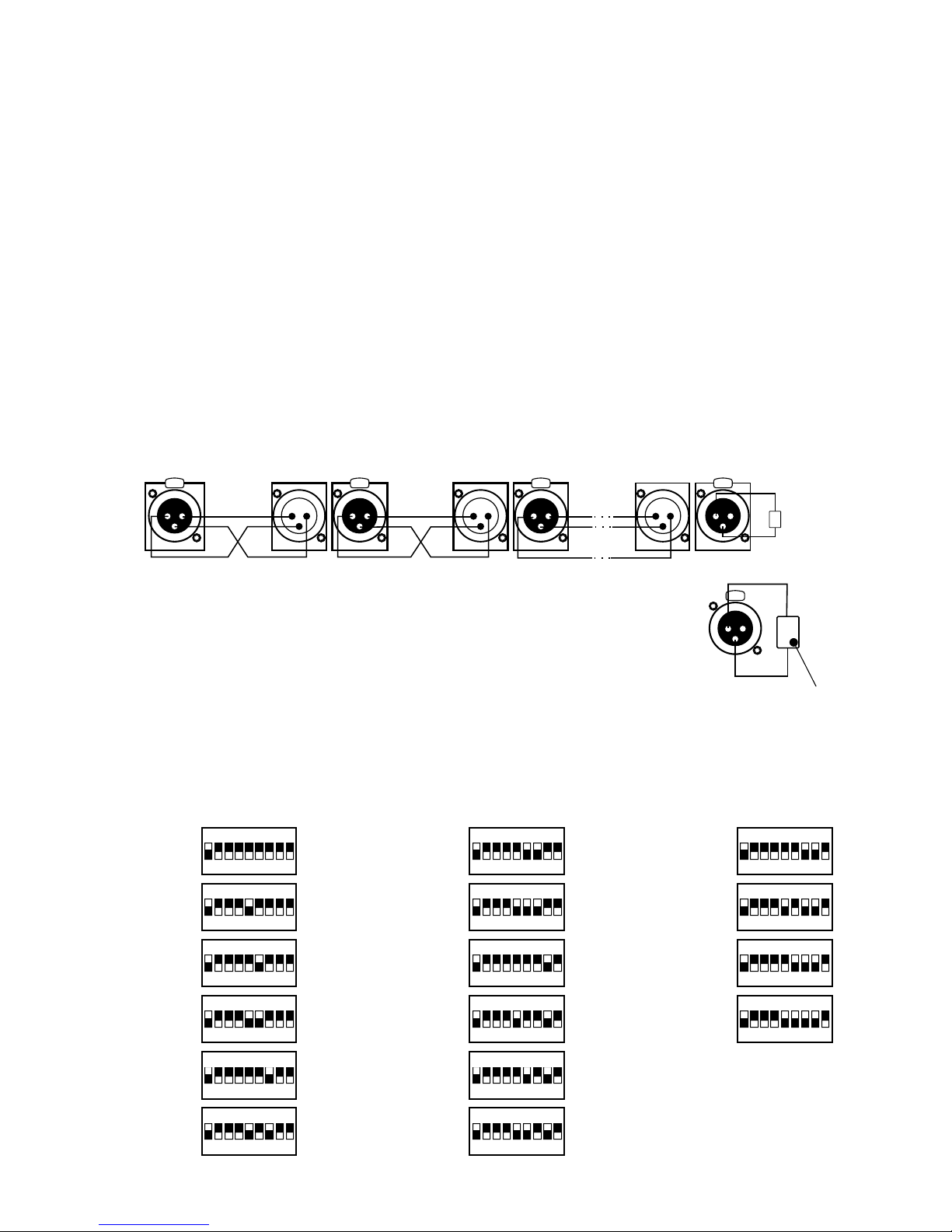
3. CONTROLLER AND EFFECTS CONNECTING
The Mirage controller sends out the signals compatible with the DMX-512 standard. The proper
operation of the whole set requires the correct setting of the DMX addresses in the controlled
devices and the correct connection between the devices, made with the signal cable.
Below are a few practical tips:
1. To connect the devices use a microphone cable (two strands in a shield).
2. Connect all the XLR couplings according to the following pattern:
pin 1 = shield pin 2 = DMX- pin 3 = DMX+
3. The controller and all the effects must be connected in series only, that is:
- the controller output to the first effect input,
- the first effect output to the second effect input,
- the second effect output to the third effect input, etc.
4. The "terminator" must be installed in the last device's DMX output socket
nd rd
(XLR plug with the 110 Ohm resistor between 2 and 3 pin installed).
5. Set the DMX addresses in the controlled effects according to the following pattern:
2
PRACTICAL COMMENT:
The older devices produced by MARTIN company have switched "DMX+" and "DMX-" lines. That
is why the special signal cables with interweaved signal lines should be prepared to connect
these devices.
2 3 4 5 6 7 8 9
ON
DIP
1
2 3 4 5 6 7 8 9
ON
DIP
1
2 3 4 5 6 7 8 9
ON
DIP
1
2 3 4 5 6 7 8 9
ON
DIP
1
2 3 4 5 6 7 8 9
ON
DIP
1
2 3 4 5 6 7 8 9
ON
DIP
1
2 3 4 5 6 7 8 9
ON
DIP
1
2 3 4 5 6 7 8 9
ON
DIP
1
2 3 4 5 6 7 8 9
ON
DIP
1
2 3 4 5 6 7 8 9
ON
DIP
1
2 3 4 5 6 7 8 9
ON
DIP
1
2 3 4 5 6 7 8 9
ON
DIP
1
2 3 4 5 6 7 8 9
ON
DIP
1
2 3 4 5 6 7 8 9
ON
DIP
1
2 3 4 5 6 7 8 9
ON
DIP
1
2 3 4 5 6 7 8 9
ON
DIP
1
110 Ohm
martin scanner no. 2
last scanner
CONTROLLER
SHIELD SHIELD
DMX -
DMX +
DMX -
DMX +
1
2
3
PUSH
1
2
3
PUSH
1
2
3
PUSH
1
2
3
PUSH
2
1
3
2
1
3
2
1
3
110 Ohm
resistor
110 Ohm
1
3
PUSH
2
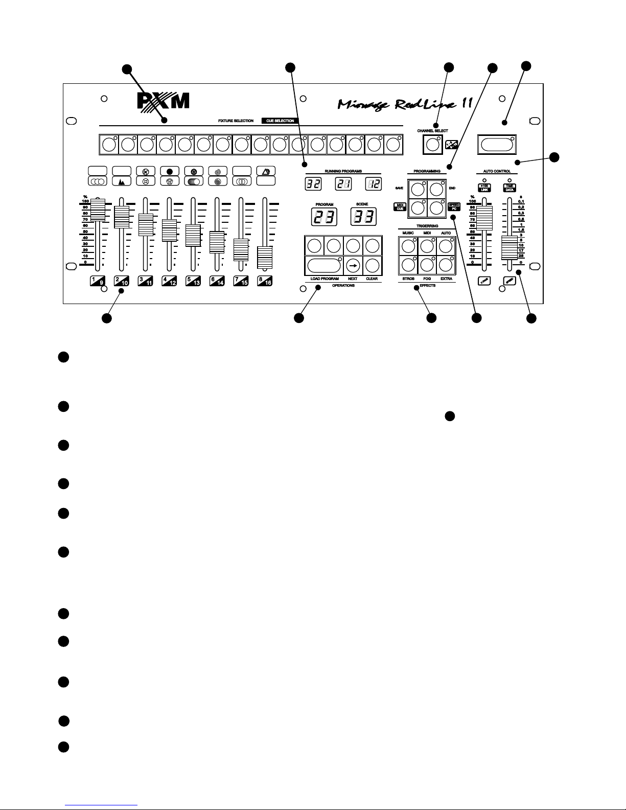
4. FRONT PANEL DESCRIPTION
3
6
"AUTO" MODE
RENDERING
CONTROL SLIDERS
RENDERING
SYNC BLOCK
With these keys you can select the synchronization mode during program rendering:
manual, automatic, to the music rhythm or MIDI signal.
5
7
INDICATORS
Rendering speed in the automatic mode and PC co-operation LED indicators.
These sliders change the parameters of programs' rendering in the automatic mode. The
"SPEED" slider adjusts the frequency of scenes changes. The "X-FADE" slider defines the
mode of step-to-step change - when set to the minimal position the change is instant, when
in maximal position, the change is totally smooth.
The set of displays, showing numbers of currently rendered programs.
11
4
SPECIAL EFFECTS
Three keys for loading the special effects (eg. stroboscope, smoke generator, etc.).
3
SCENES AND PROGRAMS
SELECTION BLOCK
The block contains the displays and the scene and program number selection keys.
"LOAD" starts rendering the selected program.
2
DMX CHANNELS
CONFIGURATION BLOCK
1
DEVICE SELECTION
BLOCK
Set of 16 keys for controlled device selection. The key activity status is indicated by an
appropriate LED. The control over the selected devices is executed in a DMX channels
configuration block.
9
PROGRAMMING BLOCK
This panel contains the keys used in the controller programming process. You can find
their exact description in the further part of the present manual.
8
BLACKOUT
When switching the "BLACKOUT" feature on, all the DMX channels are set to the zero
level, that means, all the effects are instantly dimmed.
RENDERED PROGRAMS
NUMBERS DISPLAYS
10
RANGE SELECTION
Key for the addresses range selection for the programmed device.
Sliders for 16 DMX channels control, corresponding to the selected devices. You can
switch between "1 - 8" and "9 - 16" channels ranges with the key.
10
6
5
3
2
10
1
8
4
9
7
11
BLACKOUT
1 2 83 4 5 6 7 9 10 1211 13 1614 15
TILT
+
IRIS
STATIC GOBO
ROTATING GOBO
PAN
+
GOBO ROTATION
U
<
<
STROBE
ZOOM
FROST
FOCUS
FILTER
SPECIAL FUN.1
FIXED PRISM
DIMMER
COLOR WHEEL
U
PRISM ROTATION
U
-
-
+
+
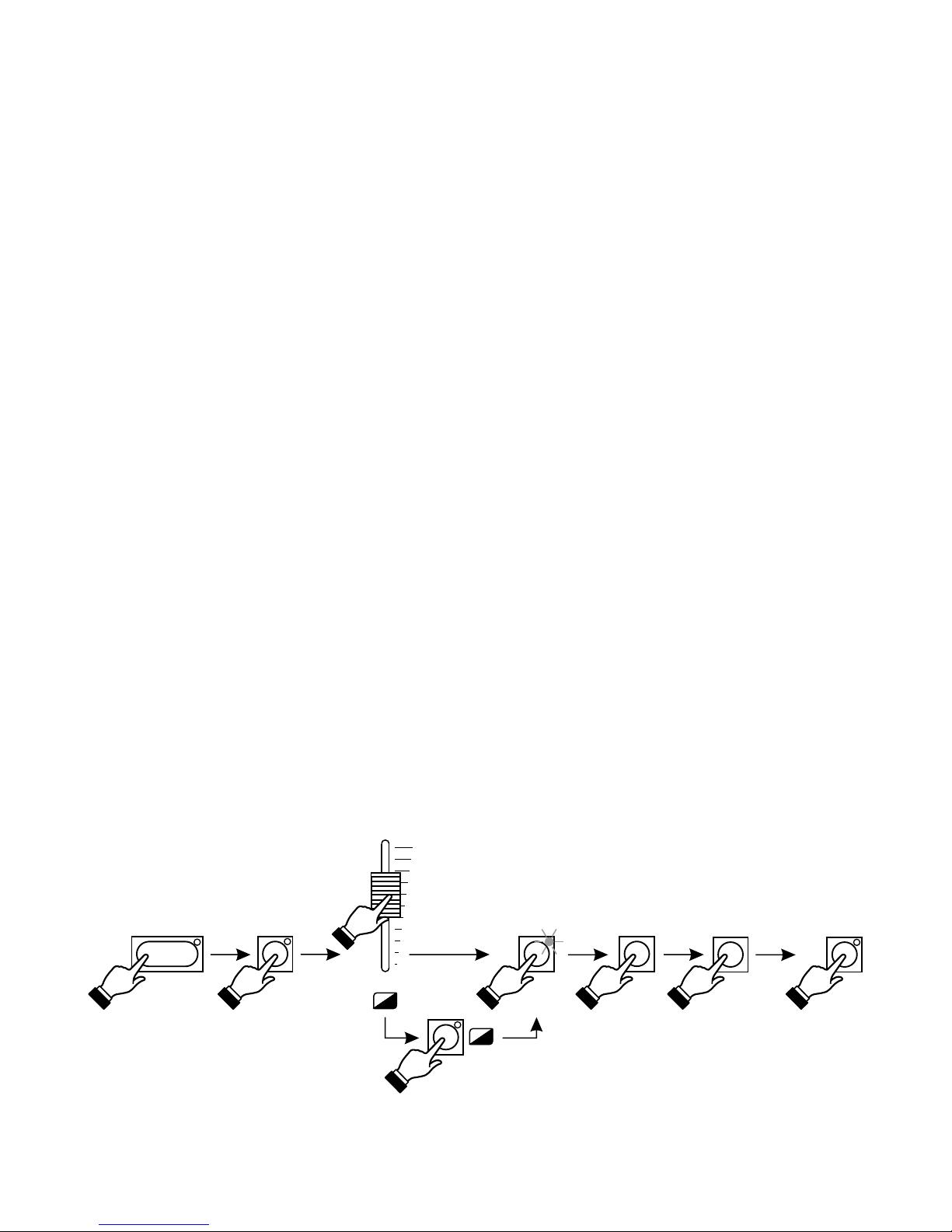
5.1. SCENE PROGRAMMING
5. SCENES PROGRAMMING
4
-
+
SAVE
1
-
8
9
-
1
6
CHANNEL SELECT
LOAD PROGRAM
3
3
11
SAVE
The controller programming lies in creating the scenes (1022 maximum), that are saved as the
programs' steps. A single scene has a full set of the control data for all 16 devices. The created
scenes can be modified freely, but you must remember, that saving the modified scene deletes
the previous one. During scene formation all the settings can be sent directly to the devices, so
the modifications' effect is visible in the room.
1. By pressing the "LOAD PROGRAM" key launch any program (on one of the RUNNING
PROGRAMS small displays its number will be displayed).
2. If any LEDs in the TRIGGERING block are lit, turn them off by pressing the corresponding keys.
3. In the FIXTURE SELECTION block press the key ascribed to the appropriate scanner - the
corresponding LED will light up. You can choose a few scanners at the same time (if they are of
the same kind only). In such case the settings (eg. GOBOs or colours) will be changed on the
slider movement in all the selected scanners concurrently.
4. Set the selected scanners according to your plans with the slider.
5. To get the access to channels 9 - 16 press the range selection key.
6. Press the "SAVE" key in the PROGRAMMING block - the corresponding LED will light up, that
means, the controller is ready to record.
7. With the left pair of "+" and "-" keys select the number of the program, where you want to save
the edited scene. With the right pair of "+" and "-" keys select the position, where you want to
place the scene in the sequence. Do not press the "LOAD PROGRAM" key during saving!
8. Press the "SAVE" key again. The LED will go out, that means, the changes have been saved in
the controller's memory. The scene programming process is finished.
To save another scene repeat the activities starting from point 3 or 4.
 Loading...