

PVI Industries EZ Plate Installation & Maintenance Manual
INSTALLATION & MAINTENANCE MANUAL
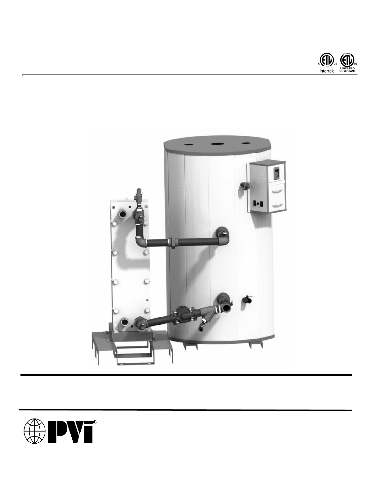
EZ PLATE® STORAGE WATER HEATER
Boiler Water Energy Source
Models (600-7200)(L)(150-4500)A(TRPF,TRBP)
Installation and service must be performed by a qualified service installer, service agency or qualified plumbing
contractor.
IMPORTANT: THIS MANUAL CONTAINS INFORMATION REQUIRED FOR INSTALLATION, OPERATION AND
MAINTENANCE OF THIS EQUIPMENT. READ AND FOLLOW THE INFORMATION IN THIS MANUAL AND ALL OTHER
PROVIDED INSTRUCTIONS, LABELS AND MARKINGS BEFORE INSTALLING, OPERATING OR SERVICING THIS
EQUIPMENT.
TO THE INSTALLER: After installation, these instructions must be given to the equipment user or left near the appliance.
SPECIAL INSTRUCTIONS TO THE OWNER: Retain this manual for future reference. These instructions contain
important information that will help you in maintaining and operating this appliance.
PVI INDUSTRIES, LLC – 3209 Galvez Ave. - Fort Worth, Texas 76111 - 1-800-433-5654
PV500-64 12/14

EZ Plate™ Storage Water Heater
TABLE OF CONTENTS
1 Safety Considerations
2 Product Descriptions
3 Water Heater Installation
3.1 Warranty
3.2 Checking Equipment Before You Install
3.3 Codes
3.4 Electrical Requirements
3.5 Handling and Locating the Water Heater
3.6 Service Clearances and Clearance to Combustibles
4 General Piping Guidelines
4.1 Potable Water Inlet and Outlet Connections
4.2 Storage Tank Relief Valve Piping
4.3 Cathodic Protection
4.4 Boiler Water Piping
4.5 Heat Exchanger Relief Valve Piping
4.6 Connecting Pump(s) and Valves (if equipped)
4.7 Filling the Unit
5 Operating and Safety Controls
5.1 Thermostat Settings
5.2 High Water Temperature Limit Controls
5.3 Electronic Low Water Cut-Off (optional)
6 Description of Operation
6.1 Sequence of Operation
7 Start-Up and Shut-Down Procedure
8 Maintenance
8.1 Temperature and Pressure Relief Valve
8.2 Thermostats and Temperature Limiting Device
8.3 Control Valve Actuator (if Supplied)
8.4 Tank
8.5 Heat Exchanger
8.6 Checking and Adjusting 2-Way or 3-Way Valve Operation
8.7 Recommended Maintenance Schedule
9 Troubleshooting Notes
10 Standard EZ Plate Storage Water Heater Wiring Diagrams
10.1 Point to Point Wiring Diagram
10.2 Ladder Diagram
Warranty forms ship separately with each water heater.
2
PV500-64 12/14
EZ Plate™ Storage Water Heater
1 SAFETY CONSIDERATIONS
WARNING: Do not use this appliance if any part has been under water. Immediately call a qualified service
technician to inspect the unit and to replace any part of the control system and any other items affecting safe
appliance operation and which has been under water. Failure to follow these instructions can cause property
damage, personal injury, or exposure to hazardous materials or death.
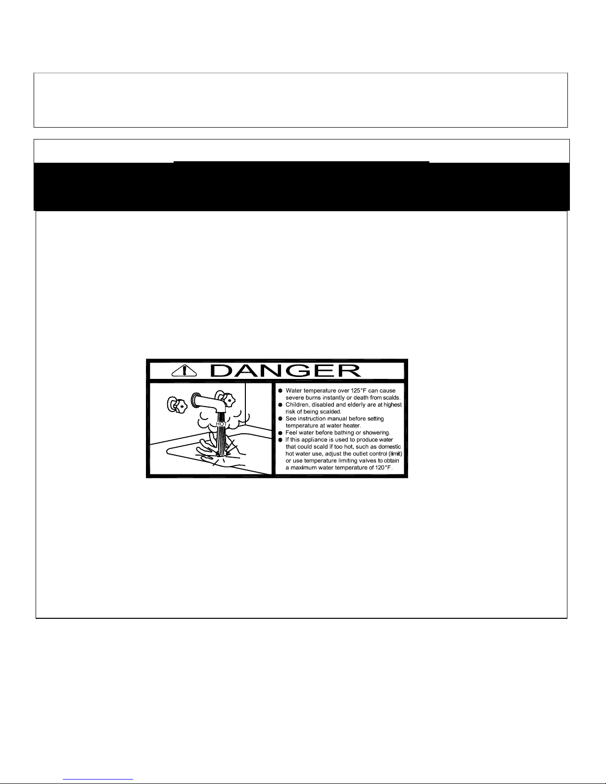
IMPORTANT SAFETY NOTE
It takes only 5 seconds of skin contact with 140 °F water to cause a
second degree burn! You must protect against high water temperatures at all
lavatories, tubs, showers and other points of hot water contact.
Accidental scalding from high water temperatures is a greater
risk in some types of installations. Some examples are:
HOMES FOR THE MENTALLY OR PHYSICALLY HANDICAPPED
HOSPITALS AND NURSING HOMES
ELDER CARE FACILITIES AND REST HOMES
ORPHANAGES AND CHILD CARE FACILITIES
OTHER INSTALLATIONS -
MAY BE SLOWER OR WHERE THE DANGER OF HOT WATER CONTACT IS GREATER.
WHERE RESPONSE TO CONTACT WITH HOT WATER
Thermostatically controlled mixing valves must be used in the design of
the potable hot water system. Potable hot water should be tempered to no
more than 110°F when used for bathing or other personal uses.
Good engineering practice mandates the use of thermostatically
controlled mixing valves set at 120°F or less to keep the delivered water
temperature below scalding temperatures.
3
PV500-64 12/14
2 PRODUCT DESCRIPTION
EZ Plate™ Storage Water Heater
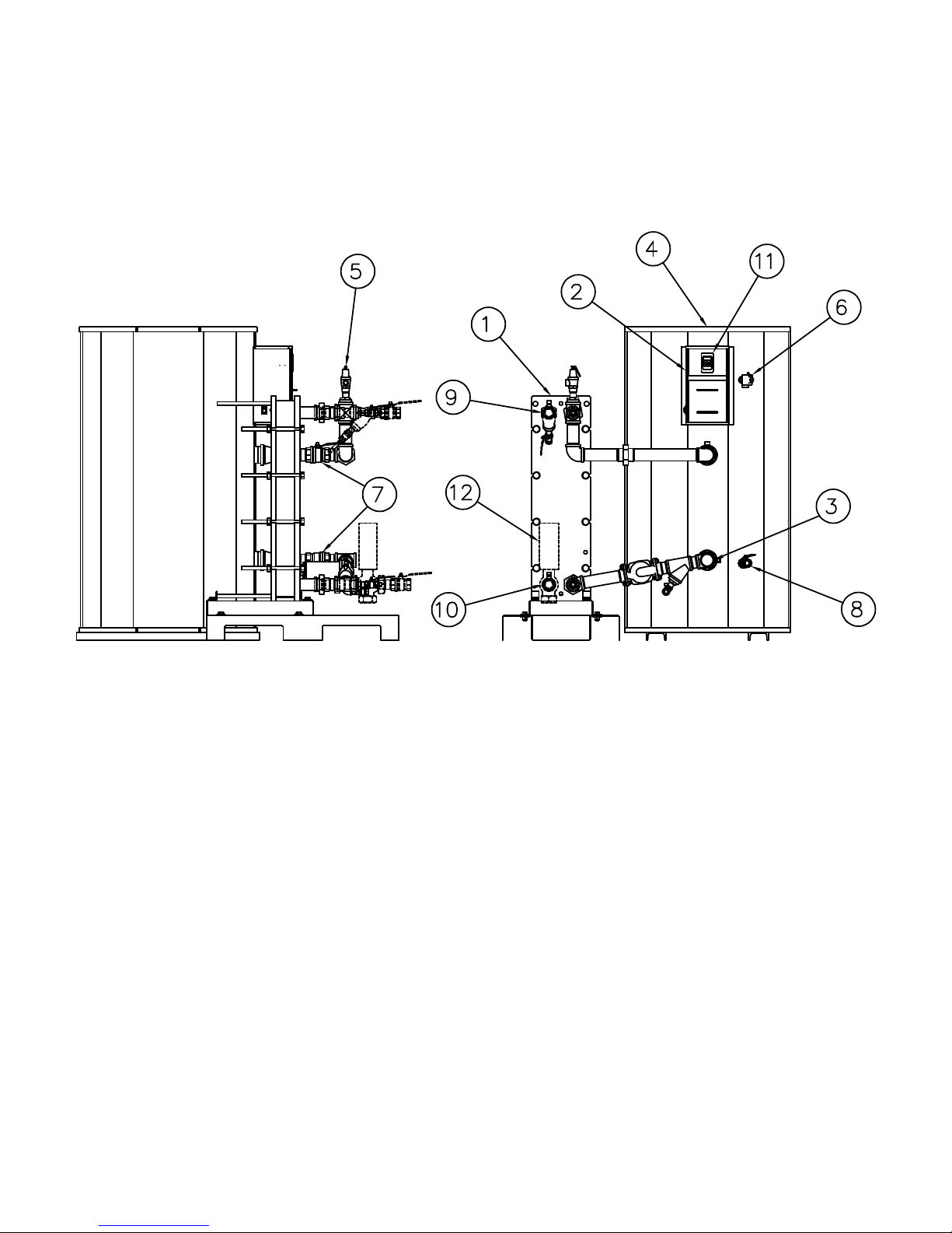
Typical EZ Plate™ Storage Water Heater Construction
1. Heat Exchanger (Heat Engine) 7. Isolation Shutoff Valves
2. Control Enclosure 8. Tank Drain Valve
3. Potable Water Inlet 9. Boiler Water Inlet
4. Potable Water Outlet 10. Boiler Water Outlet
5. Heat Exchanger Pressure Relief Valve 11. Electronic Operating Control
6. Tank T&P Relief Valve 12. Boiler Water Control Valve (optional)
NOTE: Components, controls and connection locations may vary.
4
PV500-64 12/14

EZ Plate™ Storage Water Heater
3 WATER HEATER INSTALLATION
3.1 Warranty
Factory warranty does not cover improper installation or operation. (See warranty for complete details).
Warranty exclusions include but are not limited to failure or malfunctions resulting from:
1. Failures to properly apply, install, operate, or maintain the appliance in accordance with printed instructions.
2. Abuse, alteration, accident, fire, flood and the like.
3. Sediment or lime buildup, freezing or any other conductions causing inadequate circulation.
4. Corrosive or contaminated atmosphere.
3.1 Checking Equipment Before You Install
Inspect the unit completely upon receipt from the freight carrier before signing the bill of lading. Inspect the appliance
and all accompanying parts for signs of impact or mishandling. Verify the total number of pieces shown on packing
slips with those actually received. Contact the freight carrier immediately if any damage or shortage is detected.
3.2 Codes
The equipment must be installed in accordance with the instructions in this manual, appliance markings and
supplemental instructions and in compliance with those installation regulations in force in the local area where the
installation is to be made. These must be carefully followed in all cases. Authorities having jurisdiction must be
consulted before installation is made. In the absence of such regulations, the installation must be in accordance with
the instructions in this manual, appliance markings, supplemental instructions and in compliance with the latest
edition of the applicable state and local mechanical and plumbing codes. The storage tank conforms to the current
edition of the ASME Boiler and Pressure Vessel Code Section IV, Part HLW and the plate heat exchanger conforms
to the current edition of the ASME Boiler and Pressure Vessel Code Section VIII.
3.3 Electrical Requirements
This appliance is wired for 120VAC/1ph/60Hz service, as standard (check decal on product). The appliance must be
electrically grounded in accordance with the requirements of the authority having jurisdiction or in the absence of
such requirements, with the latest edition of the National Electrical Code ANSI/NFPA No. 70. When the unit is
installed in Canada, it must conform to the CAE C22.1, Canadian Electrical Code and/or Local Electrical Codes.
• Supply the electrical service specified on the water heater data decal to each water heater. Separate electrical
circuits are recommended for multiple appliance installations.
• Branch circuit protection and a disconnecting means must be furnished by the installer. Refer to the provided
wiring diagram when installing or troubleshooting electrical components of this appliance.
• All wiring between the water heater and field installed devices must be made with type T copper wire of proper
size for the appliance load. Damage resulting from use of aluminum wiring is not covered by the product warranty.
• Line voltage wire exterior to the water heater must be enclosed in approved conduit or approved metal clad cable.
• Protect all water heater internal and external electrical components, wiring and electrical service connections from
water (dripping, spraying, rain, etc.) at all times.
Utiliser du fil de cuivre de la taille appropriée pour le service électrique entrant. Les dommages résultant de
l'utilisation de fil d'aluminium seront exclus du champ d'application de la garantie de cet appareil.
3.4 Handling and Locating the Water Heater
WARNING: Use industry standard safe rigging methods, such as including the use straps and spreader bars
and lifting from the water heater base skid assembly, when attempting to lift or move this product. Failure to
follow industry standard safe rigging methods can cause uncontrolled tipping or dropping the water heater,
resulting in property damage, personal injury or death.
1. Do not attempt to move or lift the water heater by the plumbing connections or heat exchanger. Lift only by the
skid using industry standard safe rigging methods.
2. Locate the water heater in a clean and dry area as close as possible to the greatest hot water usage and as near
to boiler water and/or electrical power as practical.
3. Confirm that the system utilities are adequate to meet the water heater requirements on the information decal.
5
PV500-64 12/14

EZ Plate™ Storage Water Heater
4. These water heaters are suitable for indoor installation only and must not be subject to freezing.
5. The water heater must be placed on a level surface. Installation on a 4 inch to 6 inch housekeeping pad is
recommended.
6. Locate the water heater so that if water connections should leak, water damage will not occur. Water damage is
not covered by the manufacturer’s warranty.
7. Locate the water heater near a suitable drain capable of accepting hot water discharge (potentially in excess of
210°F) from the water heater temperature and pressure relief valve
8. Once the water heater storage tank and heat engine are placed in their final location, carefully remove all
shipping supports and bracing.
3.5 Service Clearances and Clearance to Combustibles
Service Clearance: A minimum service clearance of 18" is recommended on all sides and above the appliance to
facilitate easy access for inspection and service of installed components. Optional equipment may increase the
clearance requirements.
Also allow sufficient space for installing and servicing connections such as building water, electrical, pump, boiler
water and other auxiliary/optional equipment.
Clearance to combustibles: A minimum clearance to combustible materials of 6” is required.
Un dégagement minimal aux matériaux combustibles est de seize cm (16 cm) est nécessaire.
4 GENERAL PIPING GUIDELINES
4.1 Potable Water Inlet and Outlet Connections
CAUTION: To maintain tank corrosion resistance and warranty, do not contact inside (water side) of tank, nozzles or
stainless steel fittings with ferrous (i.e. iron or steel) metal, tools, brushes, etc.
IMPORTANT: Do not use di-electric nipples, galvanized pipe or fittings or steel pipe or fittings when making
waterside connections. Use only non-ferrous waterside materials.
1. All domestic and boiler water pipes should be flushed before assembly and installation. Failure to flush lines
could cause components to clog or malfunction.
2. To avoid shipping damage, some piping assemblies may be disconnected and separately secured to the
shipping container. Such assemblies must be reconnected. Align and re-connect the heat engine potable water
lines to the storage tank as shown in the product description. If necessary, the storage tank and heat engine can
be relocated by the customer using field-supplied piping. A larger field-supplied pump may be necessary when
increasing the distance between the heat engine and the tank.
3. Always use a back-up wrench on tank and heat engine piping when tightening unions, valves, flanges, etc.
Damage caused by plumbing mistakes, such as over-tightening or not using a backup wrench is not covered by
warranty.
4. Piping and components connected to the water heater must be suitable for potable water, for the water
temperatures they will experience and for their application.
5. Install shut-off valves and unions in the potable water and boiler water inlet and outlet piping to aid in servicing.
Use caution when threading pipe nipples into tank and heat engine connections to prevent cross threading, or
over-tightening.
6. Thermal Expansion Tank – If the water heater is installed in a closed water supply system, such as one having a
back-flow preventer in the cold water line, provide thermal expansion control.
7. Pipe the Y-strainer blow-down valve and the storage tank drain valve to a suitable open drain capable of
accepting hot water at the temperature discharged when opening the water heater drain valve.
8. When two or more water heaters are piped in parallel it is important that the piping systems are balanced to
assure the full combined capacity is realized. Reverse return piping is recommended for multiple unit
installations.
9. Do not use the water heater or attached piping as an electrical ground of any kind.
10. After plumbing, confirm all connections, components and fittings are leak free.
6
PV500-64 12/14

EZ Plate™ Storage Water Heater
11. After checking for leaks, the heat exchanger and all boiler water and hot potable water piping must be
insulated to the minimum pipe insulation thickness specified in ASHRAE 90.1, “Energy Standard for Buildings
Except Low-Rise Residential buildings.” Insulate or otherwise protect cold water supply lines if subject to
freezing during operation or shutdown periods.
WARNING: Insulate or guard all surfaces containing hot water. Uninsulated or unguarded surfaces
containing hot water can be hot enough to cause severe burns instantly, if contacted. Failure to insulate or
guard all surfaces containing hot water can result in property damage, personal injury, or death.
Isoler ou protéger toutes les surfaces contenant de l'eau chaude.
4.2 Storage Tank Temperature and Pressure Relief Valve Piping
The EZ Plate water heater storage tank is supplied with temperature and pressure relief valve(s) sized in accordance
with the ANSI/ASME Boiler and Pressure Vessel Code, Section IV. The relief valve(s) must be threaded directly into
the dedicated relief valve fitting(s) located near the top of the storage tank and each relief valve discharge must be
separately plumbed to an appropriate floor drain. The discharge line must not be smaller than the relief valve
opening, must allow complete drainage of the valve and line and it must be positioned in the floor drain, such that
water or steam forcefully exiting the drain line does not openly splash.
The water heater must not be operated without a correctly installed, properly sized and properly operating relief
valve. If a replacement relief valve is required, it must be of the same type, temperature and pressure rating, and
relieving capacity as the original relief valve supplied with the water heater.
Do not plug or restrict the relief valve or the relief valve drain line.
It is strongly recommended that the relief valve(s) should be manually operated at least once a year. If water does
not freely flow from the manually operated relief valve or if it does not fully reseat when released, the relief valve
must be replaced with a new relief valve meeting the same ratings.
WARNING: Do not install a reducing coupling, valve or other restriction between the relief valve discharge
and a suitable floor drain. Such restriction could prevent the valve from fully relieving if the pressure
settings are exceeded, which could result in property damage, personal injury or death.
WARNING: Secure the relief valve piping to a suitable floor drain such that very hot water does not openly
splash during a significant relief valve discharge. If the relief valve pipe is not routed and secured to a
suitable drain, hot water discharge can result in property damage, scalding and personal injury or death.
IMPORTANT: Thermal Expansion - A relief valve that periodically discharges may result from thermal expansion. If
the water heater is installed in a system closed by components, such as a backflow preventer or check valve in the
cold water supply, the system must be provided with means to control expansion. Contact a water heater or
plumbing professional to resolve this situation.
4.3 Cathodic Protection
PVI water heaters do not utilize cathodic protection. However, in hot water systems containing other water heaters
that utilize cathodic protection, hydrogen gas can be produced when the hot water system has not been used for a
long period of time (generally two weeks or more). Hydrogen gas is extremely flammable. To prevent the
possibility of injury under these conditions, one of the hot water system faucets should be opened for several
minutes before using any electrical device connected to the hot water system. If hydrogen is present, there is
frequently an unusual sound such as air escaping through the pipe as the hot water begins to flow. Do not smoke,
have open flames or turn electrical switches on or off near the faucet at the time it is open.
7
PV500-64 12/14
EZ Plate™ Storage Water Heater
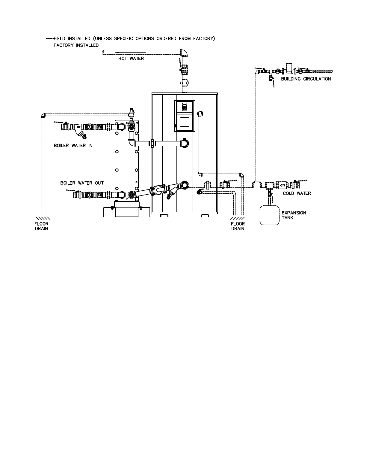
Typical EZ Plate™ Storage Piping Arrangement
4.4 Boiler Water Piping
WARNING: All system piping to the heat exchanger plumbing must be adequately supported. Failure to
provide adequate support will result in excessive loads on the heat exchanger connections that can cause
hot water discharge resulting in property damage, scalding and personal injury or death.
1. All boiler and domestic water pipes should be flushed before assembly and installation. Failure to flush lines
could cause components to clog or malfunction.
2. This water heater will perform in accordance with the boiler water and domestic water temperatures and flows to
which it is connected. To obtain the desired performance, it must be installed to operate with the temperature
and flow conditions specified when selecting the appliance. The boiler water piping must be sized to deliver
sufficient hot water to the heat exchanger without excessive pressure drop.
3. Always use a back-up wrench on tank and heat engine piping when tightening unions, valves, flanges, etc.
Damage caused by plumbing mistakes, such as over-tightening, cross threading or other installation damage is
not covered by warranty.
4. Install shut-off valves and unions in the boiler water and potable water inlet and outlet piping to aid in servicing.
Use caution when threading pipe nipples into tank and heat engine connections to prevent cross threading, or
over-tightening.
5. Obtain and install a Y-strainer, with a blow-down valve piped to a suitable drain, in the boiler supply piping near
the heat exchanger inlet. If the water heater is equipped with the optional factory installed 2-way on/off control
valve or 3-way diverting control valve, a factory installed Y-strainer and blow down valve is included and the
blow-down valve must be piped to a suitable drain.
6. Confirm an air separator in installed the boiler supply piping to the heat exchanger.
7. If a boiler water control valve is installed, maintain standard design practice to avoid “deadheading.”
8. When two or more heaters are piped in parallel it is important that the piping systems are balanced to assure the
full combined capacity is realized. Reverse return piping is recommended for multiple unit installations.
8
PV500-64 12/14
 Loading...