

PVI Industries CONQUEST 20 L 100 A-GCL, CONQUEST 25 L 100 A-GCL, CONQUEST 30 L 100 A-GCL Installation & Maintenance Manual

INSTALLATION & MAINTENANCE MANUAL
CONQUEST® WATER HEATER
MODELS (20, 25, 30) L 100 A-GCL
Installation and service must be performed by a qualified service installer, service agency or the gas supplier.
IMPORTANT: THIS MANUAL CONTAINS INFORMATION REQUIRED FOR INSTALLATION, OPERATION AND
MAINTENANCE OF THIS EQUIPMENT. READ AND FOLLOW THE INFORMATION IN THIS MANUAL AND ALL OTHER
PROVIDED INSTRUCTIONS, LABELS AND MARKINGS BEFORE INSTALLING, OPERATING OR SERVICING THIS UNIT.
TO THE INSTALLER: After installation, these instructions must be given to the equipment user or left near the appliance.
SPECIAL INSTRUCTIONS TO THE OWNER: Retain this manual for future reference. These instructions contain
important information that will help you in maintaining and operating this appliance.
PVI INDUSTRIES, LLC - Fort Worth, Texas 76111 - Web www.pvi.com - Phone 1-800-433-5654
PV500-66 07/15

CONQUEST® WATER HEATER
TABLE OF CONTENTS
1. Safety Considerations
2. Product Description
3. Water Heater Installation
3.1 Checking Equipment Before You Install
3.2 Codes
3.3 Electrical Requirements
3.4 Handling and Locating the Water Heater
3.5 Clearances to Combustible Surfaces
3.6 Service Clearances
3.7 Other Codes and Regulatory Clearances and Requirements
4. General Piping Guidelines
4.1 Inlet and Outlet Connections
4.2 Building Return Piping
5. Condensate Drain, Trap & Disposal
5.1 Condensate Neutralization System (optional)
6. Gas Supply and Piping
6.1 Gas Train and Controls Certification
6.2 Gas Control Trains
6.3 Inlet Pressure
6.4 Manifold Pressure
6.5 Gas Piping Size
6.6 Appliance Isolation During Gas Supply Piping Pressure Test
6.7 Gas Connection
7. Combustion and Ventilation Air
7.1 Equipment Located in Confined Spaces
7.2 Maximum Allowed Remote Combustion Air Inlet Length
7.3 Remote Combustion Air Cap
7.4 Vertical or Horizontal Remote Air Duct Termination
7.5 Combining Remote Air Ducting
8. Venting
8.1 Venting the CONQUEST
8.2 Maximum Vent Length
8.3 Vertical or Horizontal Vent Termination
8.4 Combining Category IV Vent
8.5 Concentric Vent for Combustion Air and Exhausting Flue Products
8.6 Connecting to an Existing Vent System
2
PV500-66 07/15

CONQUEST® WATER HEATER
9. Operating and Safety Controls
9.1 Temperature and Pressure Relief Valve(s)
9.2 Cathodic Protection
9.3 Electronic Low Water Cut-off
9.4 Operating Temperature Control
9.5 High Water Temperature Limit Control
10. TEMPTRAC Electronic Controller Panel
10.1 Principal of Operation
10.2 Upper LED Readout
10.3 Lower LED Readout
10.4 Control Buttons
10.5 To View the Setpoint
10.6 To Change the Setpoint
10.7 To Change Other Parameters
10.8 LED Display Alarm Messages
11. Remote Connections – Terminal Strip
11.1 Making BMS/BAS Remote Connection for Analog and Binary Signals
11.2 Terminal Functions
12. Sequence of Operation
13. Initial Startup
13.1 Initial Startup Requirements
13.2 Tools and Instrumentation Required
13.3 Resources
13.4 On Site Considerations
13.5 Startup Procedure
14. NSF Food Service Installation Guidelines
15. Troubleshooting Guide
16. Replacement Parts
16.1 Burner Assembly
16.2 Control Panel Enclosure Component Layout and Replacement PN’s
16.3 Component Wiring and Conduit Routing Details
17. Periodic Maintenance
18. Recommended Maintenance Schedule
Warranty forms ship separately with each product.
3
PV500-66 07/15
CONQUEST® WATER HEATER
1 SAFETY CONSIDERATIONS
WARNING: If the information in the supplied manual(s) is not followed exactly, a fire, explosion or exposure to
hazardous materials may result, causing property damage, personal injury or death.
AVERTISSEMENT. Assurez-vous de bien suivre les instructions données dans cette notice pour réduire au
minimum le risque d’incendie ou d’explosion ou pour éviter tout dommage matérial, toute blessure ou la mort
FOR YOUR SAFETY
• Do not store or use gasoline or other flammable vapors or liquids in the vicinity of this or any other appliance.
• Ne pas entreposer ni utiliser d’essence ou ni d’autres vapeurs ou liquides inflammables à proximité de cet appareil ou de
tout autre appareil.
WHAT TO DO IF YOU SMELL GAS
• Do not try to light any appliance.
• Do not touch any electric switch; do not use any phone in your building.
• Immediately call your gas supplier from a location away from your building and the smell of gas. Follow the gas
supplier's instructions.
• If you cannot reach your gas supplier, call the fire department.
QUE FAIRE SI VOUS SENTEZ UNE ODEUR DE GAZ:
• Ne pas tenter d’allumer d’appareil.
• Ne touches à aucun interrupteur; ne pas vous server des téléphones se trouvant dans le bâtiment.
• Appelez immediatement votre fournisseur de gaz depuis un voisin. Suivez les instructions de fournisseur.
• Si vous ne pouvez rejoinder le fournisseur, appelez le service de incendies.
Installation and service must be performed by a qualified installer, service agency or the gas supplier.
L’installation et l’entretrien doivent être assurés ou un service d’entretien qualifié ou par le fournisseur de gaz.
This product contains, or may come to contain materials that have been identified as carcinogenic, or possibly carcinogenic
to humans. Before installing, servicing or removing this product, read and follow the supplied instructions
Clearance in accordance with the local installation codes and the requirements of the gas supplier.
Dégagement conforme aux codes d’installation locaux et aux exigencies du foumisseunde gaz.
Should overheating occur or the gas supply fail to shut off, turn off the manual gas control valve to the appliance.
En cas de surchauffe ou si l’alimentation en gas ne s’arrête pas, fermez manuellement le robinet d’arrêt de l’admission de
gaz.
WARNING: Installation and service must be performed by a qualified installer, service agency or the gas supplier,
who must read and follow the supplied instructions before installing, servicing or removing this appliance. Refer to
the information contained in this manual. Improper installation, adjustment, alteration, service or maintenance can
cause property damage, personal injury, exposure to hazardous materials or death.
WARNING: Do not use this appliance if any part has been under water. Immediately call a qualified service
technician to inspect the unit and to replace any part of the control system, all gas controls and all other items
affecting safe appliance operation and which has been under water.
AVERTISSEMENT: N’utilisez pas cet appareil s’il a été plongé dans l’eau, même partiellement. Faites inspecter
l’appareil par un technicien qualifé et remplacez toute partie du système de contrôle et toute commande qui ont été
plongés dans l’eau.
WARNING: In an emergency shut the main gas supply valve to the appliance from a location safely away from the
emergency. Failure to follow these instructions can cause property damage, personal injury, and exposure to
hazardous materials or death.
4
PV500-66 07/15
CONQUEST® WATER HEATER
PRODUCT SAFETY INFORMATION
WARNING: This product contains or may come to contain crystalline silica, which has been identified by the
International Agency for Research on Cancer (IARC) as carcinogenic to humans. This product also contains
refractory ceramic fibers, which have been identified by the IARC as possibly carcinogenic to humans. Avoid
breathing fiber particulates and dust.
RISKS:
• Air borne fibrous insulation is a possible cancer hazard by inhalation.
• Airborne crystalline silica may cause silicosis (lung disease) by inhalation.
• May cause temporary irritation to eyes, skin, and respiratory tract.
PRECAUTIONARY MEASURES:
• Minimize airborne fibers with engineering controls.
• Use NIOSH/MSHA approved respirators as required (see MSDS).
• Wear long sleeved, loose-fitting clothing, eye protection and gloves.
FIRST AID MEASURES: (If any of the irritations listed persists, seek medical attention)
• Eyes: Flush with water.
• Skin: Wash with soap and warm water.
• Ingestion: Do not induce vomiting. Get medical attention if gastrointestinal symptoms develop.
• Inhalation: Remove to fresh clean air.
WARNING: If you are unfamiliar with the safe handling of refractory ceramic fiber products, or if you wish additional
information prior to beginning any disassembly of the water heater or boiler that might expose refractory ceramic
fiber materials, contact: Unifrax Corporation, 2351 Whirlpool Street, Niagara Falls, NY 14305-2413, 1-800-322-2293.
IDENTIFICATION OF REFRACTORY CERAMIC FIBER MATERIALS (RCF):
The burner assembly utilizes RCF material. (The RFC materials are located within the product and not generally exposed
except during service, disassembly or assembly.)
REFRACTORY CERAMIC FIBER PRODUCT WITH CRYSTALLINE SILICA
5
PV500-66 07/15
CONQUEST® WATER HEATER
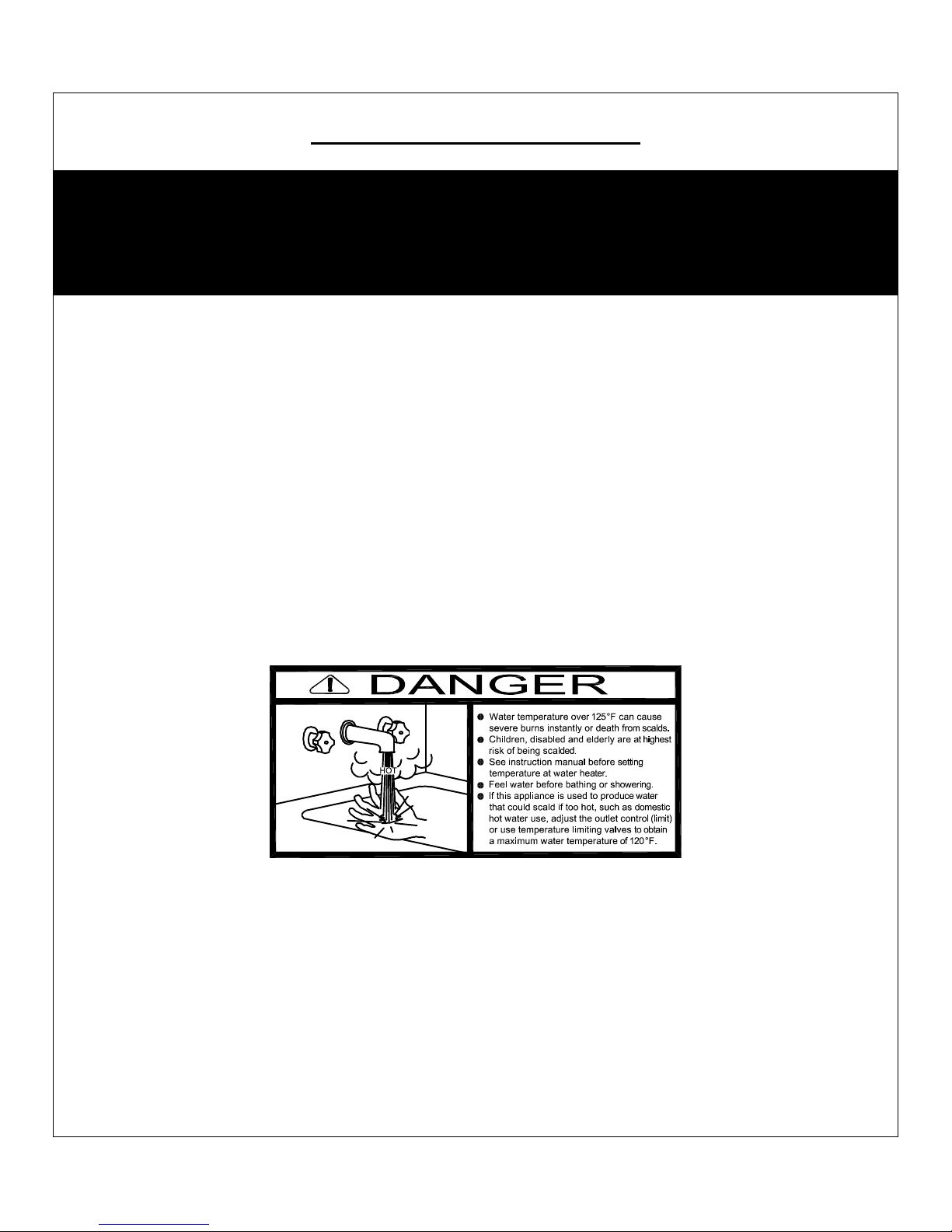
IMPORTANT SAFETY NOTE
It takes only 5 seconds of skin contact with 140°F water to cause a
second degree burn! You must protect against high water temperatures at all
lavatories, tubs, showers and other points of hot water contact.
Accidental scalding from high water temperatures is a greater
risk in some types of installations. Some examples are:
HOMES FOR THE MENTALLY HANDICAPPED
HOMES FOR THE PHYSICALLY HANDICAPPED
HOSPITALS AND NURSING HOMES
ELDER CARE FACILITIES AND REST HOMES
ORPHANAGES AND CHILD CARE FACILITIES
OTHER INSTALLATIONS - WHERE RESPONSE TO CONTACT WITH HOT
WATER MAY BE SLOWER OR WHERE THE DANGER OF
HOT WATER CONTACT IS GREATER
Thermostatically controlled mixing valves must be used in the
design of the potable hot water system.
Potable hot water should be tempered to no more than
110°F when used for bathing or other personal uses.
Good engineering practice mandates the use of thermostatically controlled
mixing valves set at 120°F or less to keep the delivered water
temperature below scalding temperatures
6
PV500-66 07/15
CONQUEST® WATER HEATER
2 PRODUCT DESCRIPTION Component, Controls and Connection Locations
(Locations May Vary)
7
PV500-66 07/15

CONQUEST® WATER HEATER
3 WATER HEATER INSTALLATION
3.1 Checking Equipment Before You Install
• Inspect the unit completely upon receipt from the freight carrier before signing the bill of lading. Inspect the
appliance and all accompanying parts for signs of impact or mishandling. Verify the total number of pieces shown
on packing slips with those actually received. Contact the freight carrier immediately if any damage or shortage is
detected.
• Check the data decal on the appliance. Be sure the electrical, water and gas supply is adequate for the
installation.
• Carefully remove all side and top shipping supports and bracing. If possible, do not remove the wooden base/skid
assembly until the product has been moved to its final location for installation and operation (see: Handling and
Locating the Water Heater).
3.2 Codes
The equipment must be installed in accordance with those installation regulations in force in the local area where the
installation is to be made. Authorities having jurisdiction must be consulted before installation is made. In the
absence of such requirements, the installation must be in accordance with the instructions in this manual, appliance
markings and supplemental instructions and in compliance with the latest edition of the National Fuel Gas Code,
ANSI Z223.1/NFPA 54. Where required by the Canadian authority having jurisdiction, the equipment must be
installed in accordance with the latest edition of the CAN/CSA B149.1-10 Natural Gas and Propane Installation Code
and applicable Provincial Regulations. All appliances conform to the current edition of the ASME Boiler and Pressure
Vessel Code, Section IV, Part HLW.
3.3 Electrical Requirements
See appliance rating decal for electrical service requirements. The appliance must be electrically supplied and
grounded in accordance with the requirements of the authority having jurisdiction or, in the absence of such
requirements, with the latest edition of the National Electrical Code ANSI/NFPA No. 70. In Canada, the electrical
service must conform to local electrical codes and/or CSA C22.1, Canadian Electrical Code, Part 1.
• All wiring between the unit and field installed devices must be made with type T copper wire.
• Line voltage wire exterior to the appliance must be enclosed in approved conduit or approved metal clad cable.
• To avoid serious damage, DO NOT energize the unit until the system and appliance is full of water.
Utiliser du fil de cuivre de la taille appropriée pour le service électrique entrant. Les dommages résultant de
l'utilisation de fil d'aluminium seront exclus du champ d'application de la garantie de cet appareil.
3.4 Handling and Locating the Water Heater
WARNING: Use industry standard safe rigging methods, such as strapping around the water heater
base/skid assembly and using spreader bars,
industry standard safe rigging methods can result in property damage, serious injury or death.
1 The water heater must be located indoors.
2 This water heater can be installed directly on a combustible floor.
3 Locate the water heater in an area that is not exposed to freezing temperatures.
4. Locate on a level surface. Installation on a 4 inch to 6 inch housekeeping pad is recommended.
5. Locate the water heater near a floor drain. Locate the unit so if the tank or water connections should leak, water
damage will not occur to the adjacent area or to lower floors of the building. When such locations are
unavoidable, install an adequately drained metal drain pan underneath the water heater. The manufacturer’s
warranty does not cover water damage.
6. Protect associated electrical components and electrical connections from water (dripping, spraying, rain, etc.)
during appliance operation and service.
7. Locate the water heater where the vent and air intake piping, when installed, will remain within the maximum
equivalent lengths allowed. See Venting.
when attempting to lift or move this product. Failure to follow
8
PV500-66 07/15
CONQUEST® WATER HEATER
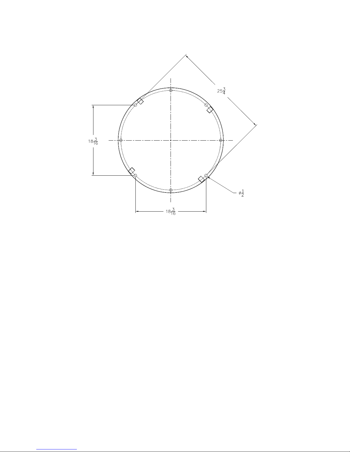
8. Use the following diagram to locate anchors or attachment points, when connecting the heater to the floor. Typical
concrete anchors: 5/16" x 1-3/4" double expansion shield
3.5 Clearances To Combustible Surfaces
The minimum clearance to combustible material is 15" from the top, 24" from the front and zero clearance (0") from
the sides and back of the water heater. The Conquest can be installed directly on a combustible floor.
Distance minimale aux matériaux combustibles est égale à zéro (0 cm) sur les côtés et à l'arrière, avant les 61 cm,
38 cm de haut et peut être installé directily sur un plancher combustible.
3.6 Service Clearances
Additional clearance beyond the minimum required to combustible material should be considered to facilitate easy
access for inspection and service of items such as the burner, gas controls and plumbing connections. Also allow
sufficient space for installing and servicing building water, gas, vent, combustion air, electrical, pump and other
auxiliary/optional equipment and connections.
3.7 Other Code and Regulatory Clearances and Requirements
Additional clearance beyond the minimum required to combustible materials and other requirements may be required
to comply with local, state or national codes and regulations. It is to the responsibility of the installer to comply with
these requirements. Examples of codes or regulations that may apply are the National Electric Code,
State/Regional/National drain water and flue emissions regulations, the National Fuel Gas Code, Building
Construction and Safety Codes, the Americans with Disabilities Act (ADA) and, in states where a water heater above
a certain input or storage capacity is considered a boiler, the applicable boiler code requirements, the applicable
boiler installation requirements in “Safety Code for Controls and Safety Devices for Automatically Fired Boilers”
(CSD-1) and other regulatory requirements.
9
PV500-66 07/15
CONQUEST® WATER HEATER
4 GENERAL PIPING GUIDELINES
4.1 Inlet and Outlet Connections
1. Use only non-ferrous water piping and fittings. Do not use galvanized pipe or fittings. Use of ferrous or galvanized
pipe or fittings can cause rust to form.
2. Install shut-off valves and unions on the inlet and outlet water piping for servicing. Use caution when threading
pipe nipples into tank connections to prevent cross threading, or over-tightening. Always use a back-up wrench on
tank nipples when tightening unions, valves, etc.
3. Insulate hot water and return circulation lines. Insulate cold water supply lines if subject to freezing during
shutdown periods. IMPORTANT: Do not use the plumbing connected to the appliance as a ground for welding or
any other purpose.
4. Pipe the drain valve to a suitable open drain capable of receiving discharge temperatures up to 212ºF.
IMPORTANT: Cold inlet water to the Conquest should not exceed 100ºF. Do not connect the building return or
dishwasher recirculation piping to the cold inlet water supply. The Conquest utilizes cold inlet water to help extract
almost all of the heat energy from the products of combustion, which lowers the vent temperature to allow the use of
PVC vent pipe. Higher cold inlet water temperatures will reduce heater efficiency and increase the vent temperature.
If the vent temperature approaches the maximum allowed, a vent temperature limit switch will cycle the heater off to
protect the PVC vent.
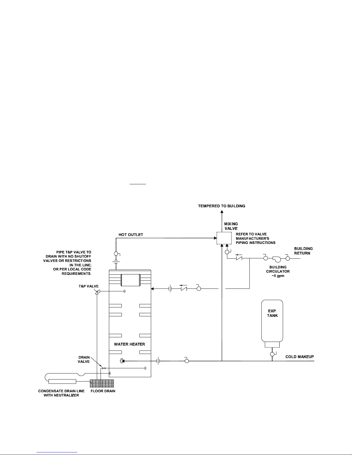
4.2 Building Return Piping
To maximize water heater efficiency, do not connect the building return or dishwasher recirculation piping (≈ 5 gpm)
directly to the cold inlet. Connect directly to the dedicated building return fitting located at the rear of the tank at midtank level.
SINGLE WATER PIPING
10
PV500-66 07/15
CONQUEST® WATER HEATER
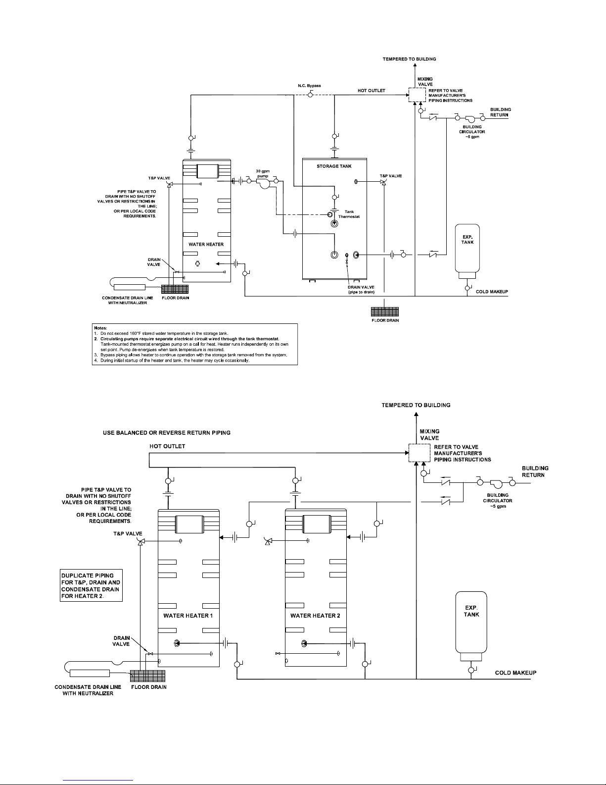
SINGLE STORAGE WATER HEATER WITH SUPPLEMENTAL STORAGE TANK
TWO WATER HEATERS WITH REVERSE RETURN PIPING
11
PV500-66 07/15
CONQUEST® WATER HEATER
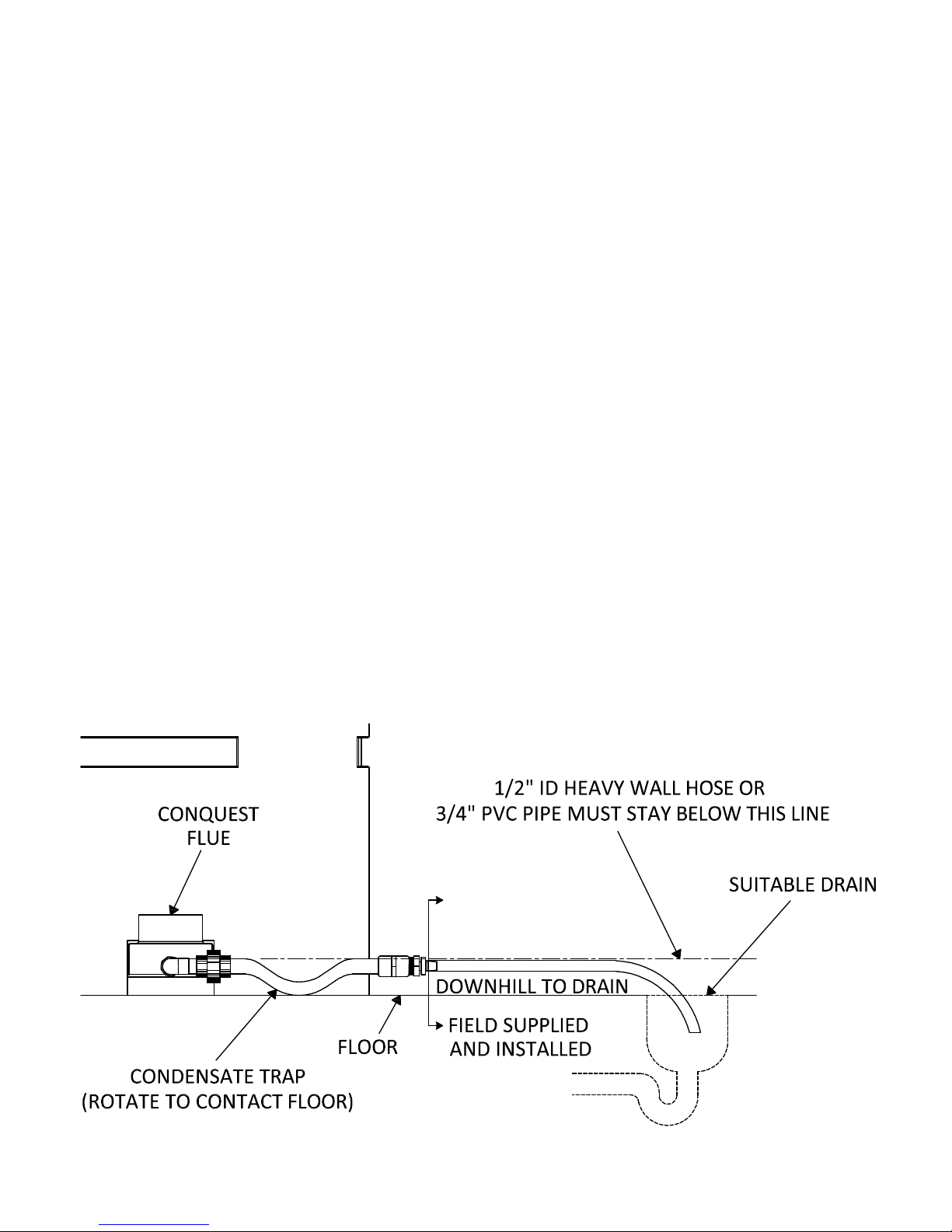
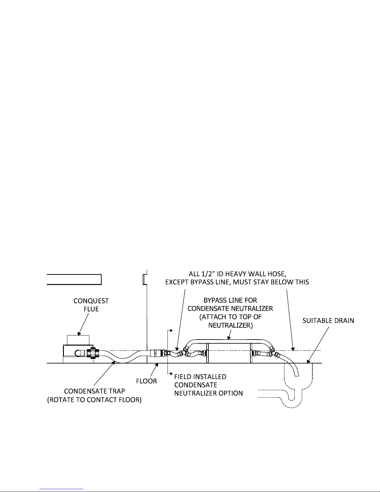
5 CONDENSATE DRAIN, TRAP & DISPOSAL
The Conquest water heater produces a significant amount of condensate. The condensate drain is under slightly
positive flue pressure, so the provided 3/4" PVC condensate trap must always be used. This trap is sized and
designed to fill with the proper amount of condensate to create a liquid barrier to prevent flue gases escaping through
the condensate drain into the installed space.
WARNING: The trap included with this unit must be installed and maintained as described in these
instructions and must be included as part of the condensate piping system. This trap is required to keep
hazardous products of combustion from continually entering the installed space where the condensate
piping terminates. Failure to properly install this trap can cause, personal injury, exposure to hazardous
materials or death.
1. Attach the 3/4" PVC fitting from the union on the condensate trap assembly to the PVC pipe exiting the flue
collector located near the front of the Conquest. Additional PVC fittings and pipe can be added to the flue
collector connection to relocate the condensate trap assembly as long as all added parts are at the same
elevation. After attachment, the trap must be rotated so the offset in the pipe aims down toward the floor. Do not
rotate the offset toward the ceiling. Do not use tools to tighten the PVC union. Hand-tighten the PVC union to
seat the internal gasket.
2. Do not combine condensate drains from multiple condensing appliances into a single drain line. Route each
drain line into a drain suitable for condensate and make certain the end of the drain lines are not submerged or
otherwise blocked.
3. All condensate plumbing must be protected from freezing. Do not locate the condensate piping such that an ice
dam of frozen condensate can block condensate from leaving the outlet.
4. The condensate is only slightly acidic (3-5 PH), however, local codes may require it to be neutralized prior to
entering the drainage system. An optional, field installed, Condensate Neutralization System is available from
the factory.
5. Connect a condensate drain line or the PVI Condensate Neutralization System to the barbed hose connection,
sized for 1/2" ID heavy wall Vinyl tubing rated for 170ºF or higher, located at the end of the condensate trap. All
piping from the condensate trap to the suitable drain must remain below the highest point (top of the
condensate outlet pipe) on the properly attached condensate trap.
Condensate Trap Without Optional Condensate Neutralizer
12
PV500-66 07/15
CONQUEST® WATER HEATER
5.1 Condensate Neutralization System (optional)
Condensate is only slightly acidic (3-5 PH), however this slight acidity can be neutralized by routing it through an
optional PVI Condensate Neutralization System. Some “authorities having jurisdiction” require such neutralization
before condensate disposal through a suitable drain. Condensate is neutralized while slowly flowing through a
container filled with renewable crushed limestone. The condensate neutralizer reduces or avoids the need for
separate chemical treatment or dilution using substantial quantities of tap water. Contact your local PVI
representative to obtain a Condensate Neutralization System and follow the instructions included for assembly and
connection.
Condensate Neutralization Systems (CNS) Installation Requirements:
1. Follow the steps 1 through 6 in the Condensate Drain, Trap & Disposal section above.
2. The Condensate Neutralization System (CNS) must be mounted horizontally and level, with the mounting strap
legs on the floor.
3. Locate the CNS in a convenient place between the condensate outlet and a suitable drain and where the 3"
threaded end cap can be removed to recharge the Neutralizer with crushed limestone.
a. The CNS must be located such that condensate will flow downhill from the condensate trap outlet to the
inlet on one end of the CNS and downhill from the other end of the CHS to the drain. If this continuous
downhill flow is not maintained, the trap will not properly operate and condensate could back up into the
heater.
b. Follow the instructions included in the Condensate Neutralization System for connecting the supplied 1/2"
Vinyl tubing.
4. Keep the Condensate Neutralization System closed at all times, except for when the appliance is turned off for
maintenance to recharge the condensate neutralizer with limestone.
WARNING: Keep the Condensate Neutralization System closed at all times the appliance is operating. The
system must remain closed to prevent hazardous products combustion from continually enter the room.
Failure to keep the Condensate Neutralization System closed during appliance operation can cause property
damage, personal injury, exposure to hazardous materials or death.
Condensate Trap With Optional Condensate Neutralizer Located On Same Level As Conquest
13
PV500-66 07/15
 Loading...