

PVI Industries 100L125A-MXIF, 50L250A-MXIF, 75L250A-MXIF, 90L250A-MXIF, 100L250A-MXIF Installation & Maintenance Manual
...
INSTALLATION & MAINTENANCE MANUAL
MAXIM 3
MODELS (40, 50, 75, 90, 100) L 125 A-MXIF
MODELS (50, 75, 90, 100) L (250, 300) A-MXIF
Installation and service must be performed by a qualified service installer, service agency or the gas supplier.
IMPORTANT: THIS MANUAL CONTAINS INFORMATION REQUIRED FOR INSTALLATION, OPERATION AND
MAINTENANCE OF THIS EQUIPMENT. READ AND FOLLOW THE INFORMATION IN THIS MANUAL AND ALL OTHER
PROVIDED INSTRUCTIONS, LABELS AND MARKINGS BEFORE INSTALLING, OPERATING OR SERVICING THIS UNIT.
WATER HEATER
TO THE INSTALLER: After installation, these instructions must be given to the equipment user or left near the appliance.
SPECIAL INSTRUCTIONS TO THE OWNER: Retain this manual for future reference. These instructions contain
important information that will help you in maintaining and operating this appliance.
PVI INDUSTRIES, LLC - Fort Worth, Texas 76111 - Web www.pvi.com - Phone 1-800-433-5654
PV500-50 08/14

MAXIM 3® WATER HEATER
TABLE OF CONTENTS
1. Safety Considerations
2. Product Description
3. Water Heater Installation
3.1 Checking Equipment Before You Install
3.2 Codes
3.3 Electrical Requirements
3.4 Handling and Location
3.5 Service Clearances
3.6 Clearances to Combustible Surfaces
4. General Piping Guidelines
4.1 Inlet and Outlet Connections
4.2 Building Return Piping
5. Gas Supply and Piping
5.1 Gas Train and controls Certification
5.2 Gas Control Trains
5.3 Inlet Pressure
5.4 Manifold Pressure
5.5 Gas Piping Size
5.6 Appliance Isolation during Gas Supply Piping Pressure Test
5.7 Gas Connection
6. Combustion and Ventilation Air
6.1 Equipment Located in Confined Spaces
6.2 Maximum Allowed Remote Combustion Air Inlet Length
6.3 Remote Combustion Air Cap
6.4 Vertical or Horizontal Remote Air Duct Termination
6.5 Remote Air Consideration for Combined Remote Air Ducting
7. Venting
7.1 Venting the Unit Category I, III or IV Venting Materials
7.2 Category I Venting
7.3 Category III or Venting
7.3.1 Maximum Category III or Category IV Vent Length
7.3.2 Vertical or Horizontal Vent Termination
7.3.3 Combining Category III or Category IV Vents
8. Operating and Safety Controls
8.1 Temperature and Pressure Relief Valve(s)
8.2 Operating Temperature Control
8.3 High Water Temperature Limit Control
8.4 Cathodic Protection
8.5 Electronic Low Water Cut-off (optional)
2
PV500-50 08/14

MAXIM 3® WATER HEATER
9. TEMPTRAC Electronic Controller Panel
9.1 Principal of Operation
9.2 Upper LED Readout
9.3 Lower LED Readout
9.4 Control Buttons
9.5 To View the Setpoint
9.6 To Change the Setpoint
9.7 To Change Other Parameters
9.8 LED Display Alarm Messages
10. Remote Connections – Terminal Strip
10.1 Making BMS/BAS Remote Connection for Analog and Binary Signals
10.2 Terminal Functions
11. Sequence of Operation
12. Initial Startup
12.1 Initial Startup Requirements
12.2 Tools and Instrumentation Required
12.3 Resources
12.4 On Site Considerations
12.5 Startup Procedure
13. Troubleshooting Guide
14. Replacement Parts
14.1 Control Panel
14.2 Control Panel Components
14.3 Burner Assembly
14.4 Burner Assembly Components
15. Periodic Maintenance
16. Recommended Maintenance Schedule
Warranty forms ship separately with each product.
3
PV500-50 08/14
MAXIM 3® WATER HEATER
1 SAFETY CONSIDERATIONS
WARNING: If the information in the supplied manual(s) is not followed exactly, a fire, explosion or exposure to
hazardous materials may result, causing property damage, personal injury or death.
FOR YOUR SAFETY
• Do not store or use gasoline or other flammable vapors or liquids in the vicinity of this or any other appliance.
WHAT TO DO IF YOU SMELL GAS
• Do not try to light any appliance.
• Do not touch any electric switch; do not use any phone in your building.
• Immediately call your gas supplier from a location away from your building and the smell of gas. Follow the gas
supplier's instructions.
• If you cannot reach your gas supplier, call the fire department.
Installation and service must be performed by a qualified installer, service agency or the gas supplier.
This product contains, or may come to contain materials that have been identified as carcinogenic, or possibly carcinogenic
to humans. Before installing, servicing or removing this product, read and follow the supplied instructions
WARNING: Installation and service must be performed by a qualified installer, service agency or the gas supplier,
who must read and follow the supplied instructions before installing, servicing or removing this appliance. Refer to
the information contained in this manual. Improper installation, adjustment, alteration, service or maintenance can
cause property damage, personal injury, exposure to hazardous materials or death.
WARNING: Do not use this appliance if any part has been under water. Immediately call a qualified service
technician to inspect the unit and to replace any part of the control system, all gas controls and all other items
affecting safe appliance operation and which has been under water.
WARNING: In an emergency shut the main gas supply valve to the appliance from a location safely away from the
emergency. Failure to follow these instructions can cause property damage, personal injury, and exposure to
hazardous materials or death.
PRODUCT SAFETY INFORMATION
WARNING: This product contains or may come to contain crystalline silica, which has been identified by the
International Agency for Research on Cancer (IARC) as carcinogenic to humans. This product also contains
refractory ceramic fibers, which have been identified by the IARC as possibly carcinogenic to humans. Avoid
breathing fiber particulates and dust.
RISKS:
• Air borne fibrous insulation is a possible cancer hazard by inhalation.
• Airborne crystalline silica may cause silicosis (lung disease) by inhalation.
• May cause temporary irritation to eyes, skin, and respiratory tract.
PRECAUTIONARY MEASURES:
• Minimize airborne fibers with engineering controls.
• Use NIOSH/MSHA approved respirators as required (see MSDS).
• Wear long sleeved, loose-fitting clothing, eye protection and gloves.
FIRST AID MEASURES: (If any of the irritations listed persists, seek medical attention)
• Eyes: Flush with water.
• Skin: Wash with soap and warm water.
• Ingestion: Do not induce vomiting. Get medical attention if gastrointestinal symptoms develop.
• Inhalation: Remove to fresh clean air.
WARNING: If you are unfamiliar with the safe handling of refractory ceramic fiber products, or if you wish additional
information prior to beginning any disassembly of the water heater or boiler that might expose refractory ceramic
fiber materials, contact: Unifrax Corporation, 2351 Whirlpool Street, Niagara Falls, NY 14305-2413, 1-800-322-2293.
IDENTIFICATION OF REFRACTORY CERAMIC FIBER MATERIALS (RCF):
The burner, lower tank and upper and lower flue collector assemblies utilize RCF material. (The RFC materials are located
within the product and not generally exposed except during service, disassembly or assembly.)
REFRACTORY CERAMIC FIBER PRODUCT WITH CRYSTALLINE SILICA
4
PV500-50 08/14
MAXIM 3® WATER HEATER
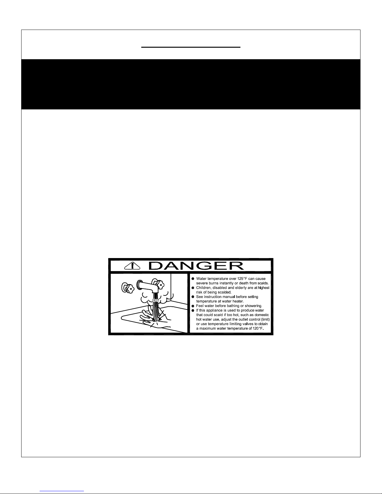
IMPORTANT SAFETY NOTE
It takes only 5 seconds of skin contact with 140°F water to cause a
second degree burn! You must protect against high water temperatures at all
lavatories, tubs, showers and other points of hot water contact.
Accidental scalding from high water temperatures is a greater
risk in some types of installations. Some examples are:
HOMES FOR THE MENTALLY HANDICAPPED
HOMES FOR THE PHYSICALLY HANDICAPPED
HOSPITALS AND NURSING HOMES
ELDER CARE FACILITIES AND REST HOMES
ORPHANAGES AND CHILD CARE FACILITIES
OTHER INSTALLATIONS - WHERE RESPONSE TO CONTACT WITH HOT
WATER MAY BE SLOWER OR WHERE THE DANGER OF HOT WATER
CONTACT IS GREATER
Thermostatically controlled mixing valves must be used in the
design of the potable hot water system.
Potable hot water should be tempered to no more than
110°F when used for bathing or other personal uses.
Good engineering practice mandates the use of thermostatically controlled
mixing valves set at 120°F or less to keep the delivered water temperature
below scalding temperatures.
5
PV500-50 08/14
MAXIM 3® WATER HEATER
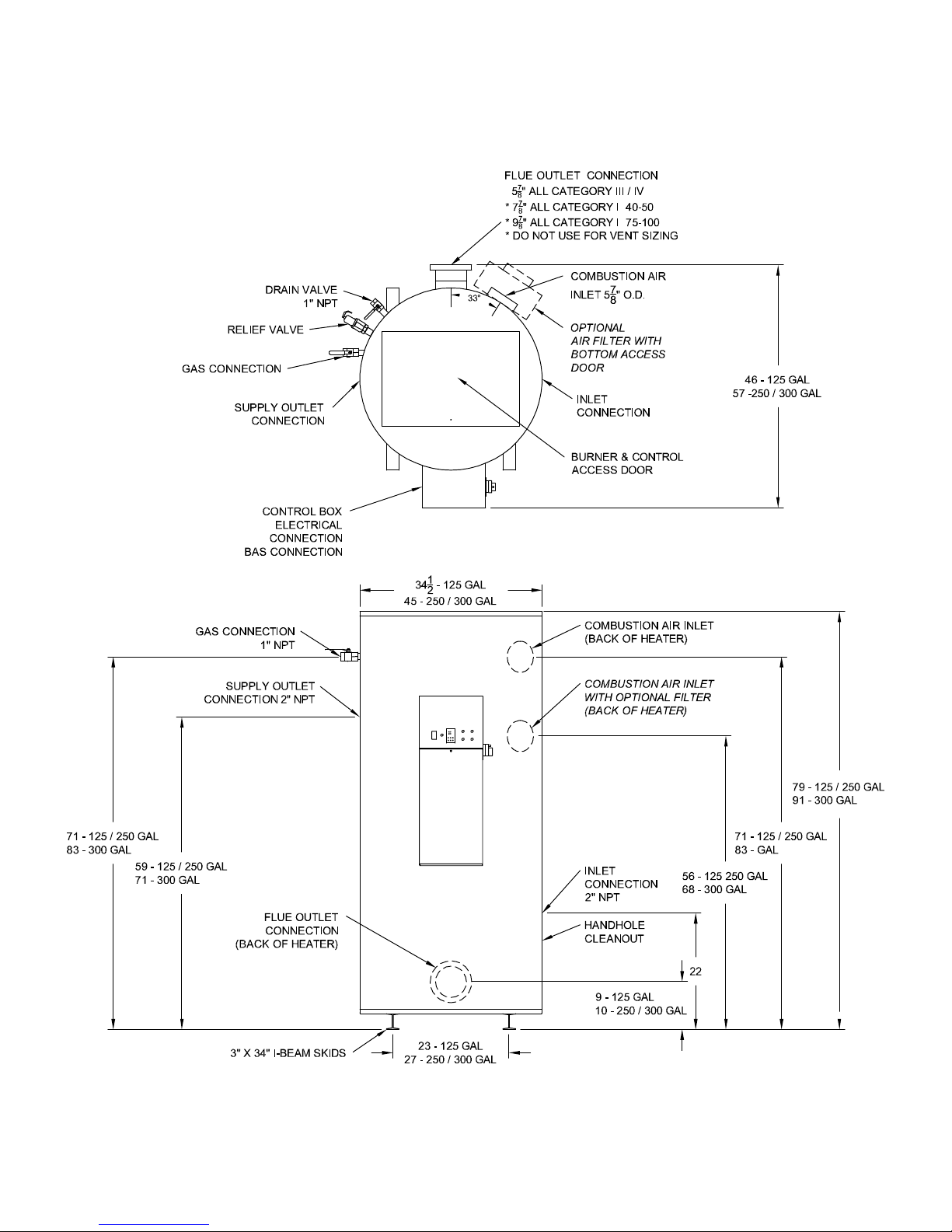
2 PRODUCT DESCRIPTION Component, Controls and Connection Locations
(Locations and Connections May Vary)
6
PV500-50 08/14

MAXIM 3® WATER HEATER
3 WATER HEATER INSTALLATION
3.1 Checking Equipment Before You Install
Inspect the unit completely upon receipt from the freight carrier before signing the bill of lading. Inspect the appliance
and all accompanying parts for signs of impact or mishandling. Verify the total number of pieces shown on packing
slips with those actually received. Contact the freight carrier immediately if any damage or shortage is detected.
3.2 Codes
The equipment must be installed in accordance with those installation regulations in force in the local area where the
installation is to be made. Authorities having jurisdiction must be consulted before installation is made. In the
absence of such requirements, the installation shall be in accordance with the instructions in this manual, appliance
markings and supplemental instructions and in compliance with the latest edition of the National Fuel Gas Code,
ANSI Z223.1. Where required by the Canadian authority having jurisdiction, the equipment must be installed in
accordance with the latest edition of the Installation Code for Gas Burner Appliances and Equipment CAN/CSA
B149.1 and/or B149.2 and applicable Provincial Regulations. All appliances conform to the latest edition of the
ASME Boiler and Pressure Vessel Code, Section IV, Part HLW.
3.3 Electrical Requirements
See appliance rating decal for electrical service requirements. The appliance must be electrically supplied and
grounded in accordance with the requirements of the authority having jurisdiction or in the absence of such
requirements, with the latest edition of the National Electrical Code ANSI/NFPA No. 70. In Canada, the electrical
service must conform to local electrical codes and/or CSA C22.1, Canadian Electrical Code, Part 1.
− All wiring between the unit and field installed devices must be made with type T copper wire.
− Line voltage wire exterior to the appliance must be enclosed in approved conduit or approved metal clad cable.
− To avoid serious damage, DO NOT energize the unit until the system and appliance is full of water.
3.4 Handling and Location
WARNING: Use industry standard safe rigging methods, such as including the use straps and spreader bars
and lifting from the water heater base skid assembly, when attempting to lift or move this product. Failure to
follow industry safe rigging methods could result in property damage, serious injury or death.
1. Check the data decal on the appliance. Be sure the electrical, water, oil, or gas supply is adequate for the
installation.
2. Carefully remove all shipping supports and bracing.
3. These units are suitable for indoor installation only.
4. Locate the unit so that if water connections should leak, water damage will not occur. When such locations
are unavoidable, install a suitable drain pan, and plumb pan to ensure adequate drainage in the event of a
leak. Under no circumstances is the manufacturer responsible for water damage in connection with this unit,
or any of its components. The manufacturer’s warranty does not cover water damage.
5. Protect associated electrical components and electrical connections from water (dripping, spraying, rain,
etc.) during appliance operation and service.
6. Place the appliance on a level, non-combustible floor. Concrete over wood is not considered noncombustible.
7. Do not install on carpet or other combustible floor coverings. If installation over a combustible floor is required,
follow these guidelines:
− Use a base of hollow clay tile or concrete blocks from 8" to 12" thick and extending 24" beyond the sides.
− Place the blocks in line so that the holes line up horizontally to provide a clear passage through the blocks.
− Install 1/2” fireproof millboard with a 20-gage sheet metal cover over the block base.
− Center the unit on the base. Also follow this procedure if electrical conduit runs through the floor, and
beneath the appliance. A field-installed base must meet all local fire and safety code requirements.
7
PV500-50 08/14
MAXIM 3® WATER HEATER
3.5 Service Clearances
Allow sufficient space to provide adequate clearances on all sides for service and inspection. At least 24” above the
water heater is required for filter replacement (if equipped) and burner/gas control service, 18” at left and right sides
of the appliance. Optional equipment may increase the clearance requirements. Allow sufficient space for installing
and servicing connections such as water, gas, vent, combustion air, electrical, pump and other auxiliary equipment.
3.6 Clearances To Combustible Surfaces
Minimum 1” clearance must be provided from any vent surface to adjacent combustible material. The minimum
clearances to unprotected combustible material are 24” be provided at the front, 8” be provided at the rear and 8” at
top, left and right sides of the appliance.
4 GENERAL PIPING GUIDELINES
4.1 Inlet and Outlet Connections
1. Use only non-ferrous water piping and fittings. Do not use galvanized pipe or fittings. Use of ferrous or
galvanized pipe or fittings can cause rust to form.
2. Install shut-off valves and unions on the inlet and outlet water piping for servicing. Use caution when
threading pipe nipples into tank connections to prevent cross threading, or over-tightening. Always use a
back-up wrench on tank nipples when tightening unions, valves, etc.
3. Insulate hot water and return circulation lines. Insulate cold water supply lines if subject to freezing during
shutdown periods. IMPORTANT: Do not use the plumbing connected to the appliance as a ground for
welding or any other purpose.
4. Pipe the drain valve to a suitable open drain.
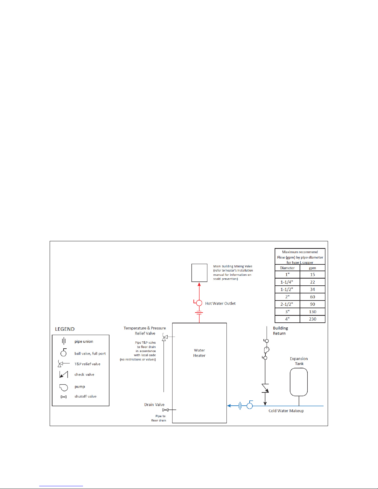
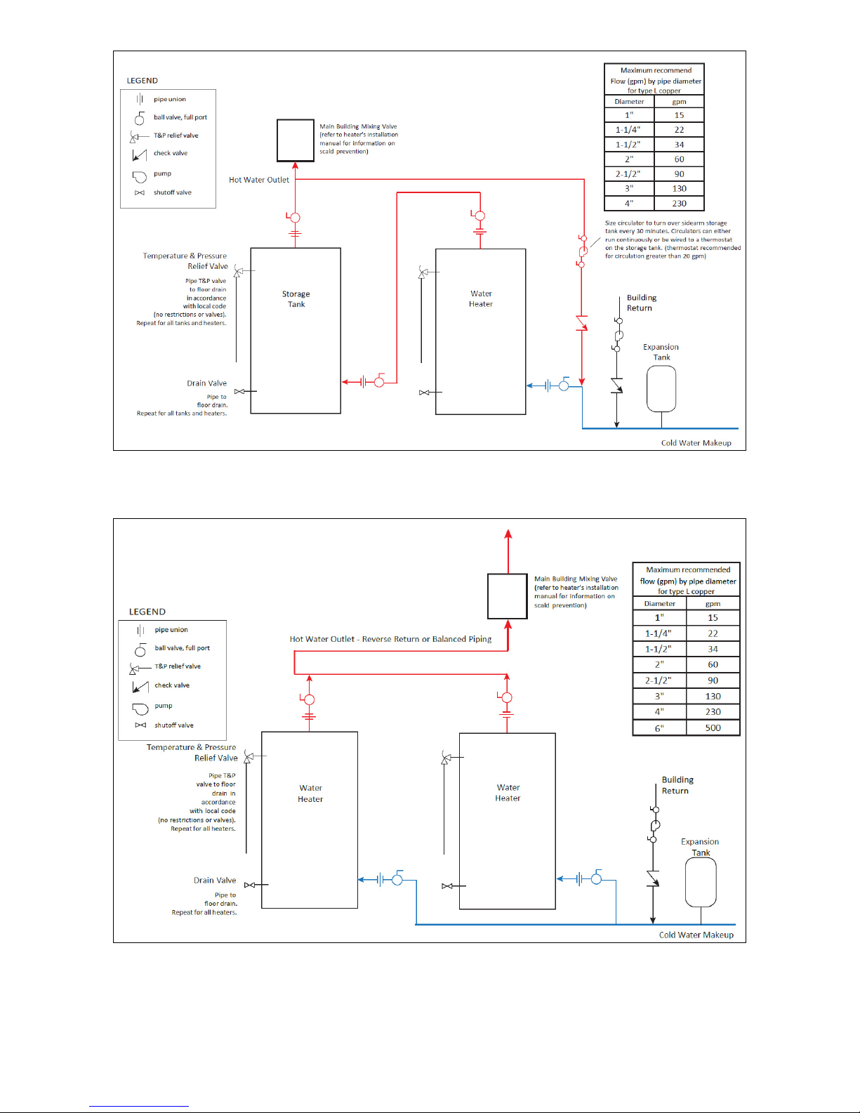
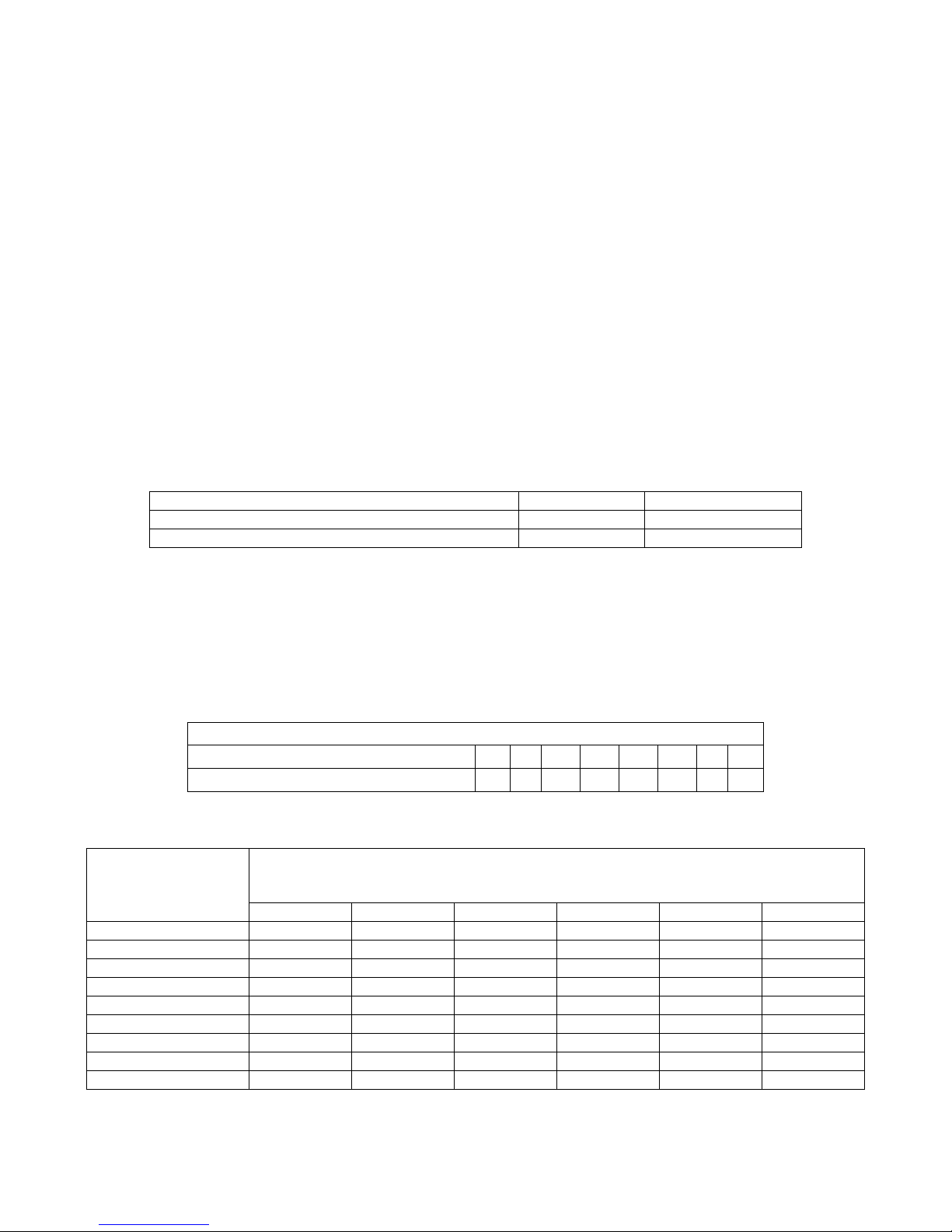
4.2 Building Return Piping
To maximize water heater efficiency, connect the building return (≈ 5 gpm) to the inlet piping as shown below.
Single Water Heater – One Hot Outlet Temperature
WATER HEATER PIPING GUIDELINE
8
PV500-50 08/14
MAXIM 3® WATER HEATER
WATER HEATER PIPING GUIDELINE
One Water Heater – One Sidearm Storage Tank
Two Water Heaters – Single Hot Outlet Temperature
WATER HEATER PIPING GUIDELINE
9
PV500-50 08/14
MAXIM 3® WATER HEATER
5 GAS SUPPLY AND PIPING
Verify that the type of gas specified on rating plate is supplied to the unit. This unit is orificed for operation up to 2000
feet altitude. Appliance Btuh output derates 4% per 1000 feet elevation above sea level. Consult Factory for
installations above 2000 feet elevation.
5.1 Gas Train and Controls Certification
NOTE: The gas train and controls assembly provided on this unit have been tested under the applicable American
National Standard to comply with safety and performance criteria such as proper ignition, combustion and safety
shutdown operation.
5.2 Gas Control Train
All models include gas control trains with the following components: main manual shutoff valve, two safety shutoff
valves, proportionator regulator and a final manual valve with the manifold pressure tap on the side of the valve.
These components may be separate or two or more may be combined in a common housing.
CAUTION: Do not adjust or remove any screws or bolts on gas train control components which are sealed with a red
or blue colored compound. Doing so will void all approvals and warranties.
5.3 Inlet Pressure
Measure at the inlet pressure tap located at the main gas cock. The inlet pressure must remain within the minimum
and maximum values while the unit is at rest and while the unit is operating at maximum firing rate.
Maximum Static Pressure (Inches-Water Column) 14" 14"
Minimum Flow Pressure (Inches-Water Column) 4.5" 11"
INLET PRESSURE NAT. GAS LP
5.4 Manifold Pressure
Measure at the pressure tap located downstream side of the manual valve closest to the burner. The rated manifold
pressure appears on the product data label located near the front of the appliance.
5.5 Gas Piping Size
Use the values in “Convert Fittings To Equivalent Straight Pipe” to add the equivalent straight pipe for each elbow or
tee to obtain the total distance from the meter.
Use this corrected total distance from the meter for determining the suggested pipe size in the “Single Unit
Installation Suggested Gas Pipe Size” table.
Equivalent Feet
From Meter
*Multiplier for Propane: 1.57
**Multiplier for alternate pressure drops: 0.3" W.C. 0.77; 1.0" W.C. 1.41; 2.0" W.C. 2.00; and 4.0" W.C. 2.82.
Equivalent Length of Straight Pipe (feet) 2' 2' 3' 4' 5' 10' 14' 20'
25 860 1320 2475 3900 7000 40 660 990 1900 3000 5300 60 - 810 1520 2400 4300 -
80 - 690 1300 2050 3700 100 - 620 1150 1850 3250 6700
125 - - 1020 1650 2950 6000
150 - - 950 1500 2650 5500
175 - - 850 1370 2450 5000
200 - - 800 1280 2280 4600
CONVERT FITTINGS TO EQUIVALENT STRAIGHT PIPE
Diameter Fitting (inches) ¾" 1" 1¼" 1½" 2" 3" 4" 5"
SINGLE UNIT INSTALLATION SUGGESTED PIPE SIZE
Maximum Capacity for Natural Gas*
MBTU/HR Based on 0.5" W.C. Pressure Drop**
1-1/4" 1-1/2" 2" 2½" 3" 4"
10
PV500-50 08/14
MAXIM 3® WATER HEATER
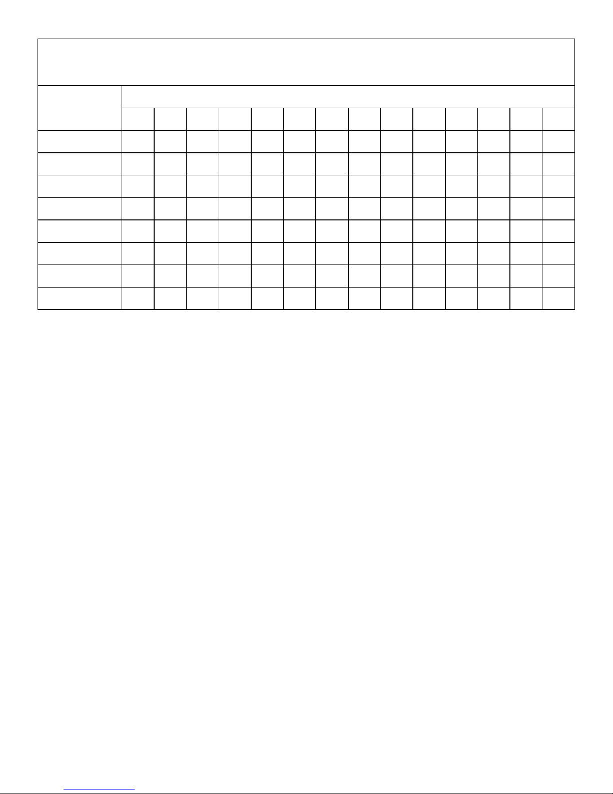
MULTIPLE UNIT INSTALLATIONS GAS PIPING SIZE CHART
Maximum Capacity of Pipe in Thousands of BTU’s per hour for gas pressures of 14 Inches Water Column (0.5
PSIG) or less and a pressure drop of 0.05 Inch Water Column (Based on NAT GAS, 1025BTU’s per Cubic
Foot of Gas and 0.60 Specific Gravity).
Nominal Iron
Length of Pipe in Straight Feet
Pipe Size,
Inches
3/4
1
1 1/4
1 1/2
2
2 1/2
3
4
10 20 30 40 50 60 70 80 90 100 125 150 175 200
369 256 205 174 155 141 128 121 113 106 95 86 79 74
697 477 384 328 292 267 246 256 210 200 179 164 49 138
1400 974 789 677 595 543 502 472 441 410 369 333 308 287
2150 1500 1210 1020 923 830 769 707 666 636 564 513 472 441
4100 2820 2260 1950 1720 1560 1440 1330 1250 1180 1100 974 871 820
6460 4460 3610 3100 2720 2460 2310 2100 2000 1900 1700 1540 1400 1300
11200 7900 6400 5400 4870 4410 4000 3800 3540 3300 3000 2720 2500 2340
23500 16100 13100 11100 10000 9000 8300 7690 7380 6870 6150 5640 5130 4720
5.6 Appliance Isolation during Gas Supply Piping Pressure Test
1. The appliance and its provided manual shutoff valve must be disconnected from the gas supply piping system
during any pressure testing of that system at test pressures in excess of ½ PSI (3.5 kPa).
2. The appliance must be isolated from the gas supply piping system by closing its individual manual shutoff valve
during any pressure testing of the gas supply piping system at test pressures equal to or less than ½ PSI (3.5
kPa).
3. The appliance and its gas connection must be leak-tested before placing it in operation.
5.7 Gas Connection
1. Safe operation of unit requires adequate gas supply with the required static and dynamic (flow) pressures. Actual
piping selection depends on many variables that must be carefully considered by the gas piping system
designer.
2. Do not select gas pipe sizes based only on the supplied tables. These tables are for use by the gas piping
system designer as a reference in checking pipe size selections.
3. Gas pipe size may be larger than heater connection.
4. Installation of a union is suggested for ease of service.
5. Install a manual main gas shutoff valve, outside of the appliance gas connection and before the appliance
provided appliance manual shutoff gas valve, when Codes require.
6. The gas system installer should clearly identify the emergency shut-off device.
7. A sediment trap (drip leg) MUST be provided in the inlet of the gas connection to the unit.
8. The code compliant vent limiters are designed and must respond to pressure changes in the installation
environment, as opposed to outdoor pressure. For proper operation, do not connect to outdoor atmosphere.
11
PV500-50 08/14
MAXIM 3® WATER HEATER
6 COMBUSTION AND VENTILATION AIR
Provisions for adequate combustion and ventilation air to the mechanical room must be in accordance with Section
5.3 “Air for Combustion and Ventilation” of the latest edition of the National Fuel Gas Code, ANSI Z223.1 and/or
CAN/CSA B149, Installation Codes or applicable provisions of the local building codes.
6.1 Equipment Located In Confined Spaces
Equipment located in confined spaces requires two openings installed within 12” (30.5 cm) from the top and bottom
of the room to assure adequate combustion air and proper ventilation. The total input of all gas utilization equipment
installed in the room must be used to determine the required minimum air volume needed for combustion, ventilation
and dilution of flue gasses.
• All Air From Outdoors:
Each opening requires a minimum free area of 1 square inch
the outdoors or communicating to the outdoors through vertical ducts.
Each opening requires a minimum free area of 1 square inch
outdoors through horizontal ducts.
All Air From Inside The Building:
Each opening requires a minimum free area of 1 square inch
inches (0.06 m
2)
.
Combination Of Air From The Indoors And From The Outdoors:
per 4000 Btu/hr input if directly communicating with
per 2000 Btu/hr input if communicating with the
per 1000 Btu/hr input, but not less than 100 square
Refer to National Fuel Gas Code, ANSI Z223.1 and/or CAN/CSA B149, Installation Codes or applicable
provisions of the local building codes.
NOTE: This unit may be installed with a remote air intake system which uses a make-up air duct to draw combustion
air directly from outdoors.
WARNING: Adequate clean combustion air must be provided to the appliance. Under no circumstances
should the appliance ever be under a negative pressure. Particular care should be taken when exhaust fans,
compressors, air handling units, etc. may rob air from the appliance. The combustion air supply must be
completely free of any chemical or fumes, which may be corrosive to the appliance. Some common chemical
fumes to avoid are fluorocarbons and other halogenated compounds, most commonly present as
refrigerants or solvents, such as Freon, trichloroethylene, perchlorethylene, chlorine, etc. These chemicals,
when in contact with the equipment or when burned, form acids which quickly attack the tubes, flue
collector, stack and other appliance and auxiliary equipment. The result of inadequate clean combustion air
or negative pressure can be premature unwarranted product failure or unsafe operation producing carbon
monoxide that could escape into the building. Exposure to carbon monoxide can lead to injury or death.
6.2 Maximum Allowed Remote Combustion Air Inlet Length (Equivalent Length)
A vertical or horizontal remote air inlet system can be connected to this appliance without modification. The
maximum length of field supplied single wall pipe, such as galvanized ventilation pipe, is shown in the chart below
titled Maximum Air Inlet Duct Equivalent Length. Use metal tape or RTV sealant to seal each pipe joint.
Maximum Air Inlet Duct Equivalent Length
Duct Size 6” Duct 7” Duct 8” Duct 9” Duct
Max Equivalent Length
100 feet 130 feet 250 feet 450 feet
To determine the maximum straight length of duct allowed, use the Duct Fitting Equivalent Length chart below to find
the total equivalent length for all duct fittings in your combustion air system. Then subtract this number of feet from
the total equivalent length allowed in Maximum Air Inlet Duct Equivalent Length chart above. The sum of this
calculation is the maximum length of straight duct allowed. If a longer length is required, repeat the calculation using
a larger duct size. No additional deduction is required for the addition of the duct system terminal.
12
PV500-50 08/14
 Loading...