

XTERNA Module
Issue 2 (01 October 2018)
www.pvelectronics.co.uk
- 1 -
Assembly Instructions
And
User Guide
XTERNA
Module

XTERNA Module
Issue 2 (01 October 2018)
www.pvelectronics.co.uk
- 2 -
REVISION HISTORY
Issue
Number
Date Reason for Issue
2 01 October 2018 New position for D1
1 20 April 2018 New document

XTERNA Module
Issue 2 (01 October 2018)
www.pvelectronics.co.uk
- 3 -
1. INTRODUCTION
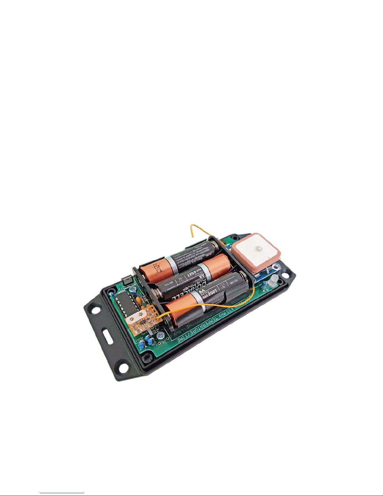
1.1 About the XTERNA Module
XTERNA is our new concept for synchronising time and capturing
outdoor temperature for display on our clock and thermometer kits.
Driven by a PIC microcontroller with advanced low power modes, the
XTERNA captures time from GPS satellites every 6 to 24 hours, and
stores in an on-board Temperature Controlled Crystal Oscillator
(TCXO). Further, the device captures outdoor temperature every 10
minutes from an on-board DS18B20 digital temperature sensor.
Every 10 minutes XTERNA transmits the time and temperature data,
which can be received by our XTERNA compatible clocks.
Additional data is transmitted such as battery voltage and GPS fix
time.
Supplied as a complete hobby kit of parts (For shipping reasons,
batteries are not included), the kit takes approx 30-40 minutes to
comfortably assemble. The TCXO IC is pre-soldered, so there is no
fiddly SMD soldering to worry about.
Naturally, XTERNA is sealed against rain ingress. Battery life is
estimated between 6 to 12 months. We recommend high quality
branded batteries for the longest operation between battery
changes.
The module should be placed outdoors, but as close as possible to
the indoor clock or thermometer. Avoid direct sunlight and shelter
from rain as far as possible.
1.2 Specification
Working Temperature Range: -40 °C to +60 °C. (-40 °F to
+140 °F)
Typical Reception Range: 10 to 30 Metres (30 to 100 ft).

XTERNA Module
Issue 2 (01 October 2018)
www.pvelectronics.co.uk
- 4 -
2. TOOLS AND EQUIPMENT REQUIRED
2.1 Tools required to assemble the PCB.
The following tools will be required to assemble the PCB:
- Soldering iron with a small tip (1-2 mm).
- Wire cutters to trim the excess component leads after soldering.
(Tip: A small pair of nail clippers works very well for this
function).
- Wire strippers (Tip: A small pair of scissors is quite suitable).
- Multimeter for identifying the resistors.
- Screwdrivers.
2.2 Materials you will need.
Solder – lead / tin solder is highly recommended. USE LEAD/ TIN
SOLDER!.
Lead free solder, as now required to be used in commercial
products in Europe, has a much higher melting point and can be
very hard to work with.
Desoldering wick (braid) can be useful if you accidentally create
solder bridges between adjacent solder joints.
Decorator’s masking tape.
2.3 Other items you will need.
The XTERNA module is powered by 3 X AA Batteries. We
recommend high quality branded batteries for the longest service
life between battery changes.
XTERNA Module
Issue 2 (01 October 2018)
www.pvelectronics.co.uk
- 5 -
3. LIST OF COMPONENTS
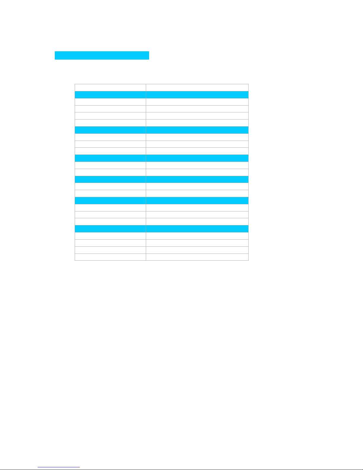
3.1 Table of Electronic Components
PCB Designation Part Description
Resistors
R1, R2 10 KΩ, ¼ Watt
R4 1 KΩ, ¼ Watt
R5 390 KΩ, ¼ Watt
R7 – R9 10 KΩ, ¼ Watt
Capacitors
C1 Not Installed
C2, C3 1uF Ceramic
R3 1uF Ceramic
Transistors
T1 FQU13N10L
T2 2N7000
Diodes
D1 1N4148
LED1 RGB LED 5mm Common Cathode
Integrated Circuits
IC1 PIC16F1825
IC2 DS18B20
IC5 PCF2129AT (Pre-soldered)
Miscellaneous
MOD1 4 way 0.1” female header
MOD3 4 X Turned Pin Sockets
IC1 Socket 14 Way narrow IC socket for IC1
BH-331P 3 X AA Battery Holder

XTERNA Module
Issue 2 (01 October 2018)
www.pvelectronics.co.uk
- 6 -
3.2 Parts list / Packing Sheet
Part Description Quantity
Resistors
1 KΩ, ¼ Watt 1
10 KΩ, ¼ Watt 5
390 KΩ, ¼ Watt 1
Capacitors
1 uF, Ceramic 3
Transistors
2N7000 1
FQU13N10L 1
Diodes
RGB LED 5mm Common Cathode 1
1N4148 1
Integrated Circuits
PIC16F1825 1
DS18B20 1
Miscellaneous
4 way 0.1” female header 1
Turned Pin Sockets 4
14 Way narrow IC socket for IC2 1
M3 X 4mm screw 2
M3 X 6mm Female / Female Spacer 1
433 MHz Tx Module 1
Self tapping screw 5
20cm cable for Antenna 1
4 X 0.1” turned pin header for GPS 1
Double sided foam square 1
Neo-6M GPS Module 1
3 X AA Battery Holder 1
Hammond Case with screws 1
PCB with pre-soldered IC5 1
It is recommended that the kit is checked against the list above, to
ensure all parts are present before commencing assembly. Don’t be
alarmed if there are some extra components, as some component
bags are shared between different kit types.
The resistors used in the kit are 1% tolerance metal film. They are
marked with 4 coloured bands to identify the value. However it is
sometimes unclear in which direction the bands should be read.
Therefore, we recommend that the resistors be identified with a
multimeter.
XTERNA Module
Issue 2 (01 October 2018)
www.pvelectronics.co.uk
- 7 -
4. ASSEMBLY OF THE PCB
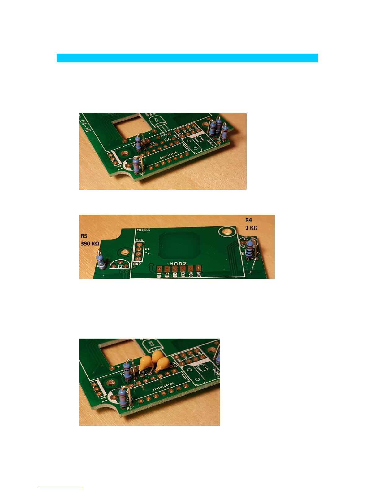
4.1 R1, R2, R7, R8, R9 (10 KΩ)
Bend one lead of each resistor sharply – no large curved bends
which could touch other components – and solder the five resistors
as shown.
4.2 R5 (390 KΩ) , R4 (1 KΩ)
4.3 C2, C3, R3 (1uF)
Note that a capacitor is soldered at the R3 position. You will need
to form the leads of this capacitor to better fit the pad spacing.
These capacitors are not polarized, so the orientation does not
matter.

XTERNA Module
Issue 2 (01 October 2018)
www.pvelectronics.co.uk
- 8 -
4.4 Socket for IC1
Ensure the small notch is oriented as shown. However if after you
solder the part you realise the notch is at the wrong end, DON’T try
to desolder it! Actually, so long as the IC has the correct
orientation, the socket does not really matter.

XTERNA Module
Issue 2 (01 October 2018)
www.pvelectronics.co.uk
- 9 -
4.5 MOD1 (4 X 0.1” Female Header) and T1 (FQU13N10L)
These parts are arrowed below. Don’t solder T1 too close to the
PCB. Keep it 3-5mm from the PCB.
4.6 D1 (1N4148)
Bend and solder D1 with care that the black band is oriented as per
the photo below. There may be photos in the manual that show it
soldered at the ‘D1’ postion on the component side. Disregard this.

XTERNA Module
Issue 2 (01 October 2018)
www.pvelectronics.co.uk
- 10 -
4.7 Prepare the GPS Module
First, apply the self adhesive foam pad to the back of the antenna,
then stick onto the plain PCB side of the GPS, oriented so that the
antenna cable can pass through the hole intended for it.
Now clip the antenna connector into the small matching connector
on the component side of the GPS module. It helps to press with a
hard surface, such as a small block of metal.
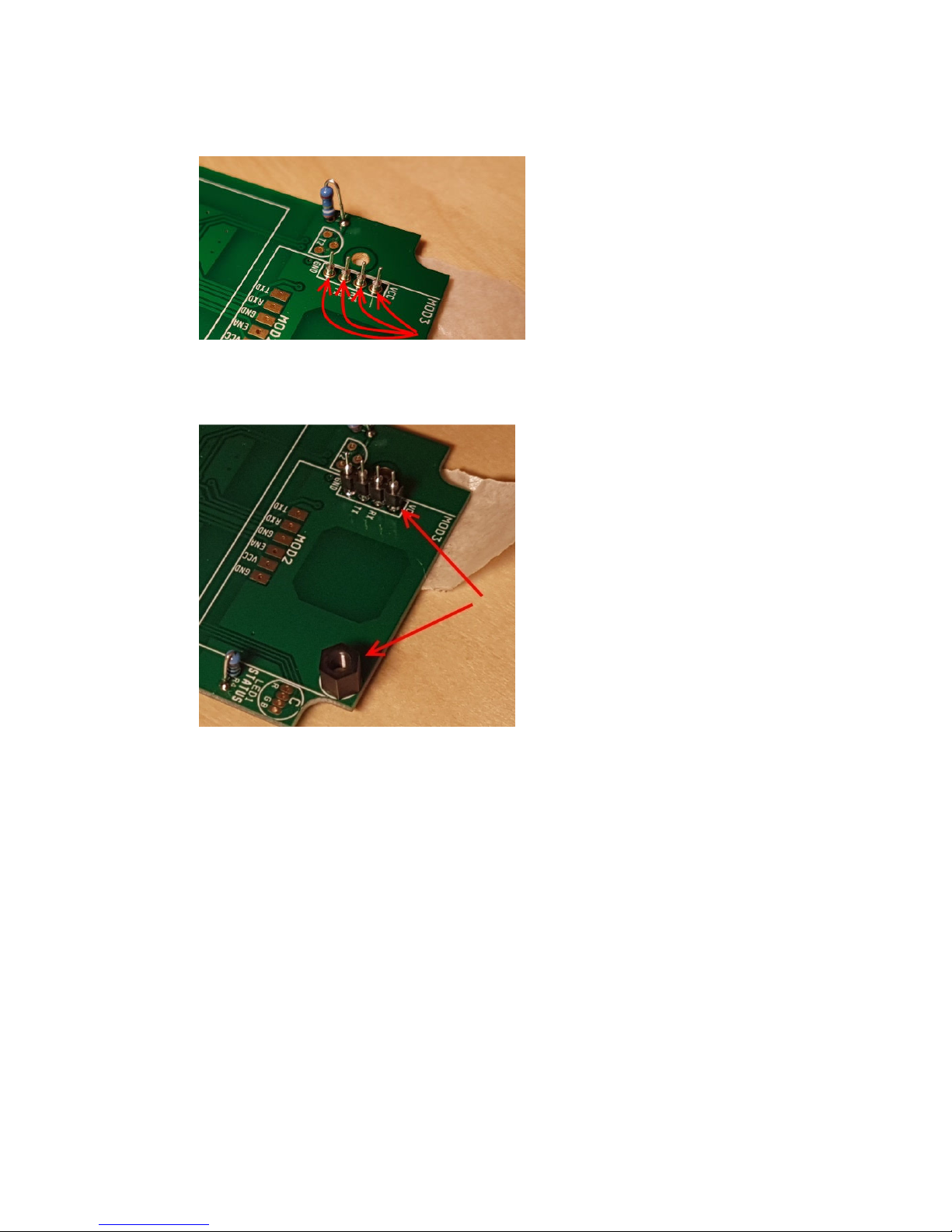
4.8 Attaching the GPS.
From the SOLDER side of the PCB, insert the four socket
receptacles and secure with decorator’s masking tape.
Flip over the PCB and solder the four sockets with minimal solder,
as shown below. As soon as you see the solder flow around the
annulus, you can withdraw the solder and iron.
XTERNA Module
Issue 2 (01 October 2018)
www.pvelectronics.co.uk
- 11 -
Now plug the four way header strip over the pins and also screw on
the 6mm spacer as shown below, using a M3 X 4mm plastic screw.
Now place on the GPS assembly, over the four connector pins and
screw in place with the other M3 X 4mm plastic screw, then solder
the four pins to the GPS. Keep the GPS level and pushed down as
you solder.

XTERNA Module
Issue 2 (01 October 2018)
www.pvelectronics.co.uk
- 12 -
Once the pins have been soldered, unscrew the top plastic screw
and withdraw the GPS. Don’t forget to put it back again later!
4.9 LED1 (5mm RGB LED) and T2 (2N7000)
The longest lead of the LED goes in the marked hole. Take care
you orient correctly.

XTERNA Module
Issue 2 (01 October 2018)
www.pvelectronics.co.uk
- 13 -
4.10 IC2 (DS18B20)
Insert just a few millimetres, then bend over as shown and solder.
The flat, engraved front surface should be showing.
4.11 AA Battery Holder
Insert the battery holder, and first screw it to the PCB with two
self-tapping screws. Then solder the two wires.

XTERNA Module
Issue 2 (01 October 2018)
www.pvelectronics.co.uk
- 14 -
4.12 Transmitter Module
Cut 17cm of the cable supplied, strip off 3mm of the insulation
from one end and tin the wires. Then attach to the end pad of the
Transmitter module as shown.
4.13 Final Assembly
Re-attach the GPS module, not forgetting the M3 X 4mm screw.
Orient the notch on the IC with the corresponding marking on the
socket and push into the socket. Push in the Transmitter module,
with the three pins in the three holes closest to IC1. Feed the
antenna wire around the battery holder. Finally screw the PCB to
the base of the case with the remaining three self-tapping screws.

XTERNA Module
Issue 2 (01 October 2018)
www.pvelectronics.co.uk
- 15 -
5. USING XTERNA
5.1 CONFIGURING YOUR CLOCK OR THERMOMETER
Usually, the clock or thermometer will be pre-configured to receive
the 433MHz broadcasts. All you need to do is set the time zone of
any clock for your offset from UTC. (Usually parameters 14,15,16)
5.2 POWERING UP FOR THE FIRST TIME
For the first use, configure your clock, and then position the
XTERNA module as close as possible to the clock, but with a good
view of the sky. Insert three NEW, top quality AA batteries. Keep
the top cover open, so you can follow the progress on the RGB
LED, in case of issues.
After inserting the batteries, the module will follow a pattern of
calibration and GPS seek, which can be followed on the RGB LED.
In case of issues, it will be helpful to follow the sequences, and
make notes of the timings. Initially, just follow the LED. Only make
timing notes if you have issues.
5.3 RGB LED SEQUENCE
1. Power up
2. LED off for 5 seconds
3. Start initial GPS seek. Red/Green flashing for up to 120 seconds
4. Hold on Green for 5 seconds = GPS module found
5. LED Off for 5 seconds
6. First GPS calibration. Red/Green flashing for up to 120 seconds
7. LED off for 5 seconds
8. GPS calibration. Red/Green flashing for up to 20 minutes
9. LED off, followed by burst of green flashes (data transmission)

XTERNA Module
Issue 2 (01 October 2018)
www.pvelectronics.co.uk
- 16 -
6. CIRCUIT
 Loading...