

Page 1

Installation Guide
Rooftop Tracker
PVB_IG_071918
pvbooster.com
Page 2
Table of Contents
PV Booster Specifications ............................................................................................... 3
Installation Overview ....................................................................................................... 4
Materials Required .......................................................................................................... 5
Tracker Support Structure ............................................................................................... 6
Tracker Control Unit ...................................................................................................... 10
Tracker Module Clamp .................................................................................................. 12
Solar Components......................................................................................................... 13
Additional ...................................................................................................................... 14
www.pvbooster.com | 2
Page 3

PV Booster Specifications
Tracking
Single Axis, 180° range azimuth
Modules
Compatible with 60 cell and 72 cell panels
Roof Attachment
Mechanical Attachment
Ground Coverage Ratio
Up to 50%
Roof Pitch Tolerance
Up to 10°
Materials
Aluminum, Stainless Steel, Acetyl
Dimensions
715mm W, 1080mm L, 850mm H
Weight
30 lbs. excluding panel and roof attachment
Wind Rate
110 mph (ASCE 7-10 compliant)
Power Consumption
½ Watt
Warranty
10 year limited warranty
Annual Maintenance
<1% additional O&M cost (see O&M Guide)
Roof Material
Compatible with most roof anchoring system
per manufacturer specifications
Grounding & Bonding
Rooftop grounding loop shared with PV string
Certifications
UL 2703 & UL 3703 and CE design
compliant. Certification pending.
www.pvbooster.com | 3
Page 4
Installation Overview
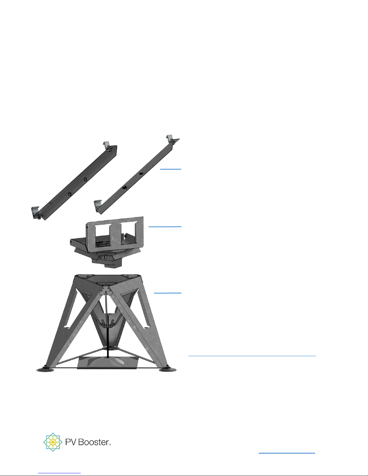
PV Booster Module Clamp
Secures PV panel to tracking structure
Tracker Control Unit
The mechanism that tracks the azimuth of
the sun throughout the day.
Tracker Support Structure
The mechanical attachment which
physically connects each tracker unit to the
roof.
Solar Components
May included Cable, PV Modules,
Inverters, and Power Optimizers
www.pvbooster.com | 4
Page 5

Materials Required
Per PV Booster Unit
EDISUN SUPPLIED
Tracker Support Structure
(3) Tripod Tension Straps
(3) Tripod Feet
(3) Tripod Bolts, Nuts, and Washers
(3) Tripod Anchor Hooks
Tracker Control Unit
(1) PV Booster Actuator
(2) PV Booster Power Cable Grommets
Tracker Module Clamp
(2) Module Support Brackets
(4) Module Support Bracket Bolts and Nuts
(4) Module Support Clamps
CONTRACTOR SUPPLIED
Tracker Support Structure
Mechanical Attachment & Hardware
Mechanical Attachment Membrane/Sealant
Torque Limiter
Tracker Control Unit
Cable Management System
Cable Management Clamp/Interface
Tracker Module Clamp
(None)
(4) Module Support Clamp Bolts and Nuts
Solar Components
(None)
Additional TDB – Project Specific
TBD: Cable Management Support Bracket (for between row cable routing)
TBD: PV Booster Pre-terminated Power Cable (quantity and length TBD)
Solar Components
PV Panel and Cable
PV Optimizer (Best Practice)
Additional Equipment
www.pvbooster.com | 5
Page 6
Tracker Support Structure
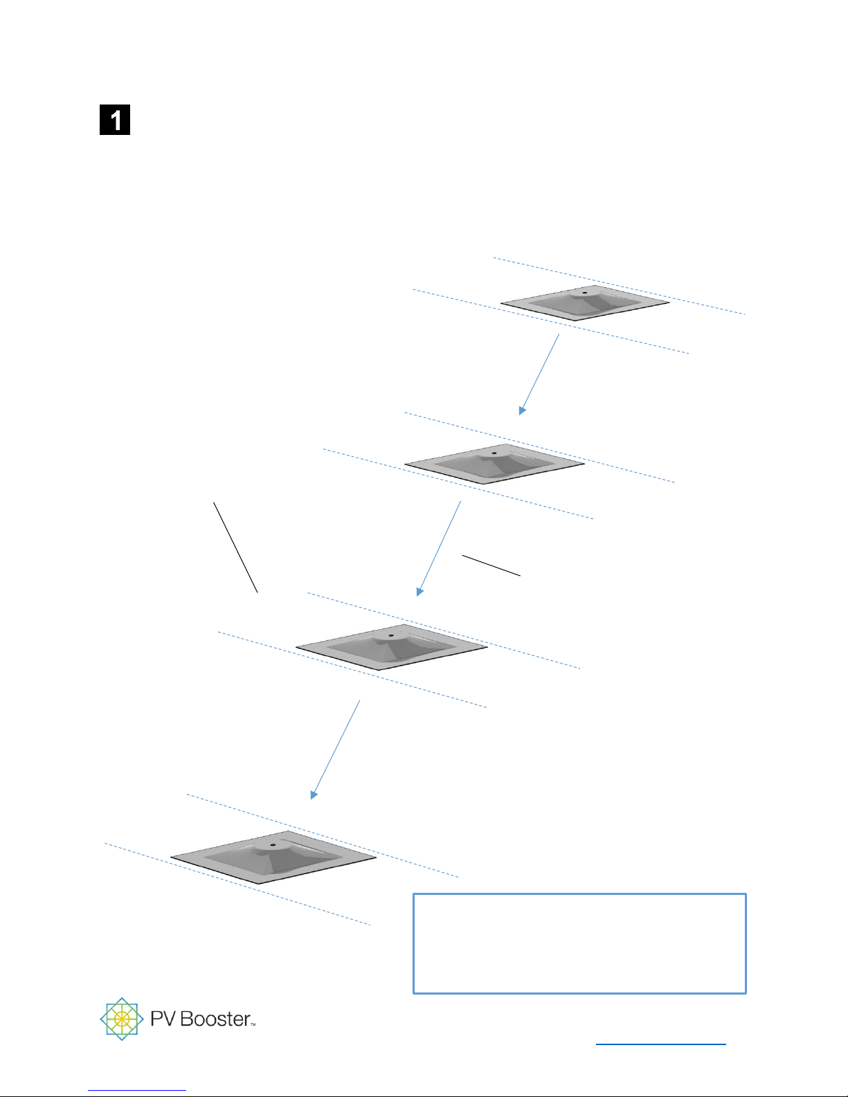
Materials Used In this Step
Mechanical Attachment & Hardware
Mechanical Attachment Membrane/Sealant
Roof support beam
Row path
Mechanical Attachment
Install mechanical attachment per manufacturer specifications on surveyed locations.
www.pvbooster.com | 6
Page 7
Tracker Support Structure
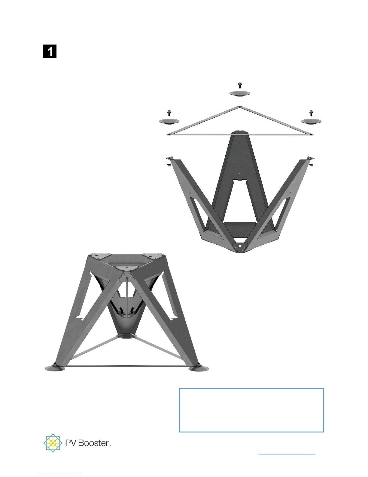
1. Unstack tripod bases and add 3
tensions straps to each leg.
2. Add 3 feet to each leg.
3. Add washer and nut to bolts
and tighten.
Materials Used In this Step
Tripod Tension Straps, Feet, and Fasteners
Tripod & Tripod Anchor Hooks
4. Place anchor hooks on tripod
and connect to mechanical
attachment interface.
Assemble PV Booster Tripod
www.pvbooster.com | 7
Page 8
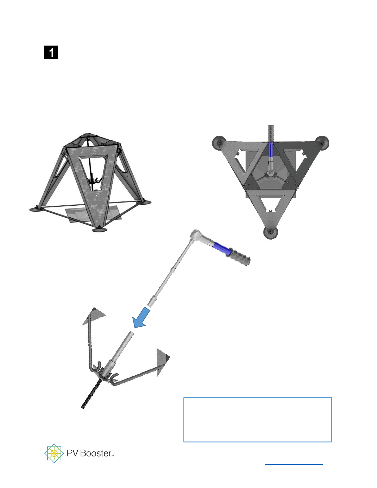
Tracker Support Structure
1. Center tripod above mechanical attachment bolt.
2. Using a torque limiter, connect mechanical
attachment interface to mechanical
attachment hardware and tighten.
Materials Used In this Step
Mechanical Attachment Hardware
Torque Limiter
Install PV Booster Tripod
www.pvbooster.com | 8
Page 9
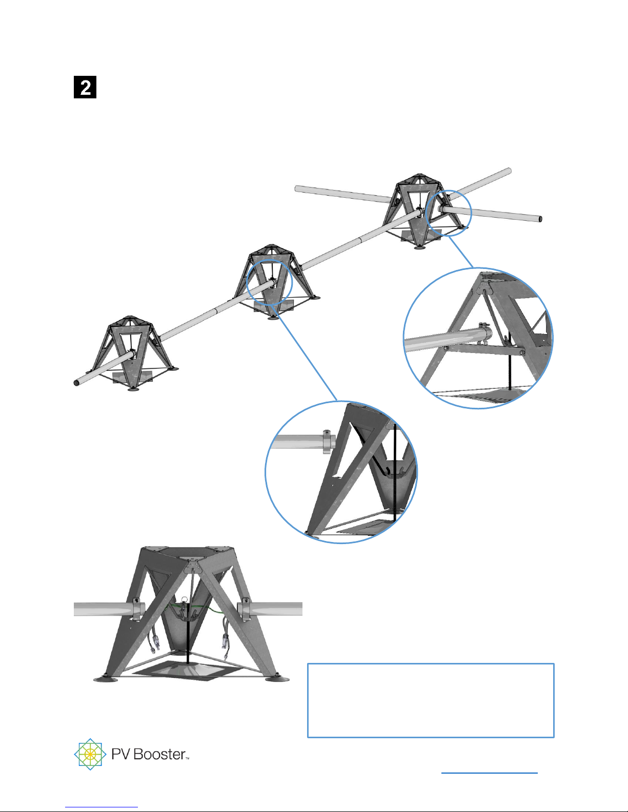
Tracker Control Unit
1. Route preferred cable
management system in
accordance with electrical design
specifications for project.
Materials Used In this Step
Cable Management System & Interface
PV Booster AC Power Cable
2. Pull PV Booster AC Power Cable
3. Attach cable management
to PV Booster with proper
fastener
Optional inter-row
cross brace
Cable Management and PV Booster AC Power Cable
www.pvbooster.com | 9
Page 10
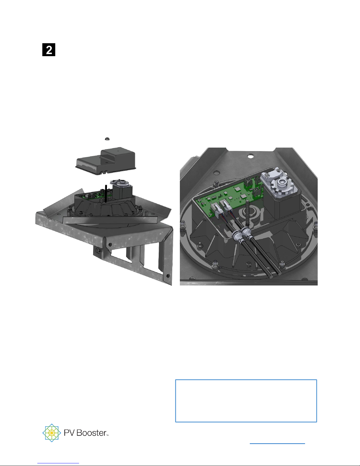
Tracker Control Unit
1. Invert PV Booster Actuator
and Remove Actuator Cover
Materials Used In this Step
PV Booster Actuator
PV Booster Actuator Cable Grommets
2. Land PV Booster AC Power
Cable to Actuator Terminals
Install PV Booster Actuator
www.pvbooster.com | 10
Page 11
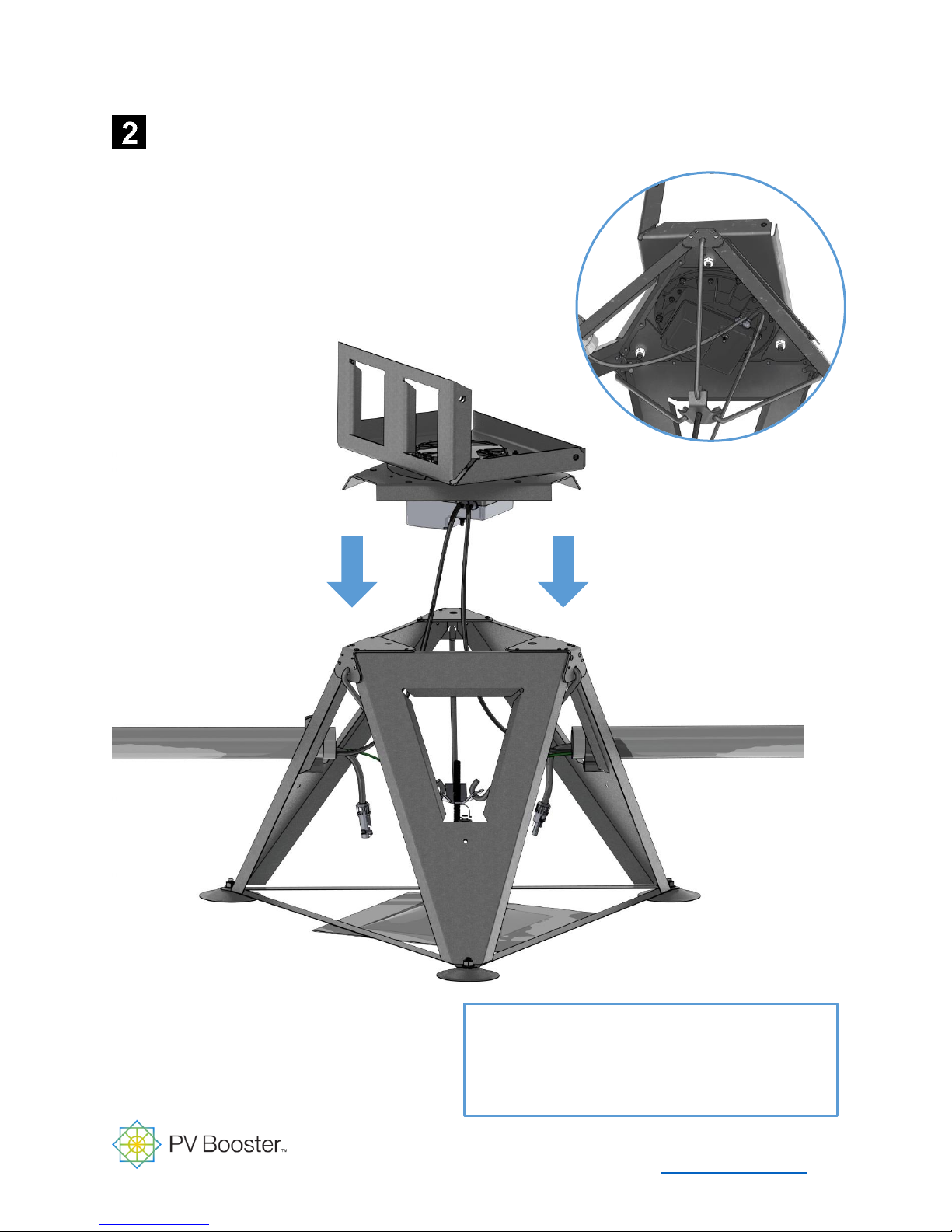
Tracker Control Unit
1. Remove PV Booster Actuator nuts
2. Place PV Booster Actuator including bolts
3. Tighten PV Booster Actuator nuts
Materials Used In this Step
PV Booster Actuator
Install PV Booster Actuator
www.pvbooster.com | 11
Page 12
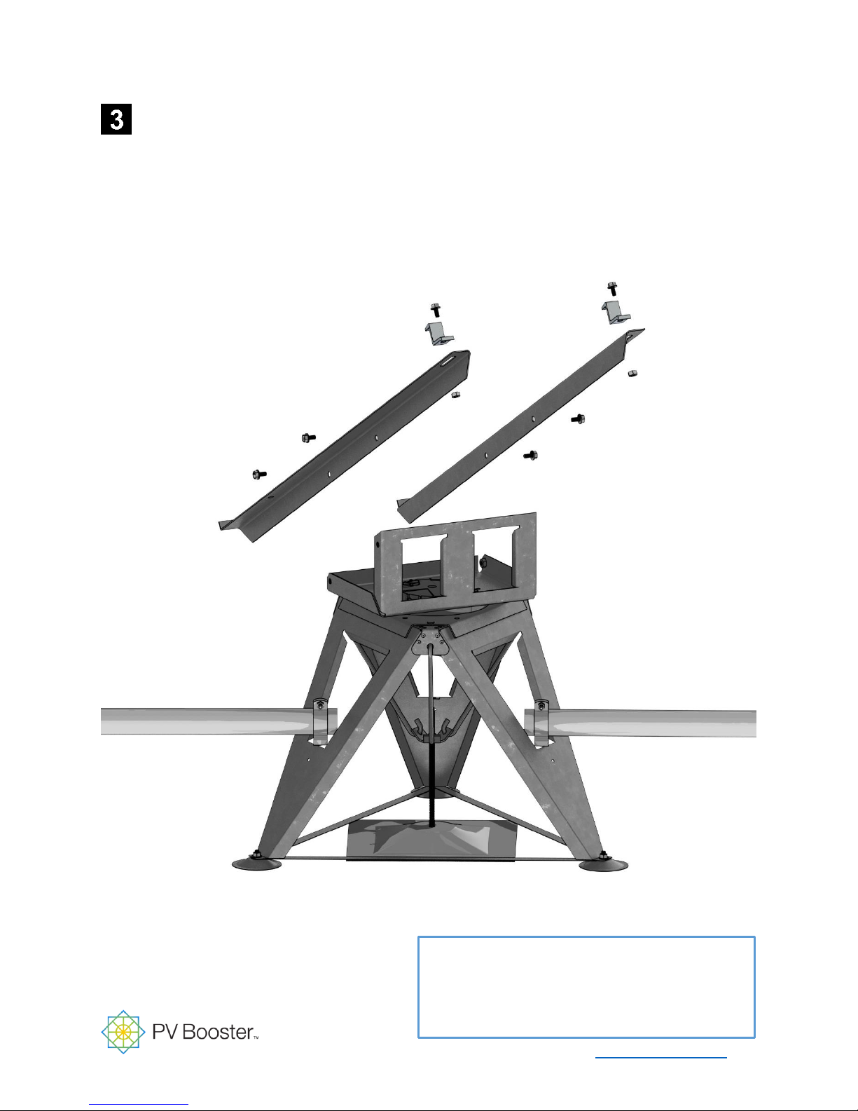
Tracker Module Clamp
1. Attach Module Support Frame to PV Booster Actuator
2. Attach Module Top Clamps to Module Support Frame
Materials Used In this Step
Module Support Brackets and Fasteners
Module Support Clamps and Fasteners
Install PV Booster Module Support Frame
www.pvbooster.com | 12
Page 13
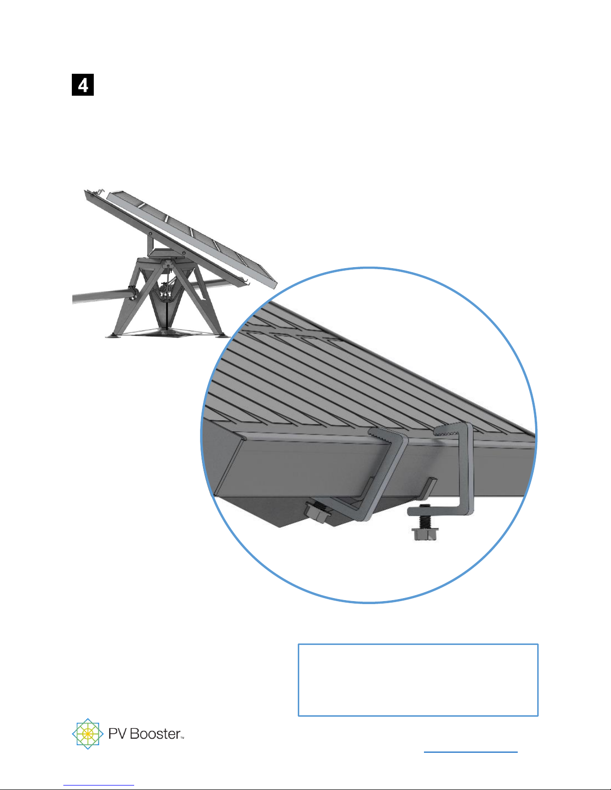
Solar Components
2. Place PV Module to PV Booster Support Frame
1. Attach PV Booster Bottom Clamps
Materials Used In this Step
Module Support Brackets and Fasteners
Module Support Clamps and Fasteners
3. Wire PV Module per Manufacturer Specifications
Install PV Module
www.pvbooster.com | 13
Page 14

Additional Resources
PV Booster website contains the following documents to help you work with PV Booster:
PV Booster Data Sheet
PV Booster Rooftop Case Study
PV Booster Design Guide
PV Booster Installation Guide
PV Booster O&M Guide
PV Booster Warranty
Thank you for your review. Our engineering team is constantly working to improve PV
Booster for installers, clients, and financiers of rooftop solar projects.
Please contact us if you need any assistance to bring rooftop tracking to your client.
www.PVBooster.com
(626) 535-2862
www.pvbooster.com | 14
 Loading...