


Using The Electronic Manual
Requirements
The following is a list of system requirements for the electronic manual:
Pentium Processor
64 MB of RAM
50 MB of Available Hard Drive Space
Windows
CD-ROM Drive
800 x 600 Screen Resolution
AutoCAD® or Volo™ View 2000-129 (Volo™ View is provided on CD)
Adobe
Opening the Manual
To open the electronic manual, insert the manual CD into your CD-ROM drive. The manual startup menu will
appear. If this is the first time the manual has been used, a disclaimer will have to be acknowledged. If your CDROM drive is not configured to Auto Run, open Windows Explorer
Navigation
Navigating the electronic manual can be done by clicking on a topic in the left pane. Several of the topics have
sub-topics which can be accesses by clicking on the [+] symbol to the left of the parent topic. The table of
contents also has links to specific areas of the manual. To search for a specific topic, use the find function by
keying ‘CTRL+F’.
®
98 SE, Millenium, NT, 2000, or XP Operating System
®
Acrobat® or Acrobat® Reader (Acrobat® Reader is provided on CD)
®
and open ‘Startupmenu.exe’.
Viewing Documents
The electronic manual uses external documentation for schematics, custom equipment documentation, etc. To
view these documents, click the link to the specified topic. If the topic is located on an external document, there
will be a button to access these documents. When you click the button, Adobe
®
may display a confirmation
message asking if you want to launch the application used to view the document. Select All, and a list of
available documents on that topic will appear. Click the document you wish to view. To return from an external
document, click on the back arrow for PDF documents. Close the AutoCAD
®
viewer to return from viewing a
schematic. All schematics are in a *.dwg format, and all other external documents are in *.pdf format. A
compatible viewer for each type of document is required to run the electronic manual.
Troubleshooting
If you have a problem with the electronic manual, check the following:
• The electronic manual was started using the ‘Startupmenu.exe’ file.
• The electronic manual disclaimer has been acknowledged.
• There is an AutoCAD
• There is a Portable Document Format compatible viewer installed (PDF Viewer).
• The original directory structure has not changed.
If everything in the above list checks out and you are still having problems with the electronic manual, uninstall
®
Adobe
Acrobat® (or Adobe® Reader), and AutoCAD® (or Volo™ View), then reinstall each.
®
compatible viewer installed.

Disclaimer
CAREFULLY READ ALL OF THE TERMS AND CONDITIONS OF THIS DOCUMENT BEFORE
INSTALLING THIS MEDIA. OPENING OF THIS MEDIA CONSTITUTES ACCEPTANCE OF ALL OF
THE TERMS AND CONDITIONS OF THIS AGREEMENT.
If you do not agree to these terms and conditions, you may return this media and the other components of this
product.
PRECISION VALVE & AUTOMATION, INC. owns the copyright to this media.
Copyright© 1997-2004 Precision Valve & Automation, Inc.
All Rights Reserved.
This document may not, in whole or in part, be copied, photocopied, reproduced, translated, or copied to any
electronic medium or machine-readable form without prior consent in writing to Precision Valve &
Automation, Inc., 15 Solar Drive, Halfmoon, NY 12065.
Limitation of Liability. In no event will Precision Valve & Automation, Inc. be liable for any damages,
including lost profits or any special, indirect, incidental or consequential damages, arising out of this
agreement or the inability to use this media, whether claimed under this agreement or otherwise.
Nondisclosure. The documents in this media, terms, pricing and all information identified as confidential under
this Agreement are considered confidential information (“Confidential Information”). Confidential Information
shall not include information that: a) becomes part of the public domain without breach of this Agreement by
Customer; b) has been published or is generally known to the public at the time of its disclosure to Customer; c)
was at the time of receipt otherwise lawfully known to the Customer; or d) is disclosed with the written approval
of Precision Valve & Automation, Inc. Customer agrees not to make Confidential Information available in any
form to any third party and not to use Confid ential Information for any purpose other than the implementation of
this Agreement. Customer agrees to take all reasonable steps to ensure that Confidential Information is not
disclosed in violation of the terms of this Agreement.
This Agreement shall be governed by the laws of the State of New York and Customer agrees to submit to the
exclusive jurisdiction of New York courts.
Coating and Dispensing
System Manual
- PVA2000
- PVA3000
- PVA2000C
- PVA750
- PVA550
- PVA250
info@pva.net
(518) 371-2684
15 SOLAR DRIVE - HALFMOON, NY 12065
PHONE: (518) 371-2684 - FAX: (518) 371-2684
All Rights Reserved, Copyright (c) 2003 Precision Valve & Automation, Inc.

PVA250
P/N: SNGT1133 S/N: W1948
Singletec, Inc.
TM
Operating Guide
Automated Dispensing System
15 Solar Drive – Halfmoon, NY 12065

Table Of Contents
Configuration
1
Operation and Maintenance Manual
2
PathMaster® Manual
3
4
5
6
Cut Sheets
Schematics
Software

Configuration
Configuration
1
Operation and Maintenance Manual
PathMaster® Manual
Cut Sheets
Schematics
Software

Configuration
W1948
3.04
2.3.49
3/05
120 Vac, 60 Hz, 5 Amps
10 kA
REG-1
Main air pressure
90 P.S.I. +/- 10 P.S.I
REG-2
Pump Air Motor Pressure
60 P.S.I. +/- 10 P.S.I
REG-3
Material Regulator Pressure
Customer Determined
REG-4
Regulator Output Pressure
Customer Determined
REG-5
Pail Pump Elevation Press.
15 P.S.I. +/- 5 P.S.I.
1
FC100
Dispense Valve
No
No
Notice
This document, including the information contained herein, is the property of Precision Valve &
Automation, Inc. and is considered confidential and proprietary information. It is delivered on the
express condition that it not be used, disclosed, or reproduced in whole or in part, for any reason without
prior written consent of Precision Valve & Automation, Inc.
Machine Specifics
Serial Number:
Program Revision:
PathMaster® Version:
Date of Ship:
Power Requirements
Electrical Rating:
Interrupting Capacity:
Pressure Settings
Regulator Description Setting
Valve Nomenclature
Head # Name Description Z-slide Rotary
Table 1 – Pressure Settings
Table 2 – Valve Nomenclature
Workcell Configuration
- 1 -

Optional Equipment
Select Optional Equipment
Documentation on non-Standard equipment installed on the workcell is included with this
manual. To view these documents click the button below.

Notes

Operation and Maintenance
Configuration
Operation and Maintenance Manual
2
PathMaster® Manual
Cut Sheets
Schematics
Software

Operation and Maintenance Manual
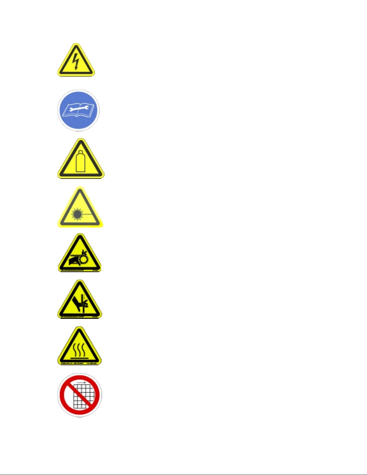
Warnings, Cautions, and Notes
Certain warning symbols are affixed to the machine and correspond to notations in this manual. Before
operating the workcell, identify these warning labels and read the notices described below. Not all labels
may be used on any specific system.
Always wear approved safety glasses when operating or working near the
workcell.
6040
In situations where inattention could cause either personal injury or
damage to equipment a warning notice is used.
6014
Do not smoke near the workcell. Always have a fire extinguisher
available for emergency use.
6019
Before operating the system, read and understand the manuals provided
with the unit.
6017
Before performing any repairs or maintenance to the system, turn off
power and lock out the power disconnect switch.
6011
Never place hands or tools in areas designated by this symbol when the
machine is in operation. A dangerous condition may exist.
6008
Warning notices are used to emphasize that hazardous voltages, current,
temperatures, or other conditions that could case personal injury exist in
this equipment or may be associated with its use. Only qualified
personnel should enter areas designated with this symbol.
6010
Before performing any repairs or maintenance to the system, read and
understand the manuals provided with the unit. Service should only be
performed by a qualified individual.
6018
Exercise caution when pressurized vessels are present. Identify and
repair any leaks immediately. Always wear appropriate safety equipment
when working with pressurized vessels or vessels containing chemicals.
6054
Laser light source present. Do not stare directly into the beam. Do not
use in the presence of highly reflective surfaces.
6003
Pinch hazard from moving parts. Avoid contact.
1012
Shear hazard from moving parts. Avoid contact.
1099
Hot surface. Avoid contact.
6043
Do not remove protective guarding.
6060

This document is based on information available at the time of its publication. While efforts have been
made to be accurate, the information contained herein does not purport to cover all details or variations in
hardware or software, nor to provide for every possible contingency in connection with installation,
operation, or maintenance. Features may be described herein which are not present in all hardware and
software systems. Precision Valve & Automation, Inc. assumes no obligation of notice to holders of this
document with respect to changes subsequently made.
Precision Valve & Automation, Inc. makes no representation or warranty, expressed, implied, or statutory
with respect to, and assumes no responsibility for the accuracy, completeness, sufficiency, or usefulness of
the information contained herein. No warranties of merchantability or fitness for purpose shall apply.
This document, including the inform ation contained herein, is the property of Precision Valve &
Automation, Inc. and is considered co nfidential and proprietary information. It is delivered on the
express condition that it not be used, disclosed , or reproduced in whole or in part, for any reason without
prior written consent of Precision Valve & Automation, Inc.
Copyright © 2003 Precision Valve & Automation, Inc.
All Rights Reserved.

Preface
Notice & Disclaimer
This manual applies to one of the following automated workcells produced by Precision Valve &
Automation, Inc.:
o PVA250™
o PVA550™
o PVA750™
o PVA1000™
o PVA2000™
o PVA200C™
o PVA3000™
All machines are refere nced t hroughout the manual as the workce ll. T his manual pr ovide s informat ion and
functionality descriptions covering all the common options and configurations for a workcell. The
particular machine associated with this manual may not contain all items or may have additions. If the
manual refers to an option that was not purchased, ignore that section. If options exist on the machine not
mentioned in this manual, please consult the Optional Equipment section of the Operating Guide for more
information on these additions.
Revisions to This Manual
The following list describes the major revisions in this manual (Rev M (ii) (4/03)) as compared to the
previous versi on:
o Rewrite for latest program revisions (3.01 & 3.02 & 3.03 & 3.04).
o Altered Power Check procedure and added Door Interlock Check procedure.
o Added compatibility for the PVA250™, PVA2000C™, solvent cups, flow monitor, and teach pendant.
2/10/03 TMB
o Updated Power Check procedure. 2/10/03 TMB
o Added PVA750™ references. 8/1/03 TMB
Operation and Maintenance Manual Rev M(ii) 4/03
- iv -

Content of This Manual
Introduction. Provides an overview of the workcell functionality and physical characteristics.
Installation and Setup. Describes the procedures for installing the workcell and preparing the system for
use. Included in this chapter are instructions for unpacking, inspecting, and installing the workcell.
Operating Safety. Basic safety practices are reviewed. The safety devices and guarding for the workcell
are described.
Operation. Describes system operations of the workcell. It includes a discussion of the system power-up
and power-down sequences and modes of operation.
Troubleshooting. Provides a guide to troubleshooting the workcell. A fault diagnosis table is used to lead
the operator through common problems and sol ut i ons. Several troublesho oting procedures are described.
Maintenance. Provides a preventive maintenance schedule and replacement procedures.
Appendix A – Definitions. Definitions for commonly used terms.
Appendix B – Serial Communication. A brief overview of establishing communication with the workcell.
Appendix C – Error Codes. A list of error codes that may be encountered while using the workcell.
Appendix D – Open Loop Velocity Settings. A list of maximum velocity settings for an open loop drive
system.
Appendix E – Wiring Schema tic Legend. A l egend for t he number ing and c olo r c odi ng used i n the co ntro l
enclosure for the workcell.
Operation and Maintenance Manual Rev M(ii) 4/03
- v -

Contents
Table Of Contents
Preface ......................................................................................................................................... iv
Notice & Disclaimer............................................................................................................................. iv
Revisions to This Manual .....................................................................................................................iv
Content of This Manual......................................................................................................................... v
Contents....................................................................................................................................... vi
Table Of Contents................................................................................................................................. vi
List of Tables........................................................................................................................................ix
Introduction................................................................................................................................10
System Description..............................................................................................................................10
Year 2000 Compliance................................................................................................................. 10
Environmental......................................................................................................................................11
Noise Levels................................................................................................................................. 11
Materials/Chemicals..................................................................................................................... 11
Hazards Due to Contact................................................................................................................11
Handling, Transportation and Storage................................................................................................. 11
Handling and Transportation........................................................................................................ 11
Storage..........................................................................................................................................11
Installation and Setup................................................................................................................ 12
Unpacking and Inspection....................................................................................................................12
Installation...........................................................................................................................................12
Operating Environment........................................................................................................................ 13
Location........................................................................................................................................13
Temperature and Humidity........................................................................................................... 13
Dip Switch Settings..............................................................................................................................13
Operator Interface Dip Switch Settings ............................................................................................... 14
Software............................................................................................................................................... 14
Main program file.........................................................................................................................14
PathMaster®.................................................................................................................................14
Project File ................................................................................................................................... 14
Machine Communications ................................................................................................................... 14
SMEMA ....................................................................................................................................... 14
Operating Safety ........................................................................................................................ 16
Notices and Warnings.......................................................................................................................... 16
Safety Devices and Guarding............................................................................................................... 16
Safety Circuit................................................................................................................................ 16
Lexan Guarding............................................................................................................................ 16
Doors............................................................................................................................................16
Light Curtain.................................................................................................................................17
Exhaust Fan.................................................................................................................... .............. 17
Operation .................................................................................................................................... 18
Startup Procedure.................................................................................................................................18
Operation and Maintenance Manual Rev M(ii) 4/03
- vi -

Light Tower Operation........................................................................................................................ 18
Exhaust Verification............................................................................................................................ 18
Machine Safety Check.........................................................................................................................19
Homing the Axes ................................................................................................................................. 19
Standby Position.................................................................................................................................. 20
Solvent Cups ........................................................................................................................................20
Flow Monitor System...........................................................................................................................20
Priming the Flow Monitor ............................................................................................................ 20
Determining the Correct Material Volume...................................................................................21
Setting the Material Volume Check..............................................................................................21
Auto Cycle Flow Error ................................................................................................................. 21
Flow Monitor Calibration.............................................................................................................22
Flow Control Mode.......................................................................................................................22
Calibration Procedures......................................................................................................................... 23
Standard Needle Calibration......................................................................................................... 23
Operator Defined Needle Calibration...........................................................................................23
Sensor Defined Needle Calibration.............................................................................................. 23
Shutdown Procedure............................................................................................................................23
Cycle Stop............................................................................................................................................ 24
Program Selection................................................................................................................................ 24
Needle Calibration............................................................................................................................... 24
Standard........................................................................................................................................25
Operator Defined.......................................................................................................................... 25
Sensor Defined .............................................................................................................................25
Manual Mode....................................................................................................................................... 26
Valve Selection....................................................................................................................................27
Automatic Mode.................................................................................................................................. 27
Status Mode......................................................................................................................................... 28
Status Sequence................................................................................................................................... 28
Setup Mode.......................................................................................................................................... 29
Conveyor Control................................................................................................................................29
Trackball Control................................................................................................................................. 30
Teach Pendant...................................................................................................................................... 31
OIT Jog Control................................................................................................................ ................... 31
Fault Recovery..................................................................................................................................... 33
Recovering from Emergency Stop and Other Machine Errors......................................................33
Pneumatic Error Recovery Procedure........................................................................................... 34
Run-Time Error Recovery Procedure........................................................................................... 35
Position Error Recovery Procedure.............................................................................................. 35
Limit Error Recovery Procedure................................................................................................... 36
Stop Codes.................................................................................................................................... 36
Startup Errors................................................................................................................................36
Subroutine Error........................................................................................................................... 37
Troubleshooting......................................................................................................................... 38
If Something Goes Wrong . . . .............................................................................................................38
Calling Technical Support............................................................................................................38
Fault Diagnostic...................................................................................................................................38
Closed Loop Servo Systems......................................................................................................... 38
Open Loop Stepper Systems...................................................................................................... ... 41
Controller Master Reset.......................................................................................................................44
Request Controller Version..................................................................................................................44
EEPROM Upgrade Procedure............................................................................................................. 44
Power Check........................................................................................................................................ 45
Operation and Maintenance Manual Rev M(ii) 4/03
- vii -

Door Interlock Check...........................................................................................................................46
Encoder Feedback Test........................................................................................................................ 46
Motor Feedback Test........................................................................................................................... 47
Maintenance ............................................................................................................................... 48
Schedule............................................................................................................................................... 48
Procedures ........................................................................................................................................... 50
Ball Screw Slides.......................................................................................................................... 50
Inspection .....................................................................................................................................50
Conveyor Belt Replacement......................................................................................................... 50
Valves...........................................................................................................................................50
Servicing the Inline Material Filter............................................................................................... 50
Exhaust Fan Setup........................................................................................................................ 51
Pressure Differential Switch Setup ...............................................................................................51
Appendix A – Definitions........................................................................................................... 52
Appendix B – Serial Communication....................................................................................... 54
Serial Communication..........................................................................................................................54
Overview ......................................................................................................................................54
9 Pin Serial Connector..................................................................................................................54
25 Pin Serial Connector................................................................................................................54
Computer 9 Pin to workcell Programming Port............................................................................55
Computer 25 Pin to workcell Programming Port..........................................................................55
Appendix C – Error Codes......................................................................................................... 56
DMC Error Codes................................................................................................................................ 56
Appendix D – Open Loop Velocity Settings............................................................................ 58
Maximum Velocity settings................................................................................................................. 58
Appendix E – Wiring Schematic Legend ................................................................................. 59
Wire Numbering.................................................................................................................................. 59
Wire Color Code.................................................................................................................................. 59
Operation and Maintenance Manual Rev M(ii) 4/03
- viii -

List of Tables
Table 1 – DMC-1500 Dip Switch Settings................................................................................................. 13
Table 2 – DMC-2100 Dip Switch Settings................................................................................................. 13
Table 3 – OIT Jumper Settings................................................................................................................... 14
Table 4 – Light Tower & Buzzer Status..................................................................................................... 18
Table 5 – Stop Code Definitions................................................................................................................. 36
Table 6 – PVA550™, PVA1000™, PVA2000™ and PVA3000™ systems Fault Diagnosis.................... 38
Table 7 – PVA250™, PVA750, and PVA2000C Fault Diagnosis............................................................. 41
Table 8 – Preventive Maintenance Schedule.............................................................................................. 48
Table 9 – DTE 9 Pin Serial Connector .......................................................................................................54
Table 10 – DTE 25 Pin Serial Connector ...................................................................................................54
Table 11 – Cable for Computer DB9 to workcell....................................................................................... 55
Table 12 – Cable for Computer DB25 to workcell..................................................................................... 55
Table 13 – DMC Error Codes..................................................................................................................... 56
Table 14 – PVA250™ Velocity Limits........................................................................................................58
Table 15 – PVA750™, PVA2000C™ Velocity Limits.............................................................................. 58
Table 16 – Wire Numbering....................................................................................................................... 59
Table 17 – Wire Color Code....................................................................................................................... 59
Operation and Maintenance Manual Rev M(ii) 4/03
- ix -
Introduction
System Description
The workcell has been designed specifically for applications involving industrial dispensing and conformal
coating. The flexibility of the machine allows it to be used effectively for a wide range of applications.
The valves are mounted to the end effector of a two, three or four axis Cartesian robot. All dispensing /
spraying is performed within the lexan enclosed work area. Limits have been imposed on the axes to
prevent damage to the machine. The dispense / spray path and active heads are controlled by a program
stored in the motion controller. The controller can store and retrieve up to 30 programs.
NOTE: Not all models are equipped with lexan guarding.
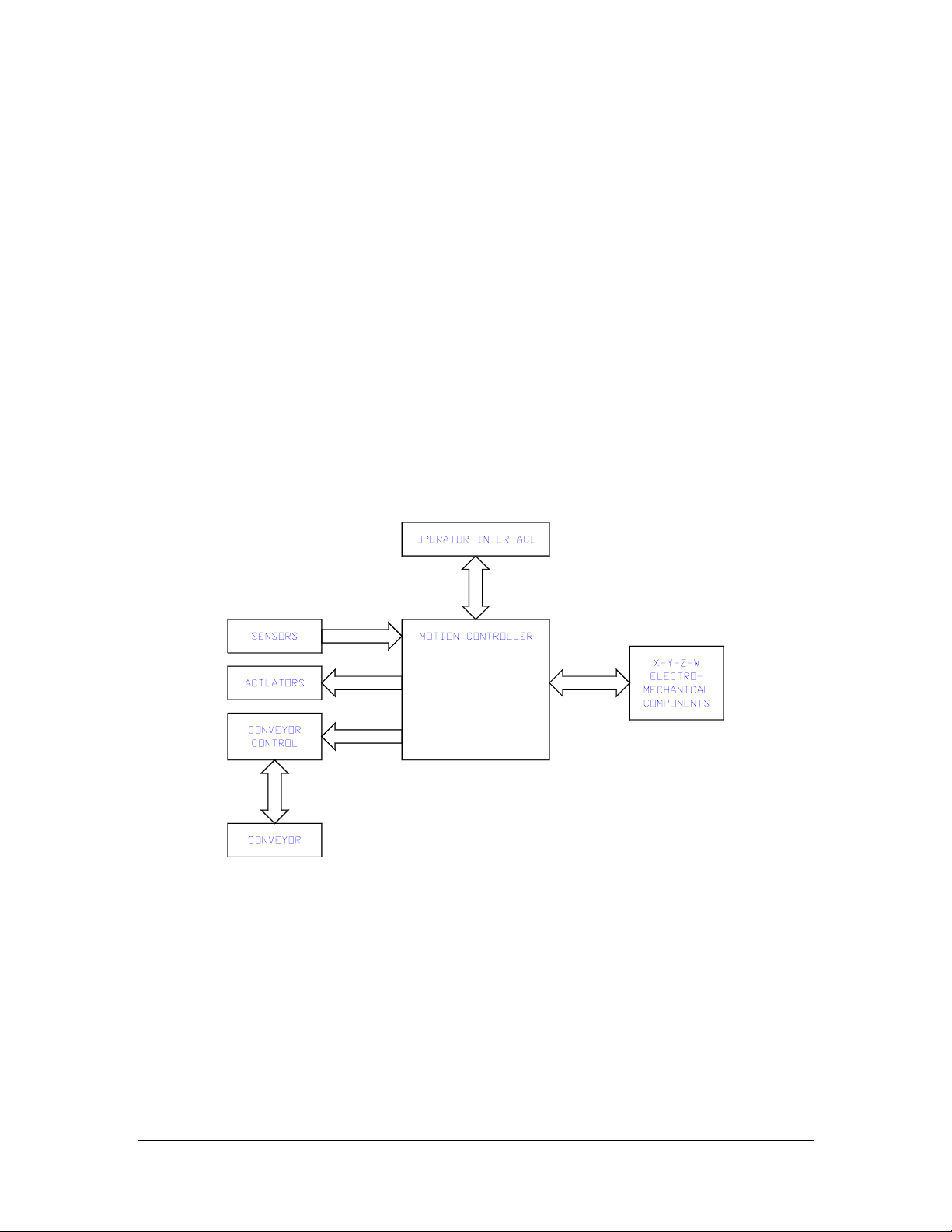
The operator interface permits the operator complete control of the machine. This includes machine setup,
manual operation, program selection and automatic operation. Machine status and error messages are
displayed on the LCD screen and via the optional light tower. It is necessary that operator(s) have read or
by training understand the operation of this machine.
Any uses other than listed above could result in a dangerous condition and cannot be protected against by
the safety features installed on the system.
Figure 1 – workcell Functional Block Diagram
Year 2000 Compliance
The workcell is compliant with and comprehends the year 2000 century date change. The workcell will not
have any operational impediments, malfunction, cease to perform, generate incorrect or ambiguous data
and/or produce incorrect or ambiguous results with respect to same-century and multi-century formulas,
functions, date values and date-data interfaces.
Operation and Maintenance Manual Rev M(ii) 4/03
- 10 -

Environmental
Noise Levels
The audible noise level of the workcell is below 65 dBA.
Materials/Chemicals
There are no dangerous materials or chemicals used in the operation of the machine except for the required
application material. The application material should include a Material Safety Data Sheet (MSDS) which
specifies known dange rs and toxicity.
Hazards Due to Contact
The workcell is designed in such a way as to minimize injury from contact with any accessible portion of
the machine. However, under certain modes of operation, it is possible to enter the work area while the
motion platform is under power. Only a qualified person should do this. All hot surfaces are indicated with
a warning label.
Handling, Transportation and Storage
Handling and Transportation
Handling and transportation should be done in such a fashion as to minimize the vibration and shock
introduced to the system. An air-ride tr uck is reco mmended for ro adway transpor t. Although the machi ne
is designed and built to perform in an industrial environment, excessive abuse will greatly impact the
performance of the machine.
Storage
Dust and Debris
All enclosures and connector covers should be closed tightly. It is recommended that a cover be place over
the system if dust or other airborne debris is present in the storage area.
Temperature and Humidity
Storage should be done in an area at 40°F - 105°F (4°C – 41°C) and low humidity. Condensation should
not be allowed to collect on the machine.
Dispensing / Spraying Equipment
Whenever the machine is to be stored for extended periods of time, the workcell should be flushed using a
solvent compatible with the application material. This includes the following systems, if applicable:
o Dispensing valves, spray valves and servo valves.
o Material lines and hoses.
o Pressure vessels.
o Pumping systems.
Operation and Maintenance Manual Rev M(ii) 4/03
- 11 -

Installation and Setup
WARNING The following procedures should be performed by qualified persons in
accordance with this manual and applicable safety regulations. A “ qualified person” is defined as “a
person or persons who, by possession of a recognized degree or certificate or professional training, or
who, by extensive knowledge, training, and experience, has successfully demonstrated the ability to
solve problems relating to the subject matter and work.” (ref. ANSI/ASME B30.2-1983.)
Unpacking and Inspection
1) Remove all packing materials and strapping. Thoroughly inspect the exterior of the machine for
damage, loose fasteners, etc. Gently move the X & Y axis slides to the center of the work area.
2) At the rear of the machine, inspect all tubing connections, gauges, and regulators.
3) Open the electrical enclosure and visually inspect connectors and components for vibration during
shipping. Close the door, as the machine should not operate with the doors open (All accept .
4) Reinstall the Light tower.
5) Reinstall flow monitor. The flow monitor is typically mounted on the rear of the workcell.
6) Reinstall the main air regulator assembly.
NOTE: Step 3 does not apply to PVA250™ models.
Installation
1) Plug the machine into an appropriate power source as determined by the Machine Specific Information
section of the Operating Guide or the legend plate on the rear of the machine. The electrical service
should be properly grounded, and the power source “clean”. If there is high power equipment
operating off the same source, a line conditioner may be necessary. Errors in machine operation could
indicate poor quality power.
WARNING Failure to comply with electrical specifications can result in damage to the
machine as well as injury to installa tion personnel. Electrical hookup must be made by a qualified
electrician and must comply with any applicable local standards.
2) A ¼” NPT female fitting is provided at the rear of the machine (PVA250™ models have a ¼” quick
disconnect fitting). Connect to a source of clean, dry air. A hose of ¼” inside diameter is sufficient.
3) Ground any pressure vessel to earth or the machine. NOTE: Precision Valve & Automation
STRONGLY recommends the machine not be powered on or material added to the pressure vessels
until they are properly grounded.
4) Close any access doors and push in the EMERGENCY STOP button. At the rear of the machine, turn
on the red air lockout valve (PVA250™ models are not equipped with an air lockout).
5) T urn on power at the red handled switch on the front or rear of the machine (PVA250™ models have a
black “rocker” switch on the rear next to the power cord).
Operation and Maintenance Manual Rev M(ii) 4/03
- 12 -

Operating Environment
Location
The machine should be installed on a level surface away from standing water, possible overspray and
overhead leaks.
Temperature and Humidity
The machine should be operated in an area at 40°F - 105°F (4°C – 41°C) and low humidity. Condensation
should not be allowed to collect on the machine.
Dip Switch Settings
NOTE: During normal operatio n there is no need to adjust the dip switch setting s. If communicatio ns
between the computer and the controller are not reliable, lower the baud rate on both until
communications are satisfactory.
The main RS-232 port on the motion controller must be configured as follows to communicate with the host
computer:
Table 1 – DMC-1500 Dip Switch Settings
Switch Position Description
MRST OFF Master Reset
1200 OFF Baud rate selection
9600 OFF Baud rate selection
19.2K ON Baud rate selection
HSHK ON Hardware Handshaking
(PVA550™, PVA1000™, PVA2000™, and PVA3000™ models)
Table 2 – DMC-2100 Dip Switch Settings
Switch Position Description
MRST OFF Master Reset
XON OFF Software Handshaking
HSHK ON Hardware Handshaking
9600 OFF Baud rate selection
19.2K ON Baud rate selection
38.4K OFF Baud rate selection
OPT OFF Hardware Option
ENET OFF Use Ethernet port as default for
Unsolicited messages.
(PVA250™, PVA750™, PVA2000C models)
CAUTION If hardware handshaking is enabled, the program uses the message command
and a computer is not attached to the Main RS-232 port, the controller eventually halts.
program included with this machine does not contain any message statements.
The
Operation and Maintenance Manual Rev M(ii) 4/03
- 13 -

Operator Interface Dip Switch Settings
NOTE: During normal operation there is no need to adjust the dip switch settings.
The operator interface must be configured to communicate with the controller. The correct settings are
given in the table below. These setting enables 9600 baud, 7 data bits, 1 stop bit and 1 start bit.
Table 3 – OIT Jumper Settings
Jumper Setting
E1 A
E2 A
E3 B
E4 B
E5 A
E6 B
Software
The complete workcell software package consists of several items. To avoid problems and
miscommunication, it is imperative every operator understand what each piece of software is and its
purpose. For more information about PathMaster® and its features, please consult the separate
PathMaster® Manual in the Operating Guide.
Main program file
A text file containing the code that runs the workcell. Under normal circumstances it is not necessary to
change this file, but if needed it can be opened and edited with any text editor, such as Microsoft® Notepad
or Word. The Main program file is downloaded via a drop-down menu in PathMaster® but it should
NEVER be opened within the PathMaster® software.
PathMaster®
Precision Valve & Automation’s Windows®-based programming software. It is used to create, maintain
and download project files for the workcell. The Operating Guide has a separate section on using
PathMaster® to program the workcell.
Project File
A text file containing the code for one or more programs. In almost all cases this file is created within
PathMaster®. This file is downloaded using PathMaster®.
Machine Communications
For manufacturing lines (multiple machines utilizing conveyor systems) it is necessary for the individual
modules to communicate reliably. Therefore, the SMEMA cables must be connected in the correct manner.
NOTE: On the diagrams the J# refers to the label on the machine, not the label on the cable.
SMEMA
The Surface Mount Equipment Manufacturers Association (SMEMA) Electrical Equipment Interface
Standard is used to insure proper sequencing of boards. If these connections are not in place, boards can
not move from one machine to another.
Operation and Maintenance Manual Rev M(ii) 4/03
- 14 -
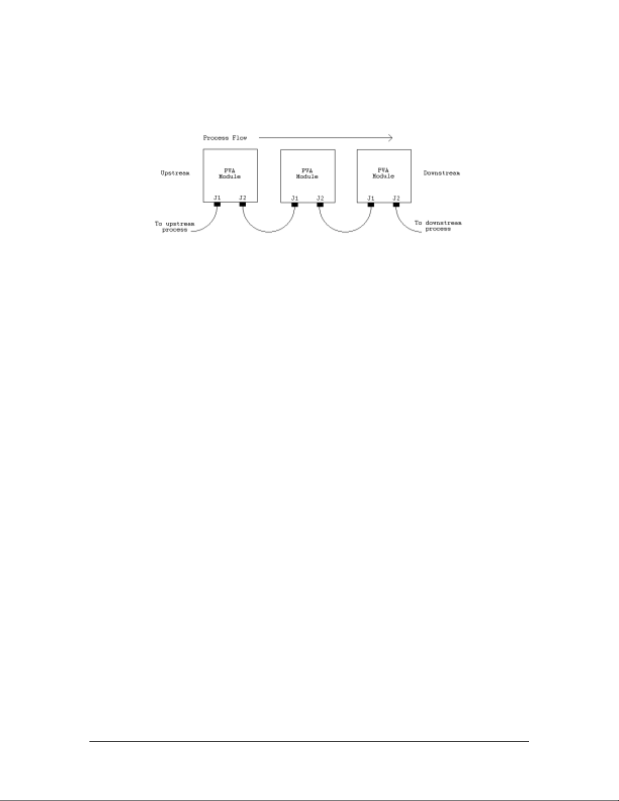
SMEMA cables have male 14-pin amp-type CPC connectors. The cables are straight-through, so
orientation does not matter. On each module, the wire to the J1 (Previous) plug must connect to the J2
(Next) plug on the machine upstream. Similarly, the J2 plug on each machine must connect to the J1 plug
on the machine downstream, as shown in the following diagram:
Operation and Maintenance Manual Rev M(ii) 4/03
- 15 -

Operating Safety
Notices and Warnings
o Safety glasses, gloves, and long sleeved clothing are necessary precautions when working with
automated industrial equipment.
o Read and understand all operating manua l s before using this equipment.
o Do not disable the safety features of the machine.
o Lock-out and tag the air and power supplies before servicing or cleaning any part of this equipment.
o Do not remove any hose, either air or fluid, without relieving the pressure.
o Do not replace any hose with a hose of inadequate pressure rating.
o Use only replacement parts recommended or supplied by the manufacturer.
o Always remain clear of all moving parts when the system is in operation.
Safety Devices and Guarding
The workcell has several safety features that protect the operator from hazards during normal operation of
the machine.
NOTE: The safety fe atures should NEVER be byp assed, disable d or tampered with. Precision Valve &
Automation, Inc. is not responsible for any damages incurred, mechanical or human, because of
alteration or destruction of any safety features.
Safety Circuit
The main power to the machine is monitored and controlled by the safety circuit. The safety circuit
contains two relays, under-voltage protection, and one or more safety devices. The relays are wired in a
redundant manner. Redundancy consists of two parallel relay circuits which work together electrically with
the safety devices. The tripping contacts of the relays are connected in series to insure that the safety circuit
will disconnect power even if one of the relays has failed. Self-checking consists of positive guided
contacts which are mechanically forced to operate together. If one of the redundant relays fails, the power
contacts are opened. The safety devices monitor the state of the EMERGENCY STOP push button and other
safety mechanisms. When the safety relay detects that the one or more of the safety devices has opened, the
power to the motors and pneumatics is cut.
Lexan Guarding
The work area is enclosed with Lexan guarding. The front of the machine is either open, to allow for
manual part loading and unloading, or guarded by doors.
Doors
For machines with an automatic load/unload cycle the front of the machine is protected by two doors. Each
door is monitored by a non-defeatable limit switch. When the door is opened power to the motors and
pneumatics is disconnected. The DOOR BYPASS key switch is provided to allow maintenance personnel
access to the work area without disconnecting power. This bypass switch only allows access during Manual
and Calibration modes.
Operation and Maintenance Manual Rev M(ii) 4/03
- 16 -

Light Curtain
Some machines are equipped with an optional light curtain. The light curtain is redundant and self
checking. The control signals from the light curtain are included as safety devices in the safety circuit. On
machine power up, the light curtain must be reset by turning the key switch to ‘Reset’ for at least ½ second.
Exhaust Fan
Some machines are equipped with an exhaust fan. The exhaust fan is provided to exhaust fumes from the
work area. The exhaust flange should be connected to an appropriate ducting system that is capable of
receiving 150 CFM (cubic feet per minute). Insufficient air flow through the exhaust system generates an
error.
NOTE: Installed safety devices vary from model to model.
Operation and Maintenance Manual Rev M(ii) 4/03
- 17 -

Operation
Startup Procedure
1) Check the fluid and air pressures.
2) Close all doors and turn the DOOR BYPASS key switch to the OFF position (If applicable).
3) Engage the EMERGENCY STOP button.
4) Turn on main power using the red rotary switch at the front or rear of the machine (Black “rocker”
switch on PVA250™ models).
Light Tower Operation
Three stacked indicator lights and a buzzer are used to indicate the status of the machine. The lights are
green, amber, and red with green on the bottom, amber in the middle and red on top. The buzzer is located
below the green light. The lights are visible from all sides of the machine. The indicators operate as
follows.
o The green indicator is on when the machine is in cycle and producing parts. It is off at all other times.
o The amber indicator is on when the machine is in Auto Cycle and ready to produce parts, but can not
cycle due to an external material handling problem (no incoming parts or no room to unload parts).
PVA750™ and PVA2000C™ models are equipped with a light tower but not an amber light.
o The red indicator is on stead y when the machine is not in Auto Cycle due to operator intervention. It
will flash when the machine is in cycle, but cycle is halted due to a machine problem. It is off at all
other times.
o The buzzer cycles with the red indicator during machine errors.
Table 4 – Light Tower & Buzzer Status
State Red Amber Green Buzzer
Cycle Stop ON OFF OFF OFF
Auto Cycle OFF ON OFF OFF
In Cycle OFF OFF ON OFF
Machine Error FLASH OFF OFF FLASH
Exhaust Verification
Once the workcell has initialized, most models will perform an exhaust flow verification process. If
initialization fails, consult the section Startup Errors on page 36. During this process, and whenever the
workcell is in operation the exhaust flow rate is monitored via the on board pressure differential switch.
The workcell must exhaust at a rate no less than 150 cubic feet per minute, otherwise a critical fault will
occur shutting the motors down. The verification process will also attempt to evacuate any potential vapors
that may already exist in the work area of the workcell. The time this process takes will vary from model to
model, but the remaining time for the process will be displayed as in the screen below:
Verifying exhaust. Please wait ...
060
F1 F2 F3 F4 F5 F6 F7 F8
Operation and Maintenance Manual Rev M(ii) 4/03
- 18 -

Machine Safety Check
Once initialize and exhaust verification is complete, the operator interface displays the following message:
Machine Safety Check
Press F1 to initiate.
F1 F2 F3 F4 F5 F6 F7 F8
The machine safety check ensures the workcell safety devices (emergency stop, door interlocks, light
curtain, etc.) are operating properly. During startup, the operator must enter the safety check and complete
it successfully. Otherwise, the machine halts all operations. After pressing F1 the operator is prompted by
the operator interface to activate and deactivate the safety devices and the POWER ON button, if present.
Certain events in this procedure are timed and if an action is not performed within a specified time the
machine interprets this as a failure and displays an error screen such as this:
EStop button failed.
Press F1 to repeat test.
F1 F2 F3 F4 F5 F6 F7 F8
By pressing F1 the operator can repeat the test one time. If a second failure occurs, a screen such as this
appears:
EStop button failed.
Repair and restart the machine.
F1 F2 F3 F4 F5 F6 F7 F8
After the second failure the program ceases functioning and the machine must be restarted. The second
failure need not be for the same device. An emergency stop failure followed by a door interlock failure
halts the program.
If the safety check fails, the entire system should be thoroughly examined by qualified maintenance
personnel before the machine is returned to operation.
Homing the Axes
Press F1 to home the system.
F1 F2 F3 F4 F5 F6 F7 F8
After successfully completing the safety check, the operator is shown the above screen. Pressing F1 homes
the system and displays the following screen:
Operation and Maintenance Manual Rev M(ii) 4/03
- 19 -

Homing axes. Please wait...
F1 F2 F3 F4 F5 F6 F7 F8
The axes home in the following order: Z, W, then X & Y simultaneously.
Standby Position
Once the machine has completed the homing sequence or finishes a required calibration procedure (if so
equipped), it moves to the standby position. Standby is a defined location, DISTINCT from the home
position, although in some circ umstances it may be defined as the same position as home. In most cases,
the standby position is placed near the board stop to minimize travel during Auto Cycle. The workcell
always returns to the standby position in Cycle Stop. If the standby position needs to be changed, please
consult the Main Program Modifications section of the PathMaster® Manual.
Solvent Cups
Some workcells have solvent cups installed as an option. The need for solvent cups is dictated by the
process by which the workcell will be used for. When solvent cusp are installed, the Auto Purge feature is
overridden by the solvent cup routines regardless of the Setup mode settings.
The solvent cup location varies from model to model, however, the location will be somewhere in the
workspace of the workcell. Solvent cups are used as a means of maintaining clean dispense / spray heads.
In Cycle Stop the heads are situated in the solvent cups. In Manual mode, the heads are removed from the
cups and remain out until exiting this mode. In Auto Cycle the heads lift and run the auto purge routine.
They return to the solvent cups after a pre-programmed period of inactivity.
To change the time delay before the heads enter the solvent cups in Auto Cycle, change the variable
SLP_TM in the Machine-Specific Information section of the Main program. A value of 1000 equals 1000
milliseconds or 1 second.
Flow Monitor System
Some workcells have a flow monitor installed as an option. The flow monitor on the workcell measures the
amount of material moving thr o ugh the mater ia l sup p ly line before it is split to supply the individual valves.
It is used as a verification of the dispensing process, not a control of that process, and reports excessive
deviations from desired values. Both the desired material volume and allowable deviation are determined
by the operator.
Priming the Flow Monitor
The flow monitor must be primed prior to use to prevent damage to the unit. Priming the flow
monitor minimizes the amount of air that will pass through the unit during initial startup. Follow the
procedure below to prime the flow monitor.
o Fill the pressure vessel with material and seal.
o Set the material pressure regulator to 0 P.S.I.
o Turn the inlet air and outlet material valve to the closed position.
o Disconnect the material line from the inlet port of the flow monitor.
o Turn the air inlet and material outlet valves to the open position.
Operation and Maintenance Manual Rev M(ii) 4/03
- 20 -

o Slowly increase the material pressure regulator until material flows from the disconnected material line.
o Turn the outlet material valve to the closed position.
o Bleed pressure for pressure vessel and adjust the material pressure regulator to 0 P.S.I
o Reconnect the material line to the inlet port of the flow monitor.
o Open the valve (dispense or spray) using the manual purge procedure outlined in the operations and
maintenance manual.
o Turn the material outlet valve to the open position.
o Slowly increase the material pressure to the target operating pressure.
o Continue the manual purge procedure for each valve until the material flows free of air.
Determining the Correct Material Volume
Before attempting to determine the appropriate material volume, the operator should have a completed path
program, since any changes to a program alters the flow data results. With the completed program loaded
into memory, the operator should enter the Manual mode, position the board correctly with respect to the
board stop s and run a singul ar cycle . For more info rmatio n on the Manual mode, p lea se co nsult pa ge 21 of
the Operation and Maintenance Manual.
After the singular cycle finishes, it displays the follo wing scr een:
Flow Data Set Pt.=00.00cc Dv.=00.0%
Mat.=00.00cc. Press F1 to continue.
F1 F2 F3 F4 F5 F6 F7 F8
The ‘Mat’ value is the amount of material dispensed. The operator should go to the Flow Control mode and
change the flow set point to the ‘Mat’ value that appeared on the flow data screen, then return to the
singular cycle op t ion to run more cycles and verify the consistency of the path program.
NOTE: The above screen does not display if the material target level is set to zero in the Flow Control
mode. See the section Flow Control Mode for information on changing the material target level.
Setting the Material Volume Check
There are two methods of setting the material volume check parameters.
1) Go to the Flow Control mode and adjust the material volume and deviation parameters.
2) Program the settings into the path program. Two variables are used: AC_SET and AC_DEV.
AC_SET is the setpoint for the material flow, which can range from 0 to 99. AC_DEV is the percent
deviation allowed, which can be anywhere from 0 to 99. As an example, entering the following line
into a path program: AC_SET=0.500;AC_DEV=5 would put the volume setting at 0.5 cc and the
allowable deviation at 5%.
If the settings are programmed into the path program, they are used instead of the settings from Flow
Control mode. If no settings are programmed in the path, the machine defaults to the Flow Control mode
settings.
Auto Cycle Flow Error
The Auto Cycle checks the material flow after every cycle if the error is turned ON in the Flow Control
mode. If the volume was within parameters, no indication is given to the operator. In cases where the
Operation and Maintenance Manual Rev M(ii) 4/03
- 21 -

volume was outside acceptable parameters, the flow error screen appears. This screen is similar to the flow
data screen shown above. The board should be removed before returning the machine to operation.
NOTE: Any changes made to settings in the material delivery system (material pressure, stroke
adjustment, etc.) may affect the data from the flow monitor. If this happens, the operator may need to
determine the correct material volume again.
Flow Monitor Calibration
Periodically, the flow monitor calibration should be checked. Start by connecting a PC to the Dispensing
System, open a terminal screen and enter DEZ=0. This resets the flow monitor encoder to zero. Then
dispense 10 c ubic centimete rs of material t hrough any valve, b y means of a manual purge. When finished,
enter MG _DEZ on the terminal screen. This returns a value representing the number of encoder counts
read by the flow monitor. Calculate the flow monitor calibration value: (Encoder Counts / 10) = FC_CAL.
Change the value of the FC_CAL variable in the Machine-Specific Information section of the Main
program to the result of the calculation.
NOTE: For a more precise calibration, d etermine volume by weight. The specific g ravity or density of
the material must be known to do this.
Flow Control Mode
Flow control mode is typically accessed through the Cycle Stop menu using the F2 function key. If access
to Flow Control mode i s not achieved through Cycle Sto p, or if more than one flow monitor is installed on
the workcell, documentation in the Optional Equipment section of the Operator’s Guide will provide details
on these options.
Flow 00.00cc DEV=00.0% Error
EXIT UP DOWN UP DOWN *ON OFF
F1 F2 F3 F4 F5 F6 F7 F8
Flow mode allows control over the flow monitor data that is used as a process check only during Auto
Cycle. These settings are used to determine the material volume and whether or not it is excessive unless
superceded by commands in a path program. The error selection turns the process verification check on and
off. The error ON/OFF selection cannot be overridden by commands in a path program.
[F1] EXIT
[F3] cc UP
[F4] cc DOWN
[F5] DEV UP – Increase the allowable deviation. Maximum is 99%.
[F6] DEV DOWN – Decrease the allowable deviation. Minimum is 0%.
[F7] Error ON – Turn the material flow error checking on. (default)
[F8] Error OFF
– Leave Flow mode and return to Cycle Stop.
– Increase the material target level. Maximum is 99 cc.
– Decrease the material target level. Minimum is 0.00 cc.
– Turn the material flow error checking off.
Operation and Maintenance Manual Rev M(ii) 4/03
- 22 -

Calibration Procedures
The workcell has one of three calibration methods: Standard, Operator Defined and Sensor Defined. If a
Sensor Defined or Operator Defined method is installed on the workcell, the machine may or may not
automatically enter its particular calibration mode following the homing sequence depending on the
application the workcell was set up for. See page 24 for particulars on operating the workcell during a
calibration sequence.
Standard Needle Calibration
The simplest calibration procedure requires the operator to visually inspect the position of a needle with
respect to a calibration point (such as cross-hairs). If the needle is not directly above the point, the operator
must physically reposition the needle so it is above the calibration point.
Operator Defined Needle Calibration
This method is dependent upon the operator utilizing the trackball to redefine the coordinate system
according to the positioning of a specific needle or dispense head. This process is optional. If the specific
needle is located in the desired position this process can be skipped.
The calibration routine automatically runs when the machine is powered on or if the controller is reset. The
head moves to a calibration point (specified in the main program). When at the calibration position the
operator has control of the axes. Using the trackball, the position of the needle tip can be redefined in
reference to a calibration poi nt (such as cross-hairs). T his process can also b e run manually through the
CAL function key if a needle needs to be replaced for any reason during operation.
Sensor Defined Needle Calibration
This method focuses around the NCU (Needle Calibration Unit). The calibration sequence redefines the
coordinate system according to the positioning of a specific needle or dispense head. Limitations may arise
with a multiple head workcell utilizing two or more dispense heads in the same path program.
The NCU is referenced from the home position on the gantry. The start positions for each head to enter the
NCU are referenced from the cross-hair mark on the top of the NCU. The coordinates are defined for each
head using reflective sensors in the NCU. Z is always calibrated first in a downward motion into the Z
sensor. The X and Y coordinates are then calibrated from this position in reference to the positioning of the
NCU in the work area. The needle moves into the next sensor (X or Y) finding the first coordinate, then
moves to the opposite side of the sensor and finds a second coordinate. The calibration routine then
calculates the average of the first and second coordinates and redefines the new position accordingly. This
sequence is repeated for the remaining axis.
Shutdown Procedure
If the machine is in cycle, wait for the cycle to finish and then return to the Cycle Stop mode. If the
machine is in any other mode, the operator should return to Cycle Stop.
1) Press the EMERGENCY STOP button.
2) T urn off power to the system. Rotate the main disconnect switch to the “0” position (Rocker switch on
PVA250™ models).
3) Clean any excess material from the tips of the needles.
4) Remove spray cap(s), wipe tip of needle/seat as well, clean cap thoroughly.
5) If the system will be down for an extended period of time, it is recommended to turn off the air to the
machine. The red lockout valve at the rear of the machine can be used for this (not applicable on
PVA250™ model).
Operation and Maintenance Manual Rev M(ii) 4/03
- 23 -

CAUTION If maintenance is to be performed during the shutdown, be sure to lockout and
tag the machine.
Cycle Stop
Cycle Stop
PROG CAL MAN AUTO STAT SETUP
F1 F2 F3 F4 F5 F6 F7 F8
The Cycle Stop state is the default state for the workcell. All other modes and capabilities can be accessed
from this state through the function key buttons listed below.
[F1] PROG
[F3] CAL – Enter Needle Calibration mode (see page 24).
[F4] MAN – Manually operate the machine (see page 26). Also known as Jog or Teach mode.
[F5] AUTO – Run the machine in Auto Cycle (see page 27).
[F6] STAT – Check the status of certain machine items.
[F8] SETUP – View or change the setup functions of the machine (see page 29).
– Change the active program in Program Selection (see page 24).
Program Selection
Select Program: Program 1
EXIT PREV NEXT
F1 F2 F3 F4 F5 F6 F7 F8
The workcell is capable of storing up to 30 different programs. The program selection menu allows the
operator to choose which program is used during the Auto Cycle mode.
[F1] EXIT
[F2] PREV – Decrement to the previous program.
[F3] NEXT – Increment to the next program.
– Leave program selection and return to Cycle Stop.
Needle Calibration
The end effector may contain dispense (as opposed to spray) heads, each of which has a needle. Whenever
a needle is replaced or the machine is started the needles should be calibrated. When the machine enters
this mode it automatically moves to a pre-set calibration point.
Operation and Maintenance Manual Rev M(ii) 4/03
- 24 -

Standard
Calibration
EXIT HOME
F1 F2 F3 F4 F5 F6 F7 F8
Once at the preset point, the operator must physically reposition the dispense needle to ensure proper
calibration.
[F1] EXIT
[F3] HOME – Home the system.
– Leave needle calibration and return to Cycle Stop.
Operator Defined
Calibration AXIS: X&Y
EXIT RECAL HOME X&Y XYZW
F1 F2 F3 F4 F5 F6 F7 F8
The needle(s) must be positioned over a cross-hair. Once the operator is satisfied that the needle is properly
positioned, selecting RECAL calibrates the system. The operator can use the trackball to move the end
effector.
[F1] EXIT
[F2] RECAL – Execute re-calibration.
[F3] HOME – Home the system. The workcell returns to the pre-set point.
– Leave needle calibration and return to Cycle Stop.
[F4] X&Y – Operate the X and Y axes simultaneously.
[F5] X – Operate only the X axis.
[F6] Y – Operate only the Y axis.
– Operate only the Z axis.
[F7] Z
[F8] W – Operate only the W axis.
Sensor Defined
Calibration
EXIT CAL HOME
F1 F2 F3 F4 F5 F6 F7 F8
The sensor defined calibration is entirely machine run. No operator intervention is required to execute the
sequence.
[F1] EXIT – Leave needle calibration and return to Cycle Stop.
[F2] CAL
– Run the calibration routine. This is automatic and no operator intervention is required.
Operation and Maintenance Manual Rev M(ii) 4/03
- 25 -

[F3] HOME – Home the system. This automatically runs the calibration routine afterward.
Manual Mode
PVA550™, PVA1000™, PVA2000™,
PVA3000™ models.
Jog Mode Head: FC100 Axis: X&Y
EXIT TEACH VLV RUN PURG TP CONV AXIS
F1 F2 F3 F4 F5 F6 F7 F8
PVA250™, PVA000C™ models
Manual Mode Head: FC100
EXIT TEACH VLV RUN PURG RP JOG
F1 F2 F3 F4 F5 F6 F7 F8
Manual mode allows manual control of all devices on the workcell. There are sublevels within Manual
mode used to access different workcell functions. The workcell is considered to be in Manual mode even
when in a sublevel of Manual mode. Manual mode also serves as the Teach mode for all workcell models.
Models equipped with a trackball can jog the gantry via the trackball from Manual mode. An axis
combination can be selected from the trackball as well as the Axis sublevel. Models that are not equipped
with a trackball (PVA250™, PVA750™, PVA2000C™) can jog the gantry using the function keys from
the Jog sublevel menu.
Programming the workcell is accomplished in concert with a PC-compatible computer by using Precision
Valve & Automation’s PathMaster® software. The operator must be in Manual mode, or a sub level of
Manual mode, for PathMaster® to function properly. For more information on programming, please
consult the separate PathMaster® Manual in the Operating Guide.
[F1] EXIT
– Leave Manual mode and return to Cycle Stop.
[F2] TEACH – Program the current point.
[F3] VLV – Switch to Valve Selection (see page 27).
[F4] RUN – Run singular cycles of the current program. Pressing F1 exits the mode and returns the
operator to Manual mode. In this mode the following screen appears, allowing the operator to run 1 cycle
either wet or dry:
Press F2 or F3 to run 1 cycle.
Exit WET DRY
[F5] PURG
F1 F2 F3 F4 F5 F6 F7 F8
– Actuate the current valve.
[F6] TP – Momentary switch that displays the current position of the head in the following manner:
RP – (PVA250™, PVA200C™ models only) Momentary switch that displays the current reference
position of the head in the following manner:
Current Position:
X 000000, Y 000000, Z 000000, W 000000
[F7] CONV
[F8] AXIS
JOG
– (PVA250™, PVA750™, PVA2000C™ models only) Switch to Jog Mode (see page 31).
F1 F2 F3 F4 F5 F6 F7 F8
– Switch to Conveyor Control (see page 29).
– Switch to Trackball Control (see page 30).
Operation and Maintenance Manual Rev M(ii) 4/03
- 26 -

Valve Selection
Valve Functions Head: FC100
EXIT PURG SEL UP DOWN ROTA ROTB
F1 F2 F3 F4 F5 F6 F7 F8
Units equipped with multiple valves have this mode. The active head or valve can be selected from the
Valve sublevel menu. The pneumatics Z-slide(s) and rotary(s) (if equipped) can be actuated from the Valve
submenu.
NOTE: When program ming or operating the workc ell, the valves should NEVER be used for moving
components or boards. Precision Valve & Automation is not responsible for damages incurred from
using the valves in an inappropriate manner.
[F1] EXIT
[F2] PURG – Actuate the current valve.
[F3] SEL – Change the active head.
[F4] UP – Raise the active head’s Z-slide.
[F5] DOWN – Lower the active head’s Z-slide.
[F6] ROTA – Put the rotary in the home position. (default)
[F7] ROTB – Put the rotary in the auxiliary position.
– Leave Valve submenu and return to the previous menu.
Automatic Mode
Auto Cycle WET Count:000000
STOP PROGRAM 1
F1 F2 F3 F4 F5 F6 F7 F8
This mode handles the automatic cycling of the machine. There are three machine setups that may be
encountered:
o Conveyor equipped.
o Stand-alone without a light curtain.
o Stand-alone with a light curtain.
For a workcell with a conveyor, the part is placed for process on the conveyor either by an operator or
mechanically via an upstream process. SMEMA signals are provided with the machine to be used in
conjunction with an upstream process. The part is recognized at the entrance to the machine and is shuttled
to the stop for cycling. Once against the stop the part is registered and dispensed / sprayed on. Once the
program finishes, the board is released and shuttled to the downstream end of the conveyor to await any
process that may follow. Once released or removed, the process is set to repeat itself.
For machines without a conveyor, all parts must be placed in the workcell manually. Part-in-place sensors
detect if a board is present or not. If a board is misplaced in the cell, the operator is alerted of the fact.
Once a machine is ready for cycling, the operator must activate the hand switches to process parts. All parts
must be removed after cycling before a new cycle may begin.
Operation and Maintenance Manual Rev M(ii) 4/03
- 27 -

If the workcell possesses a light curtain, it operates in a similar manner as a stand-alone model without a
light curtain. However, the light curtain may be used to initiate cycles (bypassing the hand switches).
Screen during cycle. Screen with valves deactivated.
In Cycle... Count:000000
STOP PROGRAM 1
F1 F2 F3 F4 F5 F6 F7 F8
Auto Cycle DRY Count:000000
STOP PROGRAM 1
F1 F2 F3 F4 F5 F6 F7 F8
Status Mode
Status SMEMA Up Ready DN BA
EXIT STAT INP ON *OFF ON *OFF
F1 F2 F3 F4 F5 F6 F7 F8
The status mode a llows the oper ator to check a number o f machine paramete rs, running an entire seque nce
when STAT is selected from within this mode. When the workcell is placed in-line, SMEMA signals
ensure communication with the upstream and downstream machines. The operator can check the inputs to
the workcell and change the Up Ready and Down Board Available output signals.
[F1] EXIT
[F3] STAT – Switch to the Status Sequence (see page 28).
[F4] SMEMA INP – Check the status of the SMEMA inputs (momentary). Displays the following screen:
– Leave Status mode and return to Cycle Stop.
Up Board Available: OFF
Down Ready: OFF
[F5] Up Ready ON
F1 F2 F3 F4 F5 F6 F7 F8
– Turn the Up Ready signal on.
[F6] Up Ready OFF – Turn the Up Ready signal off. (default)
[F7] DN BA ON – Turn the Down Board Available signal on.
[F8] DN BA OFF
– Turn the Down Board Available signal off. (default)
Status Sequence
The status features are available via the setup mode and whenever the machine encounters a position error,
limit error or command error. It gives information on the status of the axes that may be helpful in
debugging a proble m. Once the operato r enters the status mode, exiting is allowed at any time by pressing
F8, while pressing F1 scrolls the operator through the screens.
Machine Status Report. Press F1 to
scroll through screens, F8 to quit.
F1 F2 F3 F4 F5 F6 F7 F8
Operation and Maintenance Manual Rev M(ii) 4/03
- 28 -

Encoder Status (all except PVA250™) Motor Status
X-axis Enc.Pos. Com.Pos. Pos.Err.
F1 F2 F3 F4 F5 F6 F7 F8
000000 000000 000000
X-axis Motors On/Off Torque Tor.Lim.
F1 F2 F3 F4 F5 F6 F7 F8
ON 0.0000 0.0000
Sensor Status Tuning Status
X-axis Sensors Home For.Lim. Rev.Lim.
F1 F2 F3 F4 F5 F6 F7 F8
OFF OFF OFF
X-axis Tuning KD KP KI
F1 F2 F3 F4 F5 F6 F7 F8
000.00 000.00 000.00
Setup Mode
Setup Counter Auto Purge Run Mode
EXIT CNT RES ON *OFF WET *DRY
F1 F2 F3 F4 F5 F6 F7 F8
Setup mode allows the operator to control basic functions of the machine. The valves can be turned off
during Auto Cycle by setting the run mode to dry. This option does NOT affect the run option in the
Manual mode, which is user selected as a wet or dry run.
The auto purge feature dispenses / sprays material from all valves at specific intervals to prevent valves
from clogging. The auto purge default setting is dependent upon the type of material used in the workcell.
The workcell only auto purges when in Auto Cycle or Cycle Stop. If the workcell is in any other state, it
does not auto purge. However, it immediately auto purges, if necessary, once returning to Cycle Stop or
Auto Cycle.
NOTE: If the workcell is equipped with solvent cups the auto purge feature is overridden by the solvent
cup routines. The system will purge only when needed acco rding to the solvent cup sequence, regardless
of the auto purge setting in Setup mode.
[F1] EXIT
– Leave Setup mode and return to Cycle Stop.
[F2] Counter CNT – Display the current cycle count.
[F3] Counter RES
– Reset the cycle count to zero.
[F5] Auto Purge ON – Enable the auto purge feature.
[F6] Auto Purge OFF – Disable the auto purge feature.
[F7] Run Mode WET
– Dispense / spray material during Auto Cycle. (default)
[F8] Run Mode DRY – Material does not dispense / spray during Auto Cycle.
Conveyor Control
Conveyor Control Conveyor Stop
EXIT ON OFF ON OFF
F1 F2 F3 F4 F5 F6 F7 F8
The conveyor and stop are controlled in this mode so the operator can position boards in the workcell.
Operation and Maintenance Manual Rev M(ii) 4/03
- 29 -

[F1] EXIT – Leave Conveyor Control and return to the previous mode.
[F5] Conveyor ON – Turn the conveyor on.
[F6] Conveyor OFF
[F7] Stop ON
[F8] Stop OFF – Turn the board stop off.
– Turn the conveyor off.
– Turn the board stop on.
Trackball Control
(All models except PVA250™, PVA750™, PVA2000C™)
Trackball Control Current: X&Y
EXIT TEACH PURG X&Y XYZW
F1 F2 F3 F4 F5 F6 F7 F8
Trackball Control allows the operator to switch the active axis on the trackball.
[F1] EXIT
[F2] TEACH – Program the current point.
[F3] PURG – Actuate the current valve.
[F4] X&Y – Operate the X and Y axes simultaneously.
[F5] X – Operate only the X axis.
– Leave Trackball Control and return to the previous mode.
[F6] Y – Operate only the Y axis.
[F7] Z – Operate only the Z axis.
[F8] W – Operate only the W axis.
Operation and Maintenance Manual Rev M(ii) 4/03
- 30 -

Teach Pendant
PVA550™, PVA2000™, and PVA3000™ are equipped with a teach pendant which has a trackball, teach
button, purge button, axis selection button, and LED indicators for selected axes and teach function.
TRACKBALL
Teach – The teach button mimics the teach button found on the workcell OIT in that it will register the
gantry position back to PathMaster® when teaching a motion profile.
Purge
– The purge button mimics the purge button found on the workcell OIT in that it will purge material
from the active valve.
Axis
– The axis butt on allows the operator to toggle through the ava ilable axis configurati ons. Typical
configurations are X only, Y only, Z only, W only, and X & Y together.
LED’s
– The X, Y, Z and W LED’s represent the selected axis configuration. The teach LED indicates a
successful response from PathMaster® when a position is taught. The teach LED is accompanied by a
‘beep’ from the light tower buzzer.
– The trackball allows the operator to jog each axis independently or X and Y together.
OIT Jog Control
(PVA250™, PVA750™, PVA2000C™ models only)
Jog Mode Current: X&Y
EXIT TEACH PURG AX IS - Y -X +X +Y
F1 F2 F3 F4 F5 F6 F7 F8
OIT Jog Control allows the operator to jog the gantry via the OIT function keys to perform teach functions.
[F1] EXIT
[F2] TEACH – Program the current point.
[F3] PURG – Actuate the current valve.
[F4] AXIS – Toggle axis control between X, Y and Z.
– Leave OIT Jog Control and return to the previous mode.
Operation and Maintenance Manual Rev M(ii) 4/03
- 31 -

[F5] -Y – Jog the Y axis in the negative direction.
[F6] -X – Jog the X axis in the negative direction.
[F7] +X
[F8] +Y
– Jog the X axis in the positive direction.
– Jog the Y axis in the positive direction.
To jog an axis, press and hold the function key that corresponds to the axis and direction of motion desired.
Once the axis is in motion for approx. 1 sec, the speed will increase by a factor of 15.
Operation and Maintenance Manual Rev M(ii) 4/03
- 32 -

Fault Recovery
Recovering from Emergency Stop and Other Machine Errors
If the operator uses one of the EMERGENCY STOP push buttons or the machine encounters a system error,
this procedure should be followed to return the machine to the Cycle Stop state.
NOTE: The PVA250™, PVA750™, and PVA2000C models will require the workcell to rehome after
recovering from and EMERGENCY STOP, or any other error.
WARNING If the EMERGENCY STOP was activated because of system failure, DO NOT
release the EMERGENCY STOP. Shutdown the system and have qualified personnel repair the
machine.
Emergency Stop. Reset button
to continue the program.
F1 F2 F3 F4 F5 F6 F7 F8
1) After reset, press F1 to return the head to the standby position. The screen returns to Cycle Stop.
Press F1 to return head to standby.
OK
F1 F2 F3 F4 F5 F6 F7 F8
2) Correct the fault which prompted the operator to emergency stop the machine (open the door, etc).
3) Open the access door.
4) Remove all parts from the work area. Determine which parts can be re-worked and put them in the
input queue.
5) Close the access door.
6) Follow the Startup Procedure.
Recovery from a door error, resulting from a door being open while the DOOR BYPASS switch is in the
OFF position, is handled in a similar manner as an emergency stop. Depending upon the machine setup,
other errors could occur, such as low air pressure, low material flow or insufficient exhaust air flow. As
with an emergency stop, these errors should be corrected first, then the operator should follow the startup
procedure to continue.
Examples of the other possible error screens:
Door Error Low Air Pressure
Left Door open. Close
to continue the program.
F1 F2 F3 F4 F5 F6 F7 F8
Operation and Maintenance Manual Rev M(ii) 4/03
Air Pressure low. Repair
to continue the program.
F1 F2 F3 F4 F5 F6 F7 F8
- 33 -

Low Material Level Low Exhaust Flow
Material A Level low.
Press F1 to continue.
F1 F2 F3 F4 F5 F6 F7 F8
Exhaust Fl ow low.
Repair and press F1.
F1 F2 F3 F4 F5 F6 F7 F8
Low Air Pressure
There is an air pressure gauge mounted on the main regulator at the rear of the machine, which may include
a low pressure sensor. This is designed as a gross check to verify the main air pressure is being fed to the
machine. This prevents damage to moving parts on the end effector. It does not detect slight fluctuations in
line pressure but it does detect brief dips below the set point. If such an instance occurs, the machine goes
to error for five seconds, then clears the error. The operator must either increase the air pressure or
decrease the set point to prevent such an error from happening again.
If any air pressure error is encountered, follow these steps to return the machine to normal operation:
1) Verify that the air pressure is ON.
2) Check that the main air pressure regulator is set for 80-100 P.S.I.
3) If the above settings are correct, and the output light indicator on the air pressure gauge is still lit,
verify the setpoint for the air pressure alarm. Consult the separate are pressure sensor manual for
information on setting the air pressure set point.
4) Adjust the set point for approximately 65-75 P.S.I.
5) Restart the machine. If the error persists, the air pressure sensor may be damaged.
Low Material Level
The workcell onl y checks the material level( s) when running cycles. If there is a materia l level error, the
machine can operate in all its modes (except for cycles) until the material level is reestablished.
Resetting the Exhaust Fan Overload Relay
Machines with exhaust fans may encounter errors when the overload relay trips. Follow these steps to
return the machine to normal operation:
1) Turn machine power OFF.
2) Open the electrical enclosure.
3) Check the tripped flag on the overload relay.
4) Verify that the current setpoint is set properly on the overload relay. Check the rating on the exhaust
fan housing for cur rent draw.
5) If necessary, push the reset button to reset the relay.
6) Restart the machine. If the problem persists, consult the Troubleshooting section on page 38 for more
information.
Pneumatic Error Recovery Procedure
The system pneumatics are checked for errors any time they operate. In addition, any movements to home
or the standby position require the pneumatics to be in their “home” position before proceeding. If a
pneumatic fails, it generates an error such as the one below.
Operation and Maintenance Manual Rev M(ii) 4/03
- 34 -

FC100 Z-slide down failed.
Repair and press F1.
F1 F2 F3 F4 F5 F6 F7 F8
The operator should determine the cause of the problem before pressing F1 and continuing. Refer to the
pneumatic actuator failure section of Troubleshooting (page 38) for more information about diagnosing the
problem.
Run-Time Error Recovery Procedure
A run-time error is generated during the execution of the program. For more information about
programming, please refer to the separate PathMaster® Manual. This type of failure should not be
encountered during normal operation of the machine. The most common cause for this type of failure is
when using PathMaster® ver. 2.1 or higher and attempting to playback an area function without first
downloading a properly formatted project file to the workcell. The operator can check the machine’s status
screens by selecting F5.
Error 000 on line 0000.
Press F1 to restart, F5 for status.
F1 F2 F3 F4 F5 F6 F7 F8
Position Error Recovery Procedure
(All models except PVA250™, PVA750™, PVA2000C™)
A position error is caused when the difference between the commanded position and the current position
exceeds the maximum allowable error for an axis. The error limit is defined to be approximately 1/5”. For
most cases this is 1000 counts. The error limit can be reached if the dispense / spray head reaches a hard
stop, in Manual mode, if the speed or acceleration is set too high or if the axes drives are not powered.
Check the EMERGENCY STOP button. The operator can check the machine’s status screens by selecting
F5.
Position Error. F1-restart, F5-status.
Stop codes (x,y,z,w) 000, 000, 000, 000
F1 F2 F3 F4 F5 F6 F7 F8
1) Open the access door.
2) Move the dispense / spray head to the center of the work area. The Z axis is equipped with a brake.
The motor coupling can be turned by hand to move the head towards the center of the work area.
3) Close the access door.
4) Press F1 to clear the error.
5) Follow the startup procedure.
Operation and Maintenance Manual Rev M(ii) 4/03
- 35 -

Limit Error Recovery Procedure
The machine encounters a limit error in the following cases. First, if the path program attempts to move the
dispense / spray head past one of the software limits. If a software limit caused the error, then either the
path or the software limits must be changed. The operator can check the machine’s status screens by
selecting F5.
Limit Error. F1-restart, F5-status.
Stop codes (x,y,z,w) 000, 000, 000, 000
F1 F2 F3 F4 F5 F6 F7 F8
1) Open the access door.
2) Move the dispense / spray head to the center of the work area. The Z axis is equipped with a brake (all
model except PVA250™). The motor coupling can be turned by hand to move the head towards the
center of the work area.
3) Close the access door.
4) Press F1 to clear the error.
5) Follow the startup procedure.
Stop Codes
(All models except PVA250™, PVA750™, PVA2000C™)
For Position and Limit Errors, the error screen displays the stop codes for all the motors. This information
tells the operator which axis (or axes) caused the machine to go to fault.
Table 5 – Stop Code Definitions
0 Motors are running, independent mode.
1 Motors stopped at commanded independent position.
2 Decelerating or stopped by FWD limit switch or software limit, FL.
3 Decelerating or stopped by REV limit switch or software limit, BL.
4 Decelerating or stopped by Stop Command (ST).
6 Stopped by Abort input.
7 Stopped by Abort command (AB).
8 Decelerating or stopped by Off-on-Erro r (OE1).
9 Stopped after Finding Edge (FE).
10 Stopped after Homing (HM).
50 Contour running.
51 Contour Stop.
99 MC timeout.
100 Motors are running, vector sequence.
101 Motors stopped at commanded vector.
Startup Errors
The pro gram save s seve ral vari able s in the EEP ROM t hrough p ower-do wn. If the var iab les ar e not p rese nt
or they are out of bounds the following message is displayed. The program automatically initializes the
variables and recover from the error.
Operation and Maintenance Manual Rev M(ii) 4/03
- 36 -

Variable error.
Initializing...
F1 F2 F3 F4 F5 F6 F7 F8
If the error occurs more than one time during the startup of the machine, the following message is displayed.
This indicates a bug in the main program. The original program should be downloaded to the controller.
Unrecoverable variable error during
startup. Restart the machine.
F1 F2 F3 F4 F5 F6 F7 F8
Another potential error occurs when the machine “hangs” on initialization, displaying the following screen
(which never changes):
Precision Valve & Automation, Inc.
System Initialization, please wait...
F1 F2 F3 F4 F5 F6 F7 F8
In almost all cases, this occurs when a program’s length exceeds the maximum available space in RAM or a
defective function key. The solution for this problem is to shorten the active program, or replace the
function key membrane panel. Consult the separate PathMaster® Manual in the Operating Guide for more
information on altering a program.
Subroutine Error
A Subroutine error occurs if the path programs have not been loaded correctly into segment 1, 2 or 3 of
memory. During the Startup Sequence and after Program Selection the main program attempts to load the
current program from the segment memory. If the subroutine can not be found the following message is
displayed. Please refer to the PathMaster® Manual for more information about downloading.
Subroutine error. The subroutine is not
stored in segment 1, 2 or 3.
F1 F2 F3 F4 F5 F6 F7 F8
Operation and Maintenance Manual Rev M(ii) 4/03
- 37 -

Troubleshooting
If Something Goes Wrong . . .
Some problems encountered when using the workcell are easy to identify and solve. Others require more
extensive help. This troubleshooting section is designed to assist an op erator in solving problems before
seeking additional help. It is strongly recommended the operator check this section first if a mechanical or
electrical problem occurs. Remember, not every problem can be described in this section, but this should
be a good place to start.
NOTE: If a problem occurs while running a particular path program, consult the separate
PathMaster® Manual for information on debugging code problems.
Calling Technical Support
The technical support staff is always available to help solve any problems. The phone number is (518) 371-
2684. To assist in the troubleshooting process, it is best if as many of the following items are addressed
before calling for help:
1) Record all the information on the OIT when the error occurred.
2) Take note of the operation in progress when the machine developed trouble (when did it have
problems, what was it doing, etc.).
3) If the error was not serious, attempt to repeat the error. If the error does not repeat, the problem may
have been op erator generated .
4) Use a terminal screen to communicate with the controller. Most troubleshooting necessitates issuing
commands directly to the controller.
5) If the problem is programming related, a hard copy or email of the program in question may be
requested by PVA. Please be prepared to send it. The PVA fax number is (518) 371-2688, or the
customer service representative will provide an email address, if all parties are email capable.
Fault Diagnostic
The PVA550™, PVA1000™, PVA2000™, and PVA3000™ models use a closed loop servo drive system
were as the PVA250™, PVA750™ and PVA2000C™ models use an open loop stepper drive system.
Listed below are are general fault diagnostic table for each type of system.
Closed Loop Servo Systems
Table 6 – PVA550™, PVA1000™, PVA2000™ and PVA3000™ systems Fault Diagnosis
Operation Other Symptoms Possible Cause Corrective Action
Turn the machine
ON. The operator
interface does not
have power.
The electrical
Cables are loose or not
connected.
The electrical enclosure is
enclosure does not
have power.
open, so the electrical
enclosure safety switch is in
the open position.
• Check the cable
connections. Correct any
loose connections.
• Close the electrical
enclosure.
Operation and Maintenance Manual Rev M(ii) 4/03
- 38 -

Operation Other Symptoms Possible Cause Corrective Action
Blown fuse.
• Check FU-1 which is
located inside the electrical
enclosure. Replace if
necessary.
Homing the axes.
The end effector
moves past the
Home sensor is out of
position or too far away
from the homing tab.
home sensor and
hits the hard stop.
Sensor cable is loose or not
connected.
Homing the axes.
The Z axis does not
move.
End effector can be
moved freely when
the power is on.
SSR-1 is not ON
when the Z axis
drive is enabled.
SSR-1 is ON when
the Z axis drive is
The EMERGENCY STOP
push button is depressed.
The Z axis brake is not
disengaging when the drive
is enabled.
The fuse for SSR-1 is blown
or SSR-1 is damaged.
enabled.
Axis does not move. Encoder works
according to the
Encoder Feedback
The axis speed or
acceleration has been set to
zero.
Test on page 46.
• Depress the EMERGENCY
STOP push button. Move
the axis by hand until the
homing tab moves into the
home sensor. The se nsor
should be on. Loosen the
lock nut on the sensor and
readjust to .020” gap.
• Check the cable
connections. Correct any
loose connections.
• Release the EMERGENCY
STOP push button.
• Check the SSR-1 wiring. It
should be on when the Z
axis drive is enabled.
• Check the fuse using an
OHM meter. Replace
component if necessary.
• Set the speed and
acceleration to a positive,
non-zero value usi ng the SP
and AC commands.
Axis drive light is
Axis drive is not enabled.
RED.
The axis cables are loose or
not connected.
The EMERGENCY STOP
push button is depressed.
Hall effect sensors are not
correctly connected.
The axis amplifier is bad.
Operation and Maintenance Manual Rev M(ii) 4/03
- 39 -
• Enable the drive using the
SH command.
• Check the cable
connections. Correct any
loose connections.
• Release the EMERGENCY
STOP push button.
• Check the cable connections
for the axis. Correct any
loose connections.
• Check the hall effect sensor
phasing using the electrical
drawings.
• Replace the amplifier.

Operation Other Symptoms Possible Cause Corrective Action
Axis runs away. Motor power connections
are wired incorrectly.
• Check the phasing using the
electrical drawings.
Z axis encoder
does not work.
Z axis encoder/brake cable
is loose or not connected.
The axis amplifier is bad.
Pneumatic actuator
failure.
Pneumatics work
slowly.
Air lockout valve on the rear
of the machine is in the OFF
position.
Insufficient air pressure.
Restricted air line.
Loose Fitting or Tubing
Connection.
Frayed or damaged air line.
• Check the cable
connections. Correct any
loose connections.
• Replace the amplifier.
• Turn the lockout valve to
the ON position.
• Check and adjust the system
pressures to the correct
values. Please refer to the
Machine Specific
Information section of the
Operating Guide for
particular pressure settings.
• Correct any tight bends or
restrictions in the air lines.
• Tighten connection.
• Replace the damaged air
line(s).
Sensor is not positioned
correctly.
Part in place sensor
failure.
Conveyor does not
Cable is loose or not
connected.
Conveyor belt stuck to rails.
run.
No power to
conveyor motor.
Control relay not energized
or Power On li ght not
illuminated (Certain
Models).
Exhaust fan does
No air flow. The motor overload relay,
not run.
OL-1, is in the tripped state.
Insufficient air flow capacity
in the factory ducting.
• Adjust the sensor location.
• Check the cable
connections. Correct any
loose connections.
• Clean or replace belt.
• Check voltages and
connections.
• Check conveyor power fuse.
• Reset the exhaust fan
overload relay.
• Check FU-5 in the electrical
enclosure.
• Upgrade the duct to allow
for more air flow.
Operation and Maintenance Manual Rev M(ii) 4/03
- 40 -

Operation Other Symptoms Possible Cause Corrective Action
• Reset the exhaust fan
overload relay.
The filter and
ducting are fine.
The motor
temperature is
normal.
The overload relay current
setting has been changed.
• Verify the current setting on
the overload relay. Please
refer to exha ust fan setup.
• Checked the tripped flag on
the overload relay. Push the
reset button to reset the
relay.
Open Loop Stepper Systems
Table 7 – PVA250™, PVA750, and PVA2000C Fault Diagnosis
Operation Other Symptoms Possible Cause Corrective Action
Turn the machine
ON. The operator
interface does not
have power.
The electrical
Cables are loose or not
connected.
The electrical enclosure is
enclosure does not
have power.
open, so the electrical
enclosure safety switch is in
the open position.
• Check the cable
connections. Correct any
loose connections.
• Close the electrical
enclosure.
The secondary disconnect if
off (PVA750™,
PVA2000C™ only).
Blown fuse.
Homing the axes.
The end effector
moves past the
home sensor and
hits the hard stop.
Sensor cable is loose or not
Limit Error during
homing sequence.
Home sensor is out of
position or too far away
from the homing tab.
connected.
Axes is not
moving.
The amp fuse(s) is blown.
• Check the secondary power
• Check FU-2, FU-3, FU-4
• Depress the EMERGENCY
• Check the cable
• Check F1-F5 fuses located
disconnect located on the
left side of the electrical
enclosure in the rear of the
machine.
which is located inside the
electrical enclosure.
Replace if necessary.
STOP push button. Move
the axis by hand until the
homing tab moves into the
home sensor. The se nsor
should be on. Loosen the
lock nut on the sensor and
readjust to .020” gap.
connections. Correct any
loose connections.
on GPIO interface board.
Operation and Maintenance Manual Rev M(ii) 4/03
- 41 -

Operation Other Symptoms Possible Cause Corrective Action
p
on GPIO interface board.
Amp cables are loose or
disconnected
Motor Cable(s) are loose or
disconnected
X, Y or Z axis does
not move.
End effector can be
moved freely when
The EMERGENCY STOP
push button is depressed.
the power is on.
LCD Screen
The amp fuse(s) is blown.
indicates that the
system is running
normally.
Amp cables are loose or
disconnected
Motor Cable(s) are loose or
disconnected
Axis Looses
position.
The axis speed or
acceleration has been set to
too high.
• Check J9 and J11
connections on GPIO
interface board.
• Verify CPC connections at
motor and terminal
connections on amp.
• Release the EMERGENCY
STOP push button.
• Check F1-F5 fuses located
on GPIO interface board.
• Check J9, J10 and J11
connections on GPIO
interface board.
• Verify CPC connections at
motor and terminal
connections on amp.
• Check speed, acceleration
and deceleration settings.
• Refer to Appendix D for
speed, acceleration
deceleration charts.
Coupling is slipping.
The axis amplifier is bad.
Incorrect AC voltage.
Pneumatic actuator
failure.
Pneumatics work
slowly.
Air lockout valve on the rear
of the machine is in the OFF
position.
Insufficient air pressure.
Operation and Maintenance Manual Rev M(ii) 4/03
- 42 -
• Check coupling connection
at motor and ball screw.
Tighten if needed.
• Replace the amplifier.
• Check the power source
supplied to the workcell.
• Check the power entry
module for correct
configuration.
• Turn the lockout valve to
the ON position.
• Check and adjust the system
pressures to the correct
values. Please refer to the
Machine Specific
Information section of the
O
erating Guide for

Operation Other Symptoms Possible Cause Corrective Action
particular pressure settings.
Restricted air line.
Loose Fitting or Tubing
Connection.
Frayed or damaged air line.
Sensor is not positioned
correctly.
Part in place sensor
failure.
Conveyor does not
Cable is loose or not
connected.
Conveyor belt stuck to rails.
run.
W axis amp fuse(s) is blown.
Amp cables are loose or
disconnected
• Correct any tight bends or
restrictions in the air lines.
• Tighten connection.
• Replace the damaged air
line(s).
• Adjust the sensor location.
• Check the cable
connections. Correct any
loose connections.
• Clean or replace belt.
• Check F4 fuse located on
GPIO interface board.
• Check J10 and J11
connections on GPIO
interface board.
Motor Cable(s) are loose or
disconnected
Exhaust fan does
not run.
The exhaust fan
overload relay trips
frequently.
No air flow. The motor overload relay,
OL-1, is in the tripped state.
Excessive motor
heating.
Blocked exhaust filter leads
to excessive motor heating.
The overload relay trips.
Insufficient air
flow.
Insufficient air flow capacity
in the factory ducting.
The filter and
ducting are fine.
The overload relay current
setting has been changed.
The motor
temperature is
normal.
• Verify CPC connections at
motor and terminal
connections on amp.
• Reset the exhaust fan
overload relay.
•
• Clean the air filter on the
exhaust intake.
• Reset the exhaust fan
overload relay.
• Upgrade the duct to allow
for more air flow.
• Reset the exhaust fan
overload relay.
• Verify the current setting on
the overload relay. Please
refer to exha ust fan setup.
• Checked the tripped flag on
the overload relay. Push the
reset button to reset the
Operation and Maintenance Manual Rev M(ii) 4/03
- 43 -

Operation Other Symptoms Possible Cause Corrective Action
relay.
Controller Master Reset
Performing a controller master reset returns the Galil controller to factory defaults. All memory, variables
and settings stored in the controller are lost. DO NOT perform this operation unless the operator
understands how to download the main program and dispense / spray programs. This operation cannot be
undone.
1) Turn the machine OFF.
2) Open the electrical enclosure.
3) Locate the DIP switches on the Galil controller.
4) Move the MRST (master reset) switch to the ON position.
5) Turn the machine ON.
6) Wait for 20 seconds.
7) Turn the machine OFF.
8) Move the MRST (master reset) switch to the OFF position.
9) Close the electrical enclosure.
10) Turn the machine ON. There should be no display on the operator terminal.
11) Open a terminal screen and enter the LS (List) command. The controller should return 000 after
pressing ENTER. This verifies that the controller is now at factory default and the memory is clear.
The controller is ready to accept the main program and a project.
Request Controller Version
Perform the following procedure to request the controller firmware version using the PathMaster® terminal.
1) Establish communication with the controller. Please refer to the PathMaster® Manual.
2) Open the PathMaster® terminal.
3) Type ‘^R^V’
4) Press Enter.
The controller version is displayed in the terminal window.
EEPROM Upgrade Procedure
(All models except PVA250™, PVA750™, PVA2000C™)
The EEPROM firmware for the controller is periodically updated. If new features are added to the program
or machine it may be necessary to upgrade the firmware. DO NOT perform this procedure unless the
operator is skilled with replacing chips. Precision Valve & Automation, Inc. is not liable for any damage
caused to the controller.
Operation and Maintenance Manual Rev M(ii) 4/03
- 44 -

1) Turn the power OFF and open the electrical enclosure.
2) Disconnect all the cables from the DMC-1500 controller and remove the controller from the drawer.
3) Remove the protective metal cover.
4) Avoid any danger of static discharge damage during handling of the controller circuit board and
EEPROM chip s by wearing a ground strap.
5) Remove the EEPROM chips from the controller and replace with new EEPROMs, making sure to place
the L and H labeled chips in the L and H labeled sockets.
6) Perform a Master Reset so that the controller recognizes the new EEPROM firmware. Please refer to
the Controller Master Reset procedure on page 44.
7) Return the old EEPROMs to Precisio n Valve & Automation. PVA must have the old EEPROMs back
in order to continue service in the future.
Power Check
(All models except PVA250™, PVA750™, PVA2000C™)
If the expected voltages are not present in the following tests TURN THE MACHINE OFF
IMMEDIATELY. Permanent damage to the components may occur.
1) Remove all of the fuses in the enclosure, except for FU-1.
2) Disable the enclosure power safety switch.
3) Turn the machine ON.
4) Use a DMM (Digital Multi Meter) to check the AC power in the machine. There should be 110-120
VAC between the 100 and 101 terminals. If not, turn off the power and check that FU-1 is installed
and operational.
5) Turn the machine OFF.
6) Install all of the fuses in the enclosure.
7) Push the EMERGENCY STOP push button in.
8) Turn the machine ON.
9) CRM-1 and CRM-2 should be DISENGAGED.
10) Check for 5 VDC between 304 (+) and 303 (-).
11) Check for 24 VDC between 306 (+) and 302 (-).
12) Check for 0 VDC between 307 (+) and 302 (-).
13) Pull the EMERGENCY STOP push button out.
14) Put a jumper wire between terminal 4 on the 5 V Monitor relay SSR-5 relay and any 304 terminal block
(this will engage the SSR-5 relay). If the SSR-5 relay LED is not on, there may be a problem with the
SSR-5 relay or the wiring on the coil side.
15) CRM-1 and CRM-2 should be ENGAGED. If not, check the next section (Door Interlock Check) for
machines equipped with doors.
16) Check for 24 VDC between 307 (+) and 302 (-).
Operation and Maintenance Manual Rev M(ii) 4/03
- 45 -

Door Interlock Check
(All models except PVA250™, PVA750™, PVA2000C)
If you experience a failure at step 14 of the Power Check, follow this procedure:
1) Engage the Door Bypass switch. If CRM-1 engages when the Door Bypass switch is engaged, there
may be a failure in the left door interlock switch, the right door interlock switch, or their wiring.
2) Check for a red indicator light on the 5 V Monitor relay SSR-5. If the indicator is not lit, there may be
a failure in the 5 V monitor relay or its wiring.
3) Check for 24 VDC between 504 (+) and 302 (-). If 24 VDC is not present, there may be a failure in the
5 V Monitor relay, the EMERGENCY STOP push button PB-1, or their wiring.
4) Check for 24 VDC between 505 (+) and 302 (-). If 24 VDC is not present, there may be a failure in the
left door interlock switch or its wiring.
5) Check for 24 VDC between 506 (+) and 302 (-). If 24 VDC is not present, there may be a failure in the
right door interlock switch or its wiring.
6) If 24 VDC is present between 506 (+) and 302 (-), there may be a failure in the coil of CRM-1 or a
short in its associated diode D-1, or there may be a failure in the coil of CRM-2 or a short in its
associated diode D-2.
Encoder Feedback Test
(All models except PVA250™, PVA750™, PVA2000C)
Use this procedure to test the encoder feedback for all of the axes. If a problem is found with any of the
encoders repair and report the error to the production supervisor.
Most encoders used with the workcell generate 5080 counts/inch. Check to make sure that the position
feedback is reasonable.
(500*4 counts/rev)*(1 rev/cm)*(2.54 cm/in) = 5080 counts/inch.
1) Open a terminal program and establish communication with the DMC-1500 controller.
2) T urn the machine OFF. Disconnect the black motor power cables. Leave the orange encoder feedback
cables attached.
3) Move all of the axes to the center of travel position.
4) Turn the machine ON.
5) Enter HX.
6) Define the current position as (0, 0, 0, 0). Enter DP*=0.
7) Move the X axis in the positive direction and display the current position. Enter TP.
8) Move the X axis in the negative direction and display the current position.
9) Move the Y axis in the positive direction and display the current position.
10) Move the Y axis in the negative direction and display the current position.
11) Move the Z axis in the positive direction and display the current position.
12) Move the Z axis in the negative direction and display the current position.
Operation and Maintenance Manual Rev M(ii) 4/03
- 46 -

13) Move the W axis in the positive direction and display the current position.
14) Move the W axis in the negative direction and display the current position.
15) Turn the machine OFF.
16) Reconnect the motor power cables.
17) Turn the machine ON.
Motor Feedback Test
(All models except PVA250™, PVA750™, PVA2000C)
Use this procedure to verify that the motor power and hall effect sensors are wired correctly. If a problem is
found with any of the axes, repair and report to the production supervisor.
1) Turn the machine ON.
2) Enable the EMERGENCY STOP button. This cuts the power to the amplifiers.
3) Open a terminal program and establish communication with the DMC-1500 controller. This can be
accomplished via the ‘terminal’ option in PathMaster®.
4) Enter the following commands via the terminal screen. The motors may be wired incorrectly. The
following program limits the acceptable error and power available to the amplifiers. This protects
personnel and equipment.
OE*=1 Off on error enabled for all axes.
ER*=1000 Error limit for all axes.
TL*=1 Torque limit of 1 for all axes.
SP*=5000 Set the speed.
AC*=10000 Set the acceleration.
DP*=0 Define the current position as (0, 0, 0, 0).
SB5 Enable power (only on machines without a
SH Apply power to the servo motors.
POWER ON button).
5) Release the EMERGENCY STOP push button. Push the POWER ON button (if present) so it lights up.
This restores power to the amplifiers. Care must be taken because any of the axes can move at this
time.
6) Command the X axis to make a positive move. If the axis runs away debug and repeat the procedure.
PRX=2000
BGX
WARNING Make sure that the workspace is clear of any obstacles. In the event of a run-
away condition, the machine may be irreversibly damaged.
7) Display the current position and position error. TP; TE.
8) Command the X axis to make a negative move. If the axis runs away debug and repeat the procedure.
PRX=-2000
BGX
9) Display the current position and position error. TP; TE.
10) Repeat st ep 6 through 9 for the Y, Z and W axes.
Operation and Maintenance Manual Rev M(ii) 4/03
- 47 -

Schedule
Maintenance
Table 8 – Preventive Maintenance Schedule
Type Of Service
Service Area Every Shift Weekly
Dispensing
Equipment
Electromechanical
components
Check all fluid
pressures and
dispense weights.
Check motors for
Check for material
buildup on fixtures
and locating
surfaces.
Check for any leaks
around compression
fittings. Retighten
or replace if needed.
overheating and
smooth operation.
Check for any
chaffing of wires,
pneumatic lines or
material lines.
Inspect enclosure
air filter, clean with
warm soapy water
as needed. Air dry
before reinstalling.
(PVA250™,
PVA750™ models
only.)
Monthly
Inspect the fluid
delivery lines for
excessive wear.
Grease the ball
screw slides with
Lithium Grease
(JIS Type 2).
Quarterly
Check the inline
material filter for
clogging.
Inspect all moving
cables for
excessive wear.
Conveyor
System
Part-in-Place
Sensors
Pneumatics Check for proper
Clean conveyor
belts.
Clean with warm
water, a mild
solvent (like dish
soap) and a soft
cloth. DO NOT
use moderate or
harsh solvents,
such as Isopropyl
Alcohol, Acetone,
OS120, etc.
Operation and Maintenance Manual Rev M(ii) 4/03
Check for material
and dust buildup on
the sensors.
operation. Drain
any accumulated
water from the main
Filter/Regulator.
- 48 -
Check the
conveyor belts
for wear.
Check the slides
for wear and
smooth operation.

Type Of Service
Service Area Every Shift Weekly
Dispensing /
Spraying
Equipment
Lubricate packing
as per the
manufacturers
recommendations.
Monthly
Quarterly
Operation and Maintenance Manual Rev M(ii) 4/03
- 49 -

Procedures
Ball Screw Slides
The slides should be greased via the fitting on the carriage every 100KM or approximately once a month.
Clean any buildup on the ballscrew and seals. The manufacturer recommends using a lithium type soap
base grease (JIS Type 2). Not all models have slide with grease fitting. If a slide does not have a grease
fitting, simply apply a small amount of grease to the slide, then work the slide back and forth.
Inspection
The cables in the flexible cable carrier should be checked for excessive wear. Any worn cables should be
replaced. Check for loose screws in the top frame and end effector.
Conveyor Belt Replacement
1) Lockout the power and air supplies.
2) Remove the dust cover plate. The dust cover plate is located near the conveyor motor on the inside of
the conveyor.
3) Remove the old conveyor belt from the pulley wheels.
4) Clean the conveyor rails where the belt rides.
5) Install the new conveyor belt. Start by placing the belt o n the pulley wheels farthest from the motor.
NOTE: Make sure that there are no twists in the belt.
6) Place the belt around the large pulley wheel, then around the remaining wheels.
7) Rotate the pulley wheels several turns by hand. This ensures that the belt is correctly seated.
8) Replace the cover plate.
Valves
Refer to the Cut Sheets section of the Operating Guide for information about the dispensing / spraying
equipment.
Servicing the Inline Material Filter
Machines dispe nsing or spraying low viscosity materials (such as conformal coating) may have an inline
stainless steel filter on the pressure vessel. If material flow appears restricted, the filter element could be
clogged. All parts of the filter are stainless steel and can be cleaned several times before replacing. Follow
these steps to clean or replace the filter:
1) Turn off air supply pressure to the pressure vessel.
2) Turn off the material valve on the vessel.
3) Using two large adjustable wrenches, separate the two sections of the filter.
4) Remove the stainless steel filter element, noting the proper orientation.
5) Clean or replace the filter as necessary.
6) Reassemble the filter and pressurize the system. It may be necessary to purge any trapped air from the
system.
Operation and Maintenance Manual Rev M(ii) 4/03
- 50 -

Exhaust Fan Setup
1) Turn power OFF.
2) Open the electrical enclosure.
3) Set the overload relay current for 1.0 * FLA for the motor. The FLA is shown on the motor nameplate.
4) Set the reset button to Manual.
5) Restart the machine.
Pressure Differential Switch Setup
NOTE: The flow velocities referred to are only valid for a 5” duct diameter!!!!
1) Turn on the exhaust at 100% speed.
2) Check operation of the pressure switch input. The input should be ON with the exhaust at 100% speed.
3) Turn off the exhaust. Make sure the pressure switch input turns OFF.
4) Restrict the outlet of the exhaust until the airflow velocity is between 1800-2000 ft/min (200-220 cfm)
at the exhaust flange screen.
5) Verify that the exhaust pressure switch input is still ON. If it is not, turn the adjustment screw
counterclockwise until the input just turns ON.
6) Turn off the exhaust. Make sure the pressure switch turns OFF.
7) Turn on the exhaust. Make sure the pressure switch input turns ON. If not, turn the adjustment screw
counterclockwise again until the input turns ON. Verify that the input turns OFF when the exhaust is
turned off.
8) Restrict the outlet of the exhaust until the airflow velocity is between 1400-1600 ft/min (155-175 cfm)
at the exhaust flange screen.
9) Verify that the pressure switch input stays OFF at this airflow velocity. If the input stays ON, turn the
adjustment screw clockwise SLOWLY until the input turns OFF. If an adjustment is made, re-check
the input at the airflow velocity used in step 4. The input should still turn ON at an airflow velocity
within the range used in step 4.
10) Cycle the exhaust off and back on again. Verify that the pressure switch input stays OFF for an airflow
velocity within the range used in step 8.
Operation and Maintenance Manual Rev M(ii) 4/03
- 51 -

Appendix A – Definitions
Auto Cycle – Machine state where cycles are running.
Auto Purge – A machine function that automatically purges material after a predefined period of time or
during solvent cups procedures.
Calibration Position – The location in the workspace where the X, Y, Z and W locations for the needle(s)
is normalized.
Cycle Stop – Machine state where no action is occurring and the machine is at the standby position.
Depress – Press and hold for the duration of the operation.
Dispense / Spray Path – A co ntinuous motion pr ofile. The valve is on (dispe nsing / spraying) during the
entire motion profile. Also known as a Path or Motion Sequence.
DMC – Language used to program the motion controller in the workcell.
End Effector – The dispense / spray head assembly. The end effector is moved by the axes.
Function Keys – A set of eight membrain buttons located on the OIT used to select various modes and
functions of the workcell.
Head – Dispensing / spraying val ve.
Home Position – The (0, 0, 0, 0) location of the workspace. This position is determined by the location of
the home sensors. It is NOT the same as the Standby Position.
Jog – Moving any combination of axes continuously at a set rate of speed until commanded to stop.
Light Tower – The light tower consists of three stacked lights, red, amber and green (top to bottom). It is
used to indicate the status of the machine.
Main program file – Text file containing the code that runs the workcell during normal operations.
Motion Sequence – A continuous motion profile. The valve is on (dispensing) during the entire motion
profile. Also known as a Dispense / Spray Path or Path.
OIT – Operator Interface terminal.
Path – A continuous motion profile. The valve is on (dispensing / spraying) during the entire motion
profile. Also known as a Dispense / Spray Path or Motion Sequence.
PathMaster® – Windows® programming software. Used to create, maintain and download program files
for the workcell.
Press – Press and release.
Program – A collection (or series) of motion sequences.
Project – File containing the code for one or more programs (typically 30 programs).
Purge Position – The location in the workspace where the head moves to perform all auto purge
operations.
PVA – Precision Valve & Automation, Inc.
Solvent Cups – Reservoirs containing a compatible solvent used to maintain the dispense / spray valves
when the workcell is not processing product.
Operation and Maintenance Manual Rev M(ii) 4/03
- 52 -

Solvent Position - The location in the workspace where the head moves to rest in a solvent solution to
maintain the dispense / spray valves when the workcell is not processing product.
Standby Position – T he rest position for the end effector. The machine moves here after homing and after
each cycle. This position is usually located near the start point for the program(s). It is NOT the same as
the Home Position.
Terminal – A program used as a communication link between the controller and operator.
Teach – A process by which the workcell registers its current gantry location with PathMaster® to create a
motion sequence.
Workcell – A model PVA250™, PVA550™, PVA750™, PVA1000™, PVA2000™, PVA2000C™ or
PVA3000™ automated system.
Operation and Maintenance Manual Rev M(ii) 4/03
- 53 -

Appendix B – Serial Communication
Serial Communication
Overview
The workcell communicates with a computer using the EIA RS-232C standard. The computer is the Data
Terminal Equipment (DTE Device) and the controller is the Data Communications Equipment (DCE
Device). The tables below give a brief overview of the connections required to communicate between DTE
and DCE devices.
WARNING The computer must be at the same ground potential as the machine. Damage to
the machine or computer may result if the ground potentials are different. Use the workcell service
outlet for computer power if provided.
9 Pin Serial Connector
Table 9 describes the pinout for standard serial ports found on most portable computers.
Table 9 – DTE 9 Pin Serial Connector
Pin Description
1 Carrier Detect (CD)
2 Received Data (RD)
3 Transmitted Data (TD)
4 Data Terminal Ready (DTR)
5 Signal Ground
6 Data Set Ready (DSR)
7 Request to Send (RTS)
8 Clear to Send (CTS)
9 Ring Indicator (RI)
25 Pin Serial Connector
Table 10 describes the pinout for standard serial ports found on most desktop computers.
Table 10 – DTE 25 Pin Serial Connector
Pin Description
1 Protective Ground
2 Transmitted Data (TD)
3 Received Data (RD)
4 Request to Send (RTS)
5 Clear to Send (CTS)
6 Data Set Ready (DSR)
7 Signal Ground
8 Carrier Detect (CD)
9 +Voltage
10 -Voltage
11 Unused
12 Secondary CD
Operation and Maintenance Manual Rev M(ii) 4/03
- 54 -

13 Secondary CTS
14 Secondary TD
15 DCE Transmitter Clock
16 Secondary RD
17 Receiver Signal Clock
18 Unused
19 Secondary RTS
20 Data Terminal Ready (DTR)
21 Signal Quality Detector
22 Ring Indicator (RI)
23 Data Signal Rate Selector
24 DTE Transmitter Clock
25 Unused
Computer 9 Pin to workcell Programming Port
For standard communication between a computer and a workcell.
Table 11 – Cable for Computer DB9 to workcell
Comp
DTE
DB9
1 1
2 2
3 3
4 4
5 5
workcell
DCE
DM9F
Computer 25 Pin to workcell Programming Port
For standard communication between a computer and a workcell.
Table 12 – Cable for Computer DB25 to workcell
Comp
DTE
DB9
1 5
2 3
3 2
4 1
5 4
workcell
DCE
DM9F
Operation and Maintenance Manual Rev M(ii) 4/03
- 55 -

Appendix C – Error Codes
DMC Error Codes
ID Description
1 Unrecognized command
2 Command only valid from program
3 Command not valid in program
4 Operand error
5 Input buffer full
6 Number out of range
7 Command not valid while r unni ng
8 Command not valid while no t running
9 Variable error
10 Empty program line or undefined label
11 Invalid label or line number
12 Subroutine more than 8 deep
13 JG only valid when running i n jog mode
14 EEP ROM check sum error
15 EEPROM checkwrite error
16 IP incorrect sign during position move or IP given during forced deceleration
17 ED, BN and DL not valid while program running
18 Command not valid when contouring
19 Application strand already executing
20 Begin not valid with motor off
21 Begin not valid while running
22 Begin not possible due to Limit Switch
24 B egin not valid because no sequence defined
25 Variable not given in IN command
28 S operand not valid
29 Not valid during coordinated move
30 Sequence segment too short
31 Total move distance in a sequence > 2 billion
32 More than 511 segments in a sequence
41 Contouring record range error
42 Contour data being sent too slowly
46 Gear axis both master and follower
47 Gearing and co ordinated moves cannot r un simultaneously
50 Not enough fiel ds
51 Question mark not valid
52 Missing " or str i ng too long
53 Error in {}
54 Question mark part of string
55 Missing [ or []
56 Array index invalid or out of range
57 Bad function or array
Table 13 – DMC Error Codes
Operation and Maintenance Manual Rev M(ii) 4/03
- 56 -

ID Description
58 Unrecognized command in a command response (i.e._GNX)
59 Mismatched parentheses
60 Download error - line too long or too many lines
61 Duplicate or bad label
62 Too many labels
65 IN command must have a comma
66 Array space full
67 Too many arrays or variables
71 IN only valid in task #0
80 Record mode already running
81 No array or source specified
82 Undefined array
83 Not a valid number
84 Too many elements
90 Only X Y Z W valid operand
95 TM too large for stepper pulse
96 SM jumper needs to be installed for stepper motor operation
100 Not valid when running ECAM
101 Improper index into ET (must be 0-256)
102 No master axis defined for ECAM
103 Master axis modulus greater than 256*EP value
104 Not valid when axis performing ECAM
105 EB1 command must be given first
118 Controller has GL1600 not GL1800
Operation and Maintenance Manual Rev M(ii) 4/03
- 57 -

Appendix D – Open Loop Velocity Settings
Maximum Velocity settings
Due to the “open loop” nature of the stepper driven systems, we must set a maximum speed for each axis
that must not be exceeded. Unlike our “closed loop” servo systems which generate a position error if the
user attempts to run the motors faster than they are capable of moving, an “open loop” loop system will
simply lose position and keep going. The maximum speeds for each system are listed below:
Table 14 – PVA250™ Velocity Limits
PVA250™
Axis
X-Axis 60000 cnts/sec 66000 cnts/sec 300000 cnts/sec2 300000 cnts/sec2
Y-Axis 60000 cnts/sec 66000 cnts/sec 300000 cnts/sec2 300000 cnts/sec2
Z-Axis 6000 cnts/sec 6500 cnts/sec 30000 cnts/sec2 30000 cnts/sec2
Max User Speed Max Burn in speed Max Acceleration Max Deceleration
Table 15 – PVA750™, PVA2000C™ Velocity Limits
PVA750™, PVA 2000C™
Axis
X-Axis 125000 cnts/sec 134000 cnts/sec 500000 cnts/sec2 500000 cnts/sec2
Y-Axis 125000 cnts/sec 134000 cnts/sec 500000 cnts/sec2 500000 cnts/sec2
Z-Axis 6000 cnts/sec 6500 cnts/sec 50000 cnts/sec2 50000 cnts/sec2
Max User Speed M ax Burn in speed Max Acceleration Max Deceleration
Operation and Maintenance Manual Rev M(ii) 4/03
- 58 -

Appendix E – Wiring Schematic Legend
Wire Numbering
Table 16 – Wire Numbering
Type ID Example Description
DC Control 400 - 599 400
DC Supply 300 - 399 300
AC Control 200 - 299 200
AC Control Power 100 - 199 100
AC Supply Power nLm 1L2 Segment 1 of AC Supply Phase 2
Ground GND GND
Neutral NEU NEU
AC or DC Motor nTm 1T2 Motor 1, phase 2
Inputs n1mm 1101 Module 1, Input 01
Outputs n0mm 2001 Module 2, Output 02
Connector Jnnn/mm J100/5 Connector 100, pin 5
Wire Color Code
Table 17 – Wire Color Code
NOTE: This color code does not apply to multi-conductor cables.
Type Color Example
DC (<150 V) BLUE 0 Vdc, 80 Vdc
DC (>150 V) BLACK 200 Vdc
AC (<150 V) RED 120 Vac
AC (>150 V) BLACK 208 Vac, 480 Vac
Neutral WHITE
Ground GREEN or GREEN with YELLOW
Remote YELLOW Remote control circuit
Operation and Maintenance Manual Rev M(ii) 4/03
- 59 -

PathMaster®
Configuration
Operation and Maintenance Manual
PathMaster® Manual
3
Cut Sheets
Schematics
Software

PathMaster® Manual
Warnings, Cautions, and Notes
Certain warning symbols are affixed to the machine and correspond to notations in this manual. Before
operating the Dispensing System, identify these warning labels and read the notices described below. Not
all labels may be used on any specific system.
Always wear approved safety glasses when operating or working near the
Dispensing System.
6040
In situations where inattention could cause either personal injury or
damage to equipment a warning notice is used.
6014
Do not smoke near the Dispensing System. Always have a fire
extinguishe r available for emergency use.
6019
Before operating the system, read and understand the manuals provided
with the unit.
6017
Before performing any repairs or maintenance to the system, turn off
power and lock out the power disconnect switch.
6011
Never place hands or tools in areas designated by this symbol when the
machine is in operation. A dangerous condition may exist.
6008

Warning notices are used to emphasize that hazardous voltages, current,
temperatures, or other conditions that could case personal injury exist in
this equipment or may be associated with its use. Only qualified
personnel should enter areas designated with this symbol.
6010
Before performing any repairs or maintenance to the system, read and
understand the manuals provided with the unit. Service should only be
performed by a qualified individual.
6018
Exercise caution when pressurized vessels are present. Identify and
repair any leaks immediately. Always wear appropriate safety equipment
when working with pressurized vessels or vessels containing chemicals.
6054
Laser light source present. Do not stare directly into the beam. Do not
use in the presence of highly reflective surfaces.
6003
Pinch hazard from moving parts. Avoid contact.
1012
Shear hazard from moving parts. Avoid contact.
1099
Hot surface. Avoid contact.
6043
Do not remove protective guarding.
6060

This document is based on infor mation available at the time of its publication. While efforts have b een
made to be accurate, the information contained herein does not purport to cover all details or variations in
hardware or software, nor to provide for every possible contingency in connection with installation,
operation, or maintenance. Features may be described herein which are not present in all hardware and
software systems. Precision Valve & Automation, Inc. assu mes no obligation of notice to ho lders of this
document with respect to changes subsequently made.
Precision Valve & Automation, Inc. makes no representation or warranty, expressed, implied, or statutory
with respect to, and assumes no responsibility for the accura cy, completeness, sufficienc y, or usefulness of
the information contained herein. No warranties of merchantability or fitness for purpose shall appl y.
This document, including the information contained herein, is the property of Precision Valve &
Automation, Inc. and is considered confidential and proprietary information. It is delivered on the
express condition that it not be used, disclosed, or reproduced in whole or in part, for any reason wit ho ut
prior written consent of Precision Valve & Automation, Inc.
Copyright © 2003 Precision Valve & Automation, Inc.
All Rights Reserved.

Preface
Notice & Disclaimer
This manual applies to one of the following automated workcells produced by Precision Valve &
Automation, Inc.:
• PVA250™
• PVA550™
• PVA750™
• PVA1000™
• PVA2000™
• PVA200C™
• PVA3000™
All machines are referenced throughout the manual as the Dispensing System or Workcell. This manual
provides information and functionality descriptions covering all the common options and configurations for
a Dispensing System. The particular machine associated with this manual may not contain all items or may
have additions. If the manual refers to an option that was not purchased , ignore that section. If options
exist on the machine not mentioned in this manual, please consult the Optional Equipment section o f the
Operating Guide for more information on these additions.
Revisions to This Manual
The following list describes the major revisions in this manual (Rev. H 6/03) as compared to previous
manuals:
• Rewrite for PathMaster
• Update for PathMaster® version 2.3. 6/23/03 TMB
®
version 2.05, including subroutine informati on.
Content of This Manual
Definitions. Definitions for commonly used terms.
Notices and Warning. Basic safety practices are reviewed.
Getting Started. Instructions on establishing co mmunicatio n with the Dispen sing Syste m and installi ng the
PathMaster
Working with Materials. Overview on the basics of liquid dispensing.
Beginning Programming. Prerequisite information for using PathMaster
PathMaster® Overview. Basic description of features and tools of PathMaster® software.
Using PathMaster®. Detailed manual on using the PathMaster
DMC Error Code. A list o f error codes that may be encounte red while using the Disp en sing System.
®
software.
®
software.
®
.
PathMaster® M a nual Rev. H 6/03
- iv -

Contents
Table of Contents
Preface ..........................................................................................................................................................iv
Notice & Disclaimer.................................................................................................................................. iv
Revisions to This Manual....................................................................................................... ................... iv
Content of This Manual............................................................................................................................. iv
Contents.........................................................................................................................................................v
Table of Contents........................................................................................................................................v
List of Tables...........................................................................................................................................viii
Definitions......................................................................................................................................................9
Notices and Warnings................................................................................................................................. 11
Getting Started ............................................................................................................................................ 12
Necessary Skills ............................................................................................................... ......................... 12
Hardware & Software Requirements........................................................................................................ 12
Installing PathMaster®..............................................................................................................................12
Tutorials................................................................................................................................................12
Communications....................................................................................................................................... 12
DMC-1500 Dip Switch Settings...........................................................................................................12
Computer Settings.................................................................................................................................13
Uninstalling PathMaster®..........................................................................................................................13
Multiple Dispensing System Issues ..........................................................................................................13
Year 2000 Compliance .............................................................................................................................13
If Something Goes Wrong . . ................................................................................................................... 14
Calling Technical Support.................................................................................................................... 14
Working with Materials.............................................................................................................................15
Overview...................................................................................................................................................15
System Components .................................................................................................................................15
Material Feed........................................................................................................................................ 15
Dispense (Needle) Valve ......................................................................................................................15
Spray Valve...........................................................................................................................................15
Programming ........................................................................................................................................16
Beginning Programming............................................................................................................................ 17
Overview...................................................................................................................................................17
Planning Path Programs............................................................................................................................ 17
Incorrect Valve Usage...........................................................................................................................17
Inserting Valve Commands into Programs...........................................................................................17
Inter-Path Movement................................................................................................................................ 18
Main Program Modifications....................................................................................................................18
Common Main Program Changes.........................................................................................................18
PathMaster® Overview........................................................................................................... ................... 20
General......................................................................................................................................................20
PathMaster® Window ..............................................................................................................................20
Upper Status Bar...................................................................................................................................20
Lower Status Bar ..................................................................................................................................20
PathMaster® M a nual Rev. H 6/03
- v -

Main Menu................................................................................................................................................21
File Menu..............................................................................................................................................21
Edit Menu .............................................................................................................................................21
Teach Menu ..........................................................................................................................................21
Modify Menu........................................................................................................................................21
Run Menu .............................................................................................................................................22
Download Menu ...................................................................................................................................22
Utilities Menu .......................................................................................................................................22
Setup Menu...........................................................................................................................................22
Help Menu ............................................................................................................................................22
Right-Click Menu..................................................................................................................................... 22
Teach.....................................................................................................................................................22
Modify ..................................................................................................................................................23
Run........................................................................................................................................................23
Programming Toolbar............................................................................................................................... 23
Programming Tools ..............................................................................................................................23
PathMaster® Database..............................................................................................................................24
General..................................................................................................................................................24
Multiple Dispensing Systems ...............................................................................................................24
Machine Configuration.............................................................................................................................24
Path Programs...........................................................................................................................................24
Project Files ..............................................................................................................................................24
Using PathMaster®......................................................................................................................................25
Starting PathMaster®................................................................................................................................25
Configuring PathMaster®.........................................................................................................................25
Machine Parameters.............................................................................................................................. 25
Database Backup and Restoration.............................................................................................................29
Automatic Backup ................................................................................................................................29
Manual Backup.....................................................................................................................................29
Database Restoration ............................................................................................................................30
Important Reminders ................................................................................................................................30
Machine Selection.....................................................................................................................................30
Project Selection.......................................................................................................................................31
Reading a Program....................................................................................................................................31
Playback....................................................................................................................................................32
Edit Windows ...........................................................................................................................................32
Interacting With the Dispensing System...................................................................................................33
Manual/Jog/Teach Mode ......................................................................................................................33
Trackball Control..................................................................................................................................33
Teach Pendant....................................................................................................................................... 34
OIT Jog Control....................................................................................................................................35
TracMouse™ ........................................................................................................................................36
Pneumatic Commands ..........................................................................................................................36
Programming Tools ..................................................................................................................................36
Adding Comments................................................................................................................................36
Move.....................................................................................................................................................37
2D Path .................................................................................................................................................38
3D Path .................................................................................................................................................39
Arc ........................................................................................................................................................40
Circle.....................................................................................................................................................41
Area.......................................................................................................................................................42
PolyLine................................................................................................................................................ 46
Dot ........................................................................................................................................................47
Head......................................................................................................................................................49
Step Over ..............................................................................................................................................49
PathMaster® M a nual Rev. H 6/03
- vi -

Quick Play ............................................................................................................................................50
Dwell.....................................................................................................................................................50
Subroutine.............................................................................................................................................50
I/O.........................................................................................................................................................52
DMC Command....................................................................................................................................53
Valve Offsets ............................................................................................................................................53
Offline Programming (FastPath™)........................................................................................................... 56
Setting Up the Image ............................................................................................................................56
Valve Selection.....................................................................................................................................56
Drawing a Program...............................................................................................................................57
Commands............................................................................................................................................ 58
Move.....................................................................................................................................................58
Head......................................................................................................................................................58
2D Line.................................................................................................................................................58
Arc ........................................................................................................................................................58
Circle.....................................................................................................................................................58
Area.......................................................................................................................................................58
FastMask™...........................................................................................................................................58
Dot ........................................................................................................................................................59
Editing the commands...........................................................................................................................59
Password Protection..................................................................................................................................59
Download Password .............................................................................................................................59
Save Password ......................................................................................................................................59
Changing Password...............................................................................................................................59
Resetting Password...............................................................................................................................59
Importing Files..........................................................................................................................................60
CAD Files............................................................................................................................................. 60
PathMaster® 1.5 & Pre 1.5 Projects.....................................................................................................64
Text File................................................................................................................................................64
DMC File.............................................................................................................................................. 64
Subroutine.............................................................................................................................................64
Exporting Files..........................................................................................................................................64
Text File................................................................................................................................................64
DMC File.............................................................................................................................................. 64
Subroutine.............................................................................................................................................65
Utilities .....................................................................................................................................................65
View FastPath.......................................................................................................................................65
Measure Distance.................................................................................................................................. 65
Machine Debugger................................................................................................................................65
Refresh Communication.......................................................................................................................73
Jog Toolbar...........................................................................................................................................73
Path Preview......................................................................................................................................... 73
Show Code ...................................................................................................................... ...................... 73
DMC Error Codes ......................................................................................................................................74
PathMaster® M a nual Rev. H 6/03
- vii -

List of Tables
Table 1 – DMC-1500 Dip Switch Settings for PathMaster®......................................................................... 12
Table 2 – Communication Program Settings................................................................................................ 13
Table 3 – Coordinate System Locations....................................................................................................... 19
Table 4 – Variable Explanations................................................................................................................... 19
Table 5 - Required CAD File Elements........................................................................................................60
Table 6 – Important DMC Commands .........................................................................................................67
Table 7 – DMC Error Codes......................................................................................................................... 74
PathMaster® M a nual Rev. H 6/03
- viii -

Definitions
Auto Cycle – Machine state where cycles are running.
Auto Purge – A machine function that automatically purges material after a predefined period of time.
Calibration Position – The location in the workspace where the X, Y, Z and W locations for the needle(s)
is normalized.
Cycle Stop – Machine state where no action is occurring and the machine is at the standby position.
Depress – Press and hold for the duration of the operation.
Dispense Path – A continuous motion profile. The valve is on (dispensing or spraying) during the entire
motion profile. Also known as a Path or Motion Sequence.
DMC – Language used to program the motion controller in the Dispensing System.
End Effector – The dispense head assembly. The end effector is moved by the axes.
Head – Dispensing, or spray valve (or any other part processing device).
Home Position – The (0, 0, 0, 0) location of the workspace. This position is determined by the location of
the home sensors. It is NOT the same as the Standby Position.
Jog – One or more axes are command to traverse continuously at a specified speed until commanded to
stop.
Light Tower – The light tower consists of three stacked lights, red, amber and green (top to bottom). It is
used to indicate the status of the machine.
Main program file – Text file containing the code that runs the Dispensing System during normal
operations.
Motion Sequence – A continuous motion profile. The valve is on (dispensing) during the entire motion
profile. Also known as a Dispense Path, Coating Path or Path.
Offline Programming - A manor of programming Path Programs without being connected to the
Dispensing System. Known as FastPath™.
Path – A continuous motion profile. The valve is on (dispensing) during the entire motion profile. Also
known as a Dispense Path or Motion Sequence.
®
PathMaster
for the Dispensing System.
Press – Press and release.
Program – A collection (or series) of motion sequences.
Project – File containing the code for one or more programs.
Purge Position – The location in the workspace where the head moves to perform all auto purge
operations.
– Windows® programming software. Used to create, maintain and download program files
PVA – Precision Valve & Automation, Inc. Precision Valve & Automation.
Solvent Cups – A container filled with an agent designed t o prevent the spray and dispe nsing valves fro m
clogging when idle for a specified period of time. Also known as Solvent Rest.
PathMaster® M a nual Rev. H 6/03
- 9 -

Solvent Purge – An Auto Purge performed after the valves move from the solvent cups prior to processing
product.
Standby Position – T he rest position for the end effector. T he machine moves here after ho ming and after
each cycle. This position is usually located near the start p oint for the program(s). It is NOT the sa me as
the Home Position.
Terminal – A program used as a communication link between the controller and operator.
WSDK-1500 – Windows
®
Servo Design Kit 1500. This software is used to setup and tune the servo
system.
PathMaster® M a nual Rev. H 6/03
- 10 -

Notices and Warnings
• Safety glasses, gloves, and long sleeved clothing are necessary precautions when working with
automated industrial equipment.
• Read and understand all operating manuals before using this equipment.
• Do not disable the safety features of the machine.
• Lock-out and tag the air and power supplies before servicing or cleaning any part of this equipment.
• Do not remove any hose, either air or fluid, without relieving the pressure.
• Do not replace any hose with a hose of inadequate pressure rating.
• Use only replacement parts recommended or supplied by the manufacturer.
• Always remain clear of all moving parts when the system is in operation.
PathMaster® M a nual Rev. H 6/03
- 11 -

Getting Started
Necessary Skills
The Dispensing System operator must be familiar with Windows® and its most common features. This
includes Notepad (or a similar text editing program), Explorer (or File Manager) and how to cut-and-paste
information from one place to another. It is STRONGLY recommended that personnel be thoroughly
versed in these subjects before attempting to program the machine.
Hardware & Software Requirements
PathMaster® requires a Pentium processor and at least 32 MB of RAM for Windows® 95, 98, NT, 2000,
me, or XP op erating systems.
Installing PathMaster®
To install PathMaster®, first close any applications that may be open. If the install is done via 3½” disks,
take disk #1 of the PathMaster
Run setup.exe and follo w the instr uctions o n the screen. Fo r CD -ROM installations, i nsert the CD into t he
CD drive. Run setup.exe on the CD drive and follow the instructions on the screen.
NOTE: PVA recommends installing the software in its default directory (c:\Program Files\PVA).
®
installation disks and place it in the floppy drive, making sure it is secure.
Tutorials
In the tutorials directory of the PathMaster® CD-ROM are a number of audio/visual tutorials. These can be
accessed via the Help
NOTE: If the computer in use does not have a sound card or the card is not installed properly, the audio
portion of the tutorials will no t function.
→
Contents option in PathMaster® or the pathmaster.hlp file.
Communications
The Dispensing System communicates with a computer using the EIA RS-232C standard. The computer is
the Data Terminal Equipment (DTE Device) and the controller is t he Data Communications Equipment
(DCE Device). A programming port is located on the front of the machine. The controller baud rate and
handshaking function are set with dip s witches on the c ontroller insid e the Dispens ing System enc losure.
The settings for the controller and the computer must be the same.
WARNING The computer must be at the same ground potential as the machine. Damage to
the machine or computer may result if the ground potentials are different. Use the Dispensing
System service outlet for computer power.
DMC-1500 Dip Switch Settings
The main RS-232 port on the DMC-1500 controller must be configured as follows to communicate with the
PathMaster
®
software.
Table 1 – DMC-1500 Dip Switch Settings for PathMaster®
Switch Position Description
MRST OFF Master Reset Switch
1200 OFF Baud rate
PathMaster® M a nual Rev. H 6/03
- 12 -

9600 ON Baud rate
19200 OFF Baud rate
HSHK ON Hardware Handshaking Switch
NOTE: If hardware handshaking is enabled, and the program uses the message command and a
computer is not attached to the Main RS-232 port, the controller eventually halts. A computer must be
attached to the controller when handshaking is enabled and message commands are used.
Computer Settings
The following are the correct settings to communicate with the motion controller. PathMaster®
automatically sets the data bits, parity and stop bits.
Table 2 – Communication Program Settings
Option Setting
Baud rate 9600
Data bits 8
Parity none
Stop bits 1
Uninstalling PathMaster®
To uninstall the software go to Windows® Control Panel and select Add/Remove Programs. The
Install/Uninstall screen appears. Scroll down and highlight PathMaster. Then click on the Add/Remove
button. PathMaster
As Windows
®
is removed by Windows®.
®
removes all the components associated with PathMaster®, it may query the operator
concerning shared files. If in doubt, Precision Valve & Automation, Inc. recommends NOT deleting any
shared files. Precision Valve & Automation, Inc. assumes no responsibility for any difficulties arising from
the deletion of shared files during the uninstall procedure of PathMaster
NOTE: This process completely eliminates the PathMaster
®
software and all its components, including
®
.
registry entries.
Multiple Dispensing System Issues
Unless a multiple machine cross-programming system was purchased with the Dispensing System,
Precision Valve & Automation, Inc. Precision Valve & Automation STRONGLY recommends that
customers not attempt to run programs developed with one Dispensing System on a second Dispensing
System. While machines may appear similar, minor differences in the homing sequence, pneumatic
actuators, etc. can be sufficient to cause an externally-developed program to damage a Dispensing System.
Precision Valve & Automation, Inc. is not responsible for damages incurred in any such atte mpt.
Year 2000 Compliance
PathMaster® is compliant with and comprehends the year 2000 century date change. PathMaster® will not
have any operational impediments, malfunction, cease to perform, generate incorrect or ambiguous data
and/or produce incorrect or ambiguous results with respect to same-century and multi-century formulas,
functions, date values and date-data interfaces.
PathMaster® M a nual Rev. H 6/03
- 13 -

If Something Goes Wrong . . .
Some problems encountered when using the Dispensing System are easy to identify and solve. Others
require more extensive help. It is best to program in small increments, so problems appear quickly and can
be diagnosed easily. Save work frequently during the programming process.
For non-immediate problems or to report suggestions, please email pathmaster@pva.net.
Calling Technical Support
The technical support staff is always available to help solve any problems. The phone number is (518)
371-2684. To assist in the troubleshooting process, it is best if as many of the following items are
addressed before calling for help:
1) Note the serial number of the Dispensing System. The serial number can be found on the legend plate
located on the front of the electrical enclosure.
2) Record all the information on the OIT or PC when the error occurred.
3) If the error was not serious, attempt to repeat the error. If the error does not repeat, the problem may
have been op erator generated .
4) Use a terminal screen to communicate with the controller. Most troubleshooting requires issuing
commands directly to the controller.
5) A hard copy or email of the program in question may be requested by PVA. Please be prepared to
send it. The PVA fax number is (518) 371-2688, or the customer service representative will provide
an email address, if all parties are email capable.
PathMaster® M a nual Rev. H 6/03
- 14 -

Working with Materials
Overview
The Dispensing System workcell is designed to operate with many different materials in a variety of
applications. Learning to use and program with these materials is both an art and a science. There are no
concrete rules for an operator to follow; the be st method for establishing settings for the syste m is trial-anderror. Once acceptable parameters are found it is easy to maintain those parameters over time.
System Components
Each part of the material delivery system must be adjusted and optimized for the selected material. In
general, it is best to approach the problems in the order listed below.
Material Feed
Usually, mate rial is mo ved thr ough the syst em by one o f two me thods, ei ther a p ump or a pr essure vesse l.
For either method, the operator’s first task is to consult the manufacturer’s material specifications and
determine the appropriate settings for the material delivery system. If a pump is used o n the system, the
separate pump manual should be thoroughly read and understood to determine the best settings for the
material. For a pressure vessel, if the pressure is too high the valve output will be excessive and
inconsistent in flow and air may be forced into the material. Too little pressure provides insufficient
output.
Dispense (Needle) Valve
The only direct adjustment for the needle valve is the stroke. Turning the knurled knob on the top of the
valve counter-clockwise increases flow through the valve. A fine steady stream of material is all that is
needed. Once a satisfactory setting is found, secure the stroke position with the locking nut. Once the
locking nut is secure verify the valve flow rate before continuing.
Needle Selection
Experiment with different needle sizes to determine the best size for the system. If the needle is too large a
drip develops at the end of the needle. To small a needle yields insufficient flow.
Spray Valve
Two adjustments are available for the spray valve: Valve stroke and atomizing air. The stroke controls the
flow of material through the valve. Turning the knurled knob on the top of the valve counter-clockwise
increases flow through the valve. Atomizing air is controlled by a pressure regulator located on the front of
the machine. Turning this clockwise increases the air pressure. This pressure can only be adjusted while
the valve is active. Once satisfactory settings are fo und for these items, secure the stroke position on the
valve using the locking nut. Secure the regulator by pressing the cap or tightening the lock nut. Once the
locking nut is secure verify the valve flow rate before continuing.
When first operating the machine, follow this list of instructions to adjust the spray valve:
1) Set the atomizing air to 0 P.S.I.
2) Take off the spray cap.
3) Turn the stroke down all the way.
4) Using the purge function in Manual mode, open the stroke to a few drops per second. It may be
necessary to cycle the valve on and off while adjusting the stroke.
PathMaster® M a nual Rev. H 6/03
- 15 -

5) Replace the spray cap.
6) While purging, adjust the atomizing air until the spray is satisfactory. Test the spray pattern on scrap.
If the atomizing air is too high, the spray will be misty. If it is too lo w, there will be splatter. Thin, solvent
based materials usually require as little as 0.5 P.S.I., while some silicones require as much as 15 P.S.I.
Extended Spray Cap
This cap is exclusive to the FCS100-ES valve. It is identified by its small long cylinder nozzle. This cap
can reach into tight areas between tall components, were a very defined pattern is required.
Round Spray Cap
This provides a circular spray pattern. It is identified by its lack of external air ports. It works well for
solvent based materials or where a smaller, more defined pattern is required.
Flat Spray Cap
The spray from this cap is rectangular/oval in shape. It is identified by the protruding atomizing air ports.
It works best with non-solvent based materials and provides a wider spray path for increased coverage.
Programming
Once the physical parameters are successfully established for the delivery system, they should never be
altered. The best method for changing the material output is to alter the program. In most cases, raising or
lowering the speed of a dispense path is enough to change the material output to the desired level.
When programming with the dispense valve, lower the valve so that the end of the needle is close to the
part surface, but not too close such that varying needle length tolerances will cause the needle to make
contact with the surface of the product.
With the spray valve, a good rule of thumb is to start about ¾” (19 mm) above the product surface. With
atomizing air, this should produce a spray width approximately ½” to ¾” (19 mm) wide. If necessary,
adjust the spray height so the pattern on the product is consistent and uniform.
PathMaster® M a nual Rev. H 6/03
- 16 -

Beginning Programming
Overview
This section provides important information every operator must know before programming the Dispensing
System. A thorough understanding is recommended.
Planning Path Programs
It is best to plan the path program on paper before starting on the machine. Break the planned program into
individual paths and number each path and the points within it, along with which valve is active and what
pneumatic operations must be performed. The path numbers and point numbers should correspond to the
order in which the program proceeds. This documentation is very useful when debugging programs.
Breaking the path program into smaller segments is wise and provides three advantages. First, each
segment can have different on, off and speed parameters. Second, the operator can focus on programming
and debugging one segment at a time. Third, if one segment of the program must be changed, the
remaining segments are not affected. This reduces debugging time and makes the program maintainable.
When programming, the operator should comment the program as needed to enable anyone to follow the
logic. Again, this decreases debugging problems and saves time in the long run.
NOTE: If a stop or dwell must be added at one of the points after a path is completed, then the path
must be broken into two paths or entirely reprogrammed.
Incorrect Valve Usage
When programming or operating the Dispensing System, the valves should NEVER be used for moving
components or boards. Precision Valve & Automation is not responsible for damages incurred from using
the valves in an inappropriate manner.
Inserting Valve Commands into Programs
Pneumatic positions (head up/down, rotary selection) are not automatically programmed by PathMaster®
and there is no communication between the Dispensing System and PathMaster
valve or its pneumatic position. Therefore, it is the responsibility of the operator to select the appropriate
valve within PathMaster
been completed.
It is important these commands are not inserted at incorrect locations. In general, try to follow these rules:
• Program each segment with the corresponding valve slide in the down position.
• Actuate a valve rotary before lowering a valve slide.
• Move the XY(W) axes into position prior to actuating a valve slide or valve rotary.
• Insert valve slide down and valve rotary B commands before any segment(s) that require them.
• Insert valve slide up and rotary A commands once finished with the valve.
®
and insert the necessary pneumatic commands into the program after a path has
®
concerning the active
• Raise a valve slide before returning a rotary to A.
• Insert all the code for each segment after completing it.
• If suddenly changing valves, insert a non-dispense move on the Z axis to 0, to allow room for the new
valve to lower. (See Inter-Path Movement on page 18 for more detail.)
PathMaster® M a nual Rev. H 6/03
- 17 -

Inter-Path Movement
When programming the Dispensing System via PathMaster® it is easy to determine the movement, pointto-point, within a path program via the playback feature. However, it is more difficult to gauge movement
between segments. After completing a se gment, the Disp e nsing S yste m immediatel y mo ves the axes to t he
start point of the next segment. If there are obstacles in the way, the machine does not know this, since this
route was not tested and programmed intentionally.
There are different ways to combat this problem. The best solution is to follow the recommended
procedure and map out the path program to allow for direct movements between segments. If that was not
done, or obstacles cannot be avoided, then the operator should insert ‘safety’ moves of the Z axis to avoid
inadvertently hitting anything. This is acco mplished by programming a ‘Z only’ move, with the Z-axis
target set to 0.
It is ultimately the operator’s responsibility to ensure no c ombination or sequence of path segments are
harmful to the machine or any product the operator is running.
Main Program Modifications
Sometimes it is nece ssary to ma ke cha nges in the main pro gram that ru ns the Dispe nsing System. Usuall y
it involves setting up points for the machine to use. If the operator must do this, it is imperative to
download the corrected main file properly to avoid any problems. Open the Main program usin g a text
editor, such as Windows
®
Notepad or Winpad.
Common Main Program Changes
There are a few sets of points that commonly need changing: Standb y position, purge pos ition, sol vent cup
position, and calibration position. In the main program these settings are located in the Machine Specific
Information section (near the end of the file), an example of which is shown below:
REM !!!! Machine-Specific Information !!!!
#IMACH;MT 1,1,1,1
CE 0,0,0,0;FSTX=20000;SLWX=10000;FSTY=20000;SLWY=10000
FSTZ=10000;SLWZ=5000;FSTW=10000;SLWW=5000
KNHEAD=3;A_HEAD[1]="FCS100";R_HEAD[1]=0
A_HEAD[2]="FC100 ";R_HEAD[2]=1
A_HEAD[3]="DISPSE";R_HEAD[3]=1
PT_APG[0]=80000;PT_APG[1]=65000;PT_APG[2]=0;PT_APG[3]=3000
PT_SOL[0]=80000;PT_SOL[1]=65000;PT_SOL[2]=0;PT_SOL[3]=3000
PT_CAL[0]=15000;PT_CAL[1]=15000;PT_CAL[2]=500;PT_CAL[3]=2000
PT_SBY[0]=25000;PT_SBY[1]=25000;PT_SBY[2]=250;PT_SBY[3]=3500
AP_EN=0;AP_LEN=2000;AP_TIME=30000;PNTO=4000;LT_EN=1;AC_TMR=1
SLP_TM=30000;SO_EN=0;LLA_EN=0;LLB_EN=0
#TUNE;AC*=325000;DC*=300000;SP*=120000;VA*=70000;VD*=70000
BL -4000,-4000,-1000,-1000
FL 83000,85000,15000,30000;TL*=9.9999
KD 67.99,82.43,76.09,50.00
KP 5.66,6.75,8.38,5.00
KI 0.25,0.19,0.34,0.50;EN
PathMaster® M a nual Rev. H 6/03
- 18 -

The following tables display the command variables that an operator may wish to change.
Table 3 – Coordinate Syste m Locations
Locations X Y Z W
Auto Purge Location PT_APG[0] PT _ APG[1] PT_APG[2] PT_APG[3]
Solvent Cup Location PT_SOL[0] PT_SOL[1] PT_SOL[2] PT_SOL[3]
Calibration Location PT_CAL[0] PT_CAL[1] PT_CAL[2] PT_CAL[3]
Standby Location PT_SBY[0] PT_SBY[1] PT_SBY[2] PT_SBY[3]
Table 4 – Variable Explanati ons
Axis
Variable Explanation
AP_EN Default value for auto purge. 1=on, 0=off.
AP_LEN Length of auto purge, in milliseconds.
AP_TIME Time between auto purges, in millesends.
SLP_TM Sleep timer value for solvent rest, in millesends.
SO_EN Solvent rest enable / disable. 1=enable, 0=disable.
Once Main program modifications have been made, the new program must be downloaded to the controller
using the PathMaster® Download -> Main function.
PathMaster® M a nual Rev. H 6/03
- 19 -

General
PathMaster® Overview
Precision Valve & Automation, Inc. has developed a Windows® application to facilitate the development,
maintenance and execution of programs for the Dispensing System. PathMaster
in typical Windows
®
applications with the specific functionality necessary for programming the Dispensing
®
combines the ease of use
System.
PathMaster® Window
Main Menu
Programming
Toolbar
Program Table
Title Bar
Upper Status Bar
Lower Status Bar
Upper Status Bar
The upper status bar displays the active machine configuration, current project file and current path
program. The current path program can be changed via the drop-down list box.
Lower Status Bar
The lower status bar shows the current status of the Dispensing System. Whether or not, the PC is
communicating with the Dispensing System is reflected in the ‘Connected’ display. The ‘Manual’ display
indicates if the machine is in Manual mode. The ‘Error’ display reports if the machine is currently in a
PathMaster® M a nual Rev. H 6/03
- 20 -

state of error. The ‘Units’ field is the measurement system in use when programming, and can be altered in
the Setup section of PathMaster
NOTE: In order to teach path programs online, PathMaster® must be connected, in Manual mode, and
not in a state of error.
®
.
Main Menu
File Menu
• Machine – Select a machine configuration.
• N
ew – Create a new project.
pen – Open an existing project or subroutine.
• O
• C
lose – Close the current project.
• D
elete – Delete the current project, or current program.
• S
ave – Save the current project.
• Save A
• Print – Print the current program, or print the entire compiled program.
• Database – Backup or restore the PathMaster® database.
• Import – Import a project, program, or subroutine.
• Export – Export a project, program, or subroutine.
• Ex
Edit Menu
• Program – Edit the program name, auxiliary code, or background image.
• U
• Cut
• C
• P
• D
• Select A
s – Save the current project under a different name.
it – Exit the application.
ndo Delete – Undo the last Delete operation.
– Remove highlighted path segment(s) and copy to the clipboard.
opy – Copy highlighted path segment(s) to the clipboard.
aste – Copy path segment(s) from the clipboard and insert it into the program.
elete – Delete highlighted path segment(s).
ll – Select all path segments from the displayed program.
Teach Menu
• Move – Code a move to a specific location.
• 3
D Path – Teach a 3D path segment and specify valve activity.
D Path – Teach a 2D path segment and specify valve activity.
• 2
• D
ot – Dispense at a defined point for a length of time and specify valve activity.
• A
rea – Teach an “Area” path segment that covers a rectangular shape.
• C
ircle – Teach a circular path segment and specify valve activity.
• Ar
c – Teach an arc path segment and specify valve activity.
• FastMask – Teach a FastMask™ path segment (specify keep out areas).
• Polyline – Teach a path segment consisting of 2D, circle, and arc path segments
• Subroutine – Create a new or insert an existing PathMaster® subroutine.
• Dwell – Teach a delay between path segments in seconds.
• I
/O – Reference inputs or outputs within the program.
ead – Insert valve functions (up/down, rotary, etc.).
• H
• Comment
• DM
– Insert comments into the path program.
C Command – Write DMC machine code into the path program.
Modify Menu
• Properties – Modify properties of selected path segment.
• Offset – Apply an offset to any axis for selected path segments, or the entire program.
• Speed – Modify speed for selected path segments, or the entire program.
PathMaster® M a nual Rev. H 6/03
- 21 -

• Valve Parameters – Modify parameters for selected path segments, or the entire program.
• Subroutine Call – Change a subroutine call for the selected path segments.
Run Menu
• Selection – Run (playback) the highlighted path segment on the Dispensing System.
• P
rogram – Run (playback) the current program on the Dispensing System.
Download Menu
• Project – Download the current project file.
• M
ain – Download the Main operating program for the Dispensing System.
NOTE: The operator must activate the EMERGENCY STOP button when downloading files to the
controller!
Utilities Menu
• View FastPath – Open the FastPath™ window for offline programming.
• Measure Distance – Calculate the position between two points.
• Machine Debugger – An array of tools useful for debugging.
• Refresh Communications – Issue an attempt to reestablish communication with the workcell.
• Jog Toolbar – Toolbar used to jog the head from PathMaster®
• View Tools – Enable programming toolbar.
• Path Preview – Graphic view of the selected path segments.
• Show Code – Show machine code for selected path segments.
Setup Menu
• Machine Parameters – Setup machine parameters for the current machine profile.
• Passwords – Set password for downloading and saving projects.
Help Menu
• Contents – PathMaster® online help.
• Com
• A
mands – Online help manual for the Galil DMC-1500 controller.
bout – Information about PathMaster®, including release version.
Right-Click Menu
Using the right mouse button while highlighting a function accesses this menu.
Teach
Move – Code a move to a specific location.
3
D Path – Teach a 3D path segment and specify valve activity.
2
D Path – Teach a 2D path segment and specify valve activity.
ot – Dispense at a defined point for a length of time and specify valve activity.
D
A
rea – Teach an “Area” path segment that covers a rectangular shape.
C
ircle – Teach a circular path segment and specify valve activity.
Ar
FastMask – Teach a FastMask™ path segment (specify keep out areas).
Polyline – Teach an path segment consisting of 2D, circle, and arc path segments
Subroutine – Create a new or insert an existing PathMaster® subroutine.
Dwell – Teach a delay between path segments in seconds.
I
H
Comment
DM
c – Teach an arc path segment and specify valve activity.
/O – Reference inputs or outputs within the program.
ead – Insert valve functions (up/down, rotary, etc.).
– Insert comments into the program path
C Command – Write DMC machine code into the path program.
PathMaster® M a nual Rev. H 6/03
- 22 -

Modify
Properties – Modify properties of selected path segment.
Offset – Apply an offset to any axis for selected path segments, or the entire program.
Speed – Modify speed for selected path segments, or the entire program.
Valve Parameters – Modify parameters for selected path segments, or the entire program.
Run
Selection – Run (playback) the highlighted pa th segment on the Dispensing System.
P
rogram – Run (playback) the current program on the Dispensing System.
Move To First Point – Move to the first point of the selected path segment(s).
Show Code – Show machine code for selected path segment(s).
Path Pre v i e w – Graphic view of the selected path segment(s).
Cut – Remove highlighted path segment(s) and copy to the clipboard.
Copy – Copy highlighted path segment(s) to the clipboard.
Paste – Copy path segment(s) from the clipboard and insert it into the program.
Programming Toolbar
The programming toolbar provides quick access to the most frequently used programming tools.
Programming Tools
Programming tools are used to create path segments, which make up a path program. PathMaster®
contains a variety of useful programming tools which can be used to create 2 dimensional and 3
dimensional path motion. Many of the most commonly used tools are located on the toolbar, while the less
frequently used tools can be accessed from the Teach menu.
Comment – Insert comments into the program
Move – Code a move to a specific location.
2D Path – Teach a 2D path segment and specify valve activity.
3D Path – Teach a 3D path segment and specify valve activity.
Arc – Teach an arc path segment and specify valve activity.
Circle – Teach a circular path segment and specify valve activity.
Area – Teach an “Area” path segment that covers a rectangular shape.
FastMask – Teach a FastMask™ path segment (specify keep out areas).
PolyLine – Teach a path segment consisting of 2D, circle, and arc path segments
Dot – Dispense at a defined point for a length of time and specify valve activity.
PathMaster® M a nual Rev. H 6/03
- 23 -

Head – Insert valve functions (up/down, rotary, etc.).
Step Over Program – Step to the previous, or next path segment.
Play – Play back the selected path segments.
FastPath – Open the FastPath™ window for offline programming.
PathMaster® Database
General
The PathMaster® application utilizes a flexible database structure to store all parameter and program
information. The database structure allows for a central storage location for all data, which can easily be
backed up and restored. When projects and path programs are saved, the user will save them under a name
of there choice, however, the name that they give there projects and path programs will not be visible to the
user as a file on their hard drive. The project and program names are stored as records in the database
rather than the conventional file structure used in previous versions of PathMaster®. Precision Valve &
Automation strongly recommends that the entire database be backed up before and after any changes are
made to projects or programs. Precision Valve & Automation is not responsible for any lost data or
production time due to improper database backup procedures.
Multiple Dispensing Systems
The database structure employs a system, which will allow as many Dispensing System configurations as
needed. In a production environment where multiple machines with varying co nfigurations are utilized, a
single PathMaster® database can use and maintain the configurations for each of these machines.
Machine Configuration
Pathmaster® will utilize the default machine configuration on startup unless there are multiple machine
configurations stored in the database. If there are multiple machine configurations available, PathMaster®
will prompt the user to select the machine or machine configuration that they will be using.
Path Programs
A path program is a collection of path segments that make up a dispensing or spray program. Path
segments are made up of any combination of programming functions. Each path program can contain a
unique name of 12 characters or less. The path program name is displayed on the workcell OIT while
running product.
Project Files
PathMaster® project files can be thought of as a collection of storage bins for up to thirty path programs.
Each one of these 30 bins can hold one path program. When a project file is downloaded to the Dispensing
System, all 30 of the storage bins are downloaded to the workcell controller, even if some are empty. The
empty bins simple do nothing if they are selected to run.
PathMaster® M a nual Rev. H 6/03
- 24 -

Using PathMaster®
Starting PathMaster®
The first time you run PathMaster® it will need to be configured to run properly with the Dispensing
System. To start the PathMaster® application, locate and double-click the PathMaster® icon. The Select
Project dialog box will display. Click the Create a New Project radio button and select OK. An
information box will appear indicating that no communication settings were found for your controller. This
is normal for the initial startup. Click the OK button to continue.
Configuring PathMaster®
Before PathMaster® can be used, it must be configured to suit the machine and machine application.
Communication parameters must also be configured to allow PathMaster® to interact with the Dispensing
System.
Machine Parameters
The machine parameter form is used to set attributes specific to the software as well as the hardware.
Machine parameters are unique to the machine profile. The settings on the machine parameter form apply
only to the current machine profile. The current machine profile is displayed in the upper status bar of the
main PathMaster® window.
PathMaster® M a nual Rev. H 6/03
- 25 -

Dispensing Parameters
The dispensing parameters are the default parameters for all coo rdinated path motion. These parameters
can be modified within each programming function for each path segment.
• Path Acceleration - Set default acceleration for all coordinated motion.
• Path Deceleration – Set default deceleration for all coordinated motion.
• Z-Retract – Set default relative z retract for Dot function.
• Dot On Dwell - Set default valve on time for Dot function.
• Dot Off Dwell - Set default valve off time for Dot function.
Move Parameters
The move parameters are the default parameters for all independent path motion for each axis of motion.
• Move Speed – Set default move speed for all independent path motion.
• Move Acceleration – Set default acceleration for all independent path motion.
• Move Deceleration – Set default deceleration for all independent path motion.
Units
Select the preferred measurement system (encoder counts, millimeters, inches).
Machine Type
Configure PathMaster for a two, three, or four axis gantry. Check the Stepper Motors box if you are
running PathMaster® on a PVA250™, PVA750™, PVA2000C™, or any other open loop stepper PVA
Dispensing System.
Valves
Name and configure valve heads as they are used throughout the software. The names are located in the
Configuration section of the Operating Guide, along with the options present for each valve. The ‘Enabled’
box should be checked for all the valves present on the machine. ‘Z-Slide’ and ‘Rotary’ should be checked
if they are installed.
Valve Parameters
• On Delay Wait – The pause after turning the valve on but before starting the path.
• Off Delay Wait – The pause after finishing the path and turning the valve off but before moving to the
next point.
• On Delay Distance – Distance the path traveled before turning the valve on.
• Off Delay Distance – Distance the path traveled when turning the valve off, before the path finishes.
• Speed – Vector speed for any programming function using the corresponding valve.
• Valve Height – Distance from the surface of the product to the lowest point of the valve as taught
using the valve offset function (offline programming only).
• Area Spacing – Distance between runs when executing an Area path.
Valve Offsets
Valve Offset is a wizard used to step through the configuration process of setting the offsets between each
valve and a pointing device. These offsets are used for offline program, as well as for online programming
with a pointing device.
Machine Auxiliary
The machine auxiliary function is used to hardcode custom software options into the machine software.
This function is typically preprogrammed by Precision Valve & Automation and provided to the customer
with specific instruction on how to use it.
PathMaster® M a nual Rev. H 6/03
- 26 -

Communications
Communications is used to configure the RS232 communication settings between the computer and the
Dispensing System. PathMaster® uses control handles to store all communication settings for a machine.
A control handle can be thought of as a record in a database that ha s multiple fields i n which to store vital
pieces of information. The information in the control handles is stored in the Windows® registry.
PathMaster® can have multiple control handles configured, but can have only one control handle selected
at a time.
To configure communications, click the Edit Controller button on the Machine Parameters form. If a
message appears indicating that PathMaster® could not find any controllers in the Windows® Registry,
click OK. This simply means that no control handles have been con figured yet.
When the Edit Registry window appears, click New Controller.
Select the controller model installed in the Dispensing System from the table belo w:
PVA Workcell Controller Model
PVA250 DMC-2100
PVA550 DMC-1500
PVA750 DMC-2100
PVA1000 DMC-1500
PVA2000 DMC-1500
PVA2000C DMC-2100
PVA3000 DMC-1500
All other’s DMC-2100
Use the default Timeout valve for all controllers and Serial for Connection Type. NOTE: Not all
controller models require configuration of Connection Type.
- Click Next -
PathMaster® M a nual Rev. H 6/03
- 27 -

Select the communication port that your PC is using:
The Comm. Speed should match the comm. speed set on the controller. This is set to 9600 by Precision
Valve & Automation prior to shipping.
Select hard wa re handshaking.
- Click Finish -
Acknowledge the dialog box stating that the controller has been added.
• Control handle properties can be modified by highlighting the controller and clicking Properties.
• Multiple control handles can be added.
• Control handles can be deleted by clicking the Delete button.
- Click Close -
Once one or more control handles have been created, you must select the control handle that PathMaster®
will use to communicate with the Dispensing System. To select a control handle:
• Click the Change Controller button on the Machine Parameters form.
PathMaster® M a nual Rev. H 6/03
- 28 -

N
• Select the control handle to be used.
• Click the OK button.
Saving Machine Parameters
Once all machine parameters have been set, click the Save & Close button to save the parameters and return
to the main PathMaster® window.
Database Backup and Restoration
It is extremely important that the PathMaster® database be backed up properly. Precision Valve &
Automation strongly recommends that the entire database be backed up (manually) before and after any
changes are made to projects or programs. Precision Valve & Automation is not responsible for any lost
data or production time due to improper database backup procedures.
Automatic Backup
PathMaster® will perform an automatic backup of the entire database each day that PathMaster® is
executed. PathMaster® utilizes a rolling ten da y automatic backup scheme, therefore, backup file will be
stored for the last ten days that PathMaster® was executed. All automatic backups are stored in the
Db\Daily sub folder of the PathMaster® application folder. The default location of these files is
“c:\program files\pva\pathmaster\db\daily”.
Manual Backup
A manual database backup is by far the safest method. This method requires a conscious effort by the user,
and therefore, should be part of a their programming procedure. To perform a manual database backup,
select the File -> Database -> Backup option from the main menu. Save the project if prompted to do so.
When the Backup Files form opens, click the Backup button.
OTE: Additional files can be added
to the backup by clicking the Add
button and selecting the file. This is
not normally necessary for a
complete PathMaster® database
backup.
The Save As dialog box opens. Select a destination and a filename for the backup file (the backup will
only be 1 file). The backup file extension will be ‘bck’. Click the Save button. The PathMaster® database
backup is complete.
PathMaster® M a nual Rev. H 6/03
- 29 -

Database Restoration
To restore the PathMaster® database, select the File -> Dat abase -> Restore option from the main menu.
You can resto re a *.bck (standard backup) or *.a bck (automatic ba ckup) file using thi s option.
WARNING: Restoring a PathMaster® database will completely overwrite all existing data prior to the
restore operation. If you are attempting to restore partial data, a database restore is not the correct
procedure.
Once the file dialog box opens, select the location and file you wish to restore. Click the Open button.
Once the restore successful message displays, click OK. Restart PathMaster®.
Important Reminders
• Inserting Code – When the operator uses PathMaster® programming functions to insert code, the code
is placed at the current highlighted location on the screen. It is the operator’s responsibility to ensure
the proper area is highlighted to accommodate the new path.
• Inserting Valve Commands – Commands to move the heads or valves are NOT automatically
inserted into PathMaster
rotary) the appropriate command must be inserted manually via the Head programming tool. Please
read Inserting Valve Commands into Programs on page 17 for more information on this subject.
• Downloading – The operator must activate the EMERGENCY STOP button when downloading files to
the controller.
®
the path programs. If the operator needs a head to change position (up/down,
Machine Selection
If more than one machine configuration exists in the PathMaster
appropriate machine before programming. This option presents itself whenever PathMaster
there are multiple machine profiles. Projects are assigned to particular Dispensing Systems, so it is
necessary, when changing machines, to select a new project.
®
database, it is necessary to select the
®
begins and
PathMaster® M a nual Rev. H 6/03
- 30 -
 Loading...