

Pursit 2260 DENALI Owner's Manual
2260 DENALI
OWNER’S MANUAL
2260 DENALI
Print Date 10/98
FISHING BOATS
3901 St. Lucie Blvd.
Ft. Pierce, Florida 34946

THIS PAGE WAS LEFT BLANK
INTENTIONALLY
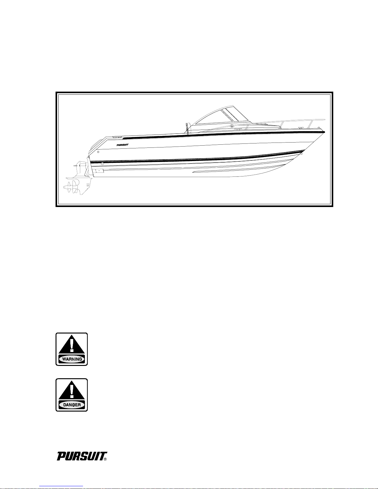
2260 DENALI

Dear Pursuit Denali Owner:
All of us at Pursuit are pleased that you have selected one of our products as your
boat. As I’m sure you’ve discovered during the selection and decision process,
your Pursuit has been designed, engineered and built with care and precision.
Please allow me to note my personal philosophy. When I started this company,
my goal was to provide you, our customer, with the finest quality boat available.
Everything we have achieved since that time has been with the same goal in
mind.
The information in this owner’s manual has been assembled to assist you with
obtaining maximum enjoyment with your Pursuit. Please read this manual
completely and always operate your boat safely and courteously.
Thank you for selecting a Pursuit Fishing Boat. We all wish you many years
of boating fun and safety.
Sincerely,
Leon R. Slikkers
Chief Executive Officer
2260 DENALI
i

THIS PAGE WAS LEFT BLANK
INTENTIONALLY
2260 DENALI
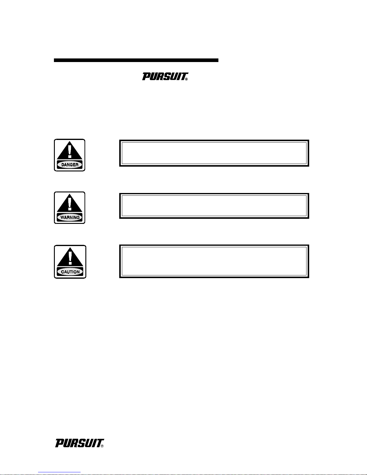
SAFETY INFORMATION
Your Denali Owner’s Manual has been written
to include a number of safety instructions to assure the safe
operation and maintenance of your boat. These instructions
are in the form of WARNING, CAUTION and DANGER
statements. The following definitions apply:
IMMEDIATE HAZARDS WHICH WILL RESULT IN
SEVERE PERSONAL INJURY OR DEATH.
HAZARDS OR UNSAFE PRACTICES WHICH COULD
RESULT IN SEVERE PERSONAL INJURY OR DEATH.
HAZARDS OR UNSAFE PRACTICES WHICH COULD
RESULT IN MINOR PERSONAL INJURY OR
PRODUCT AND PROPERTY DAMAGE.
All instructions given in this book are as seen from the stern
looking toward the bow, with starboard being to your right,
and port to your left. A glossary of boating terms is included.
IMPORTANT NOTE: Your boat uses internal combustion
engines and flammable fuel. Every precaution has been taken
by Pursuit Fishing Boats to reduce the risks associated with
possible injury and damage from fire or explosion, but your
own precaution and good maintenance procedures are necessary in order to enjoy safe operation of your boat.
2260 DENALI
ii

THIS PAGE WAS LEFT BLANK
INTENTIONALLY
2260 DENALI
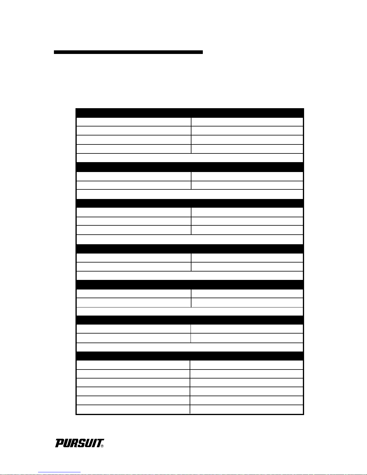
BOAT INFORMATION
Please fill out the following information section and leave it in your Pursuit
2260 Denali Owner’s Manual. This information will be important for you and
Pursuit service personnel to know, if and when you may need to call Pursuit
for technical assistance or service.
BOAT
MODEL:
PURCHASE DATE:
IGNITION KEYS #:
DRAFT:
ENGINE(S)
MAKE:
PORT SERIAL #:
TRANSMISSION(S) (Inboard)
MAKE: MODEL:
PORT SERIAL #:
RATIO:
HULL SERIAL #:
DELIVERY DATE:
REGISTRATION #:
WEIGHT:
MODEL:
STARBOARD SERIAL #:
STARBOARD SERIAL #:
MAKE: MODEL:
PORT SERIAL #:
STARBOARD SERIAL #:
PROPELLER(S)
OUTDRIVE(S) (Inboard/Outboard)
MAKE:
DIAMETER/PITCH:
BLADES:
OTHER:
TRAILER
MAKE:
SERIAL #:
MODEL:
GVRW:
DEALER PURSUIT
NAME:
DEALER/PHONE:
SALESMAN:
SERVICE MANAGER:
ADDRESS:
Pursuit Fishing Boats reserves the right to make changes and improvements in equipment, design and vendored
equipment items, at any time without notification.
PHONE:
REPRESENTATIVE:
ADDRESS:
2260 DENALI
iii

THIS PAGE WAS LEFT BLANK
INTENTIONALLY
2260 DENALI

IMPORTANT INFORMATION
Warranty and Warranty Registration Cards
The Denali Limited Warranty Statement is included with your boat. It has been written to be clearly
stated and easily understood. If you have any questions after reading the warranty, please contact
the Pursuit Customer Relations Department.
Pursuit, engine manufacturers, and the suppliers of major components maintain their own
manufacturer's warranty and service facilities. It is important that you properly complete the
warranty registration cards included with your boat and engine(s) and mail them back to the
manufacturer to register your ownership. This should be done within 15 days of the date of
purchase and before the boat is put into service. A form for recording this information is provided
at the beginning of this manual. This information will be important for you and service personnel
to know, if and when you may need service or technical information.
The boat warranty registration requires the Hull Identification Number “HIN” which is located
on the starboard side of the transom, just below the rubrail. The engine warranty registration
requires the engine serial number(s). Please refer to the engine owner's manual for the location of
the serial number(s).
IMPORTANT:
All boat manufacturers are required by the Federal Boat Safety Act of 1971 to notify first time
owners in the event any defect is discovered “which creates a substantial risk of personal injury to
the public.” It is essential that we have your warranty registration card complete with your
name and mailing address in our files so that we can comply with the law if it should become
necessary.
Product Changes
Pursuit is committed to the continuous improvement of our boats. As a result, some of the
equipment described in this manual or pictured in the catalog may change or no longer be available.
Pursuit reserves the right to change standard equipment, optional equipment and specifications without notice or obligation. If you have questions about the equipment on your Denali,
please contact the Pursuit Customer Relations Department.
Transferring the Warranty
For a transfer fee, S2 Yachts will extend warranty coverage to subsequent owners of Pursuit models
for the duration of the original warranty period. Please refer to the Denali Limited Warranty
Statement for the procedure to transfer the warranty.
To take advantage of this program, notification of the change of ownership, including the new
owner's name, address and telephone number together with the appropriate fee, must be sent to
Pursuit Fishing Boats, Customer Relations Department, 3901 St. Lucie Boulevard, Ft. Pierce,
Florida 34946, within 30 days of the date of resale.
2260 DENALI
iv

IMPOR TANT INFORMATION
S2 Yachts will confirm, in writing, that the transfer of the warranty has taken place. After which,
the transferee will be treated as the original purchaser as outlined in the Denali Limited Warranty
Statement.
Service
All warranty repairs must be performed by an authorized Pursuit dealer. Should a problem develop
that is related to faulty workmanship or materials, as stated in the Limited Warranty, you should
contact your Pursuit dealer to arrange for the necessary repair. If you are not near your dealer or
another authorized Pursuit dealer or the dealer fails to remedy the cause of the problem, then contact
the Pursuit Customer Relations Department within 15 days. It is the boat owner's responsibility
to deliver the boat to the dealer for warranty service.
v
2260 DENALI

OWNER'S/OPERATOR'S
RESPONSIBILITIES
Registration and Numbering
Federal law requires that all undocumented vessels equipped with propulsion machinery be
registered in the state of principal use. A certificate of number will be issued upon registering the
boat. These numbers must be displayed on your boat. The owner/operator of a boat must carry
a valid certificate of number whenever the boat is in use. When moved to a new state of principal
use, the certificate is valid for 60 days.
In order to be valid, the numbers must be installed to the proper specifications. Check with your
dealer or State Boating Authority for numbering requirements. The Coast Guard issues the
certificate of number in Alaska; all others are issued by the state.
Insurance
In most states the boat owner is legally responsible for damages or injuries he or someone else
operating the boat causes. Responsible boaters carry adequate liability and property damage
insurance for their boat. You should also protect the boat against physical damage and theft. Some
states have laws requiring minimum insurance coverage. Contact your dealer or State Boating
Authority for information on the insurance requirements in your boating area.
Reporting Boating Accidents
All boating accidents must be reported by the operator or owner of the boat to the proper marine
law enforcement authority for the state in which the accident occurred. Immediate notification is
required if a person dies or disappears as a result of a recreational boating accident.
If a person dies or there are injuries requiring more than first aid, a formal report must be filed within
48 hours.
A formal report must be made within 10 days for accidents involving more than $500.00 damage
or the complete loss of a boat.
A Boating Accident Report form is located near the back of this manual to assist you in reporting
an accident. If you need additional information regarding accident reporting, please call the
Boating Safety Hotline, 800-368-5647.
Education
If you are not an experienced boater, we recommend that the boat operator and other people that
normally accompany the operator, enroll in a boating safety course. Organizations such as the U.S.
Power Squadrons, United States Coast Guard Auxiliary, State Boating Authorities and the
American Red Cross offer excellent boating educational programs. These courses are worthwhile
even for experienced boaters to sharpen your skills or bring you up to date on current rules and
2260 DENALI
vi

OWNER'S/OPERA TOR'S
RESPONSIBILITIES
regulations. They can also help in providing local navigational information when moving to a new
boating area. Contact your dealer, State Boating Authority or the Boating Safety Hotline, 800368-5647 for further information on boating safety courses.
Required Equipment
U.S. Coast Guard regulations require certain equipment on each boat. The Coast Guard also sets
minimum safety standards for vessels and associated equipment. To meet these standards some of
the equipment must be Coast Guard approved. “Coast Guard Approved Equipment” has been
determined to be in compliance with USCG specifications and regulations relating to performance,
construction, or materials. The equipment requirements vary according to the length, type of boat,
and the propulsion system. Some of the Coast Guard equipment is described in the Safety
Equipment chapter of this manual. For a more detailed description, obtain “Federal Requirements
And Safety Tips For Recreational Boats” by contacting the Boating Safety Hotline 800-368-5647
or your local marine dealer or retailer and read the book “Sportfish, Cruisers and Yachts” included
with your boat.
Some state and local agencies impose similar equipment requirements on waters that do not fall
under Coast Guard jurisdiction. These agencies may also require additional equipment that is not
required by the Coast Guard. Your dealer or local boating authority can provide you with additional
information for the equipment requirements for your boating area.
vii
2260 DENALI

TABLE OF CONTENTS
Chapter 1: Propulsion System
1.1 General ....................................................................................1-1
1.2 Drive Systems ..........................................................................1-2
1.3 Engine Exhaust System .............................................................1-3
1.4 Engine Cooling System .............................................................1-3
1.5 Propellers.................................................................................1-4
1.6 Engine Instrumentation ..............................................................1-5
Chapter 2: Helm Control Systems
Page No.
2.1 General.................................................................................... 2-1
2.2 Engine Throttle and Shift Controls............................................. 2-1
2.3 Neutral Safety Switch............................................................... 2-2
2.4 Engine Stop Switch .................................................................. 2-2
2.5 Outdrive Power Tilt and Trim ................................................... 2-2
2.6 Steering System ....................................................................... 2-3
2.7 Trim Tabs................................................................................ 2-3
2.8 Control Systems Maintenance .................................................. 2-4
Chapter 3: Fuel System
3.1 General.................................................................................... 3-1
3.2 Inboard/Outboard Fuel System ................................................ 3-3
3.3 Fueling Instructions................................................................... 3-4
3.4 Fuel System Maintenance......................................................... 3-5
2260 DENALI
viii

T ABLE OF CONTENTS
Chapter 4: Electrical System
4.1 General ................................................................................... 4-1
4.2 12-Volt System ....................................................................... 4-1
4.3 Electrical System Maintenance ................................................. 4-4
Chapter 5: Freshwater System
5.1 General ................................................................................... 5-1
5.2 Freshwater System Operation .................................................. 5-1
5.3 Freshwater System Maintenance .............................................. 5-2
Page No.
Chapter 6: Raw W ater System
6.1 General ................................................................................... 6-1
6.2 High Pressure Washdown ........................................................ 6-2
6.3 Livewell................................................................................... 6-3
6.4 Raw Water System Maintenance ............................................. 6-4
Chapter 7: Drainage Systems
7.1 Cabin Sole and Cockpit Drainage ............................................ 7-1
7.2 Bilge Drainage ......................................................................... 7-2
7.3 Fishboxes/Coolers and Livewell Drains .................................... 7-3
7.4 Rope Locker Drain.................................................................. 7-3
7.5 Maintenance ............................................................................ 7-3
ix
2260 DENALI

T ABLE OF CONTENTS
Chapter 8: Ventilation
8.1 Cabin Ventilation ..................................................................... 8-1
8.2 Windshield Ventilation ............................................................. 8-1
8.3 Engine Compartment Ventilation .............................................. 8-2
8.4 Carbon Monoxide and Ventilation............................................ 8-3
8.5 Maintenance ............................................................................ 8-4
Chapter 9: Safety Equipment
9.1 General .................................................................................... 9-1
9.2 Engine Alarms .......................................................................... 9-1
9.3 Neutral Safety Switch ............................................................... 9-2
9.4 Engine Stop Switch .................................................................. 9-2
9.5 Required Safety Equipment....................................................... 9-2
9.6 Automatic Fire Extinguishing System ......................................... 9-5
9.7 Carbon Monoxide Monitoring System ...................................... 9-6
9.8 First Aid................................................................................... 9-7
9.9 Additional Safety Equipment..................................................... 9-8
9.10 Maximum Capacity Rating........................................................ 9-9
Page No.
Chapter 10: Operation
10.1 General .................................................................................... 10-1
10.2 Rules of the Road..................................................................... 10-1
10.3 Pre-Cruise System Check ........................................................ 10-3
10.4 Operating Your Boat................................................................ 10-4
10.5 Water Skiing ............................................................................ 10-7
10.6 F is hi ng ..................................................................................... 10-8
10.7 Grounding and Towing ............................................................. 10-8
10.8 Trailering Your Boat................................................................. 10-9
2260 DENALI
x

T ABLE OF CONTENTS
Chapter 11: Exterior Equipment
11.1 Deck ........................................................................................ 11-1
11.2 Hull .......................................................................................... 11-2
11.3 Cockpit Equipment ................................................................... 11-3
Chapter 12: Interior Equipment
12.1 Portable Head.......................................................................... 12-1
12.2 Cabin and V-Berth .................................................................. 12-2
12.3 Carbin Monoxide Detector...................................................... 12-2
Page No.
Chapter 13: Routine Maintenance
13.1 Exterior Hull and Deck.............................................................. 13-1
13.2 Upholstery, Canvas and Enclosures ........................................... 13-5
13.3 Cabin Iinterior........................................................................... 13-6
13.4 Bilge and Engine Compartment.................................................. 13-7
13.5 Drainage System ....................................................................... 13-8
Chapter 14: Seasonal Maintenance
14.1 Lay-up and Storage .................................................................. 14-1
14.2 Winterizing ................................................................................ 14-4
14.3 Recommissioning....................................................................... 14-5
xi
2260 DENALI

T ABLE OF CONTENTS
Chapter 15: Schematics
12-Volt Wiring Schematic..................................................................... 15-1
Battery Wiring ...................................................................................... 15-2
Steering System .................................................................................... 15-3
Fuel System.......................................................................................... 15-4
Raw Water System............................................................................... 15-5
Freshwater System ............................................................................... 15-6
Drainage System................................................................................... 15-7
Appendix A: Glossary of Terms .......................................................... A-1
Appendix B: Maintenance Log ............................................................ B-1
Appendix C: Boating Accident Report ................................................. C-1
2260 DENALI
xii

THIS PAGE WAS LEFT BLANK
INTENTIONALLY
2260 DENALI
Chapter 1:
PROPULSION SYSTEM
1.1 General
The 2260 Denali is designed to be powered with a single inboard/outboard engine and drive
system. Each manufacturer of the various inboard/outboard drive systems provides an owner’s
information manual with its product. It is important that you read the manual(s) very carefully and
become familiar with the proper care and operation of the engine and drive system. A warranty
registration card has been furnished with each new engine and can be located in the engine owner’s
manual. All information requested on this card should be filled out completely by the dealer and
purchaser and then returned to the respective engine manufacturer as soon as possible.
DO NOT ATTEMPT TO SERVICE ANY ENGINE OR DRIVE COMPONENT WITHOUT BEING
TOTALLY FAMILIAR WITH THE SAFE AND PROPER SERVICE PROCEDURES. CERTAIN
MOVING PARTS ARE EXPOSED AND CAN BE DANGEROUS TO SOMEONE UNFAMILIAR
WITH THE OPERATION AND FUNCTION OF THE EQUIPMENT.
DO NOT INHALE EXHAUST FUMES! EXHAUST CONTAINS CARBON MONOXIDE THAT IS
COLORLESS AND ODORLESS. CARBON MONOXIDE IS A DANGEROUS GAS THAT IS POTENTIALLY LETHAL.
2260 DENALI
1-1
USE ONLY CLEAN, DRY FUEL OF THE TYPE AND GRADE RECOMMENDED BY THE ENGINE MANUFACTURER. THE USE OF INCORRECT OR CONTAMINATED FUEL CAN
CAUSE ENGINE MALFUNCTION AND SERIOUS DAMAGE.
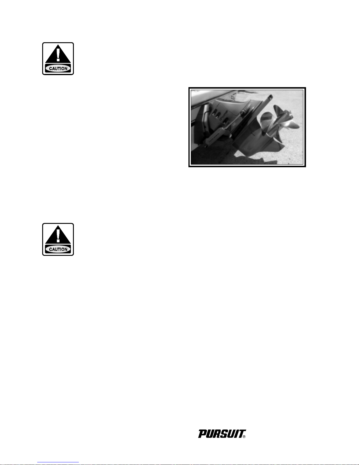
1.2 Drive Systems
The inboard engine is mounted in the stern and
coupled to a transom mounted outdrive which does
all shifting, steering, and propulsion functions. The
outdrive is supplied by the engine manufacturer and
has specific lubrication and maintenance requirements.
Proper engine alignment is very important. This
was done by the factory when the engine was
installed and should be checked at the 20 hour check
and annually thereafter. If you experience excessive
vibrations or suspect that the engine is out of alignment, please contact your Pursuit dealer.
ALWAYS RETURN THE ENGINE THROTTLE LEVER TO THE EXTREME LOW SPEED POSITION BEFORE SHIFTING. NEVER SHIFT THE UNIT WHILE ENGINE SPEED IS ABOVE
IDLE RPM.
Marine growth and galvanic corrosion is a concern if the boat is to be kept in saltwater. Marine
growth occurs when components are left in the water for extended periods and can cause poor
performance or permanent damage to the exposed components. The type of growth and how
quickly it occurs is relative to the water conditions in your boating area. Water temperature,
pollution, current, etc. can have an effect on marine growth. If the boat is to be left in saltwater,
the hull and outdrive must be protected with antifouling paint. It is extremely important that the
proper antifouling paint is used on each component. Contact your Pursuit dealer for information
on the proper paint to use in your area.
Outdrive and Propeller
Galvanic corrosion is the corrosion process occurring when different metals are submerged in an
electrolyte. Sea water is an electrolyte and submerged engine components must be properly
protected. Outdrives are equipped with sacrificial zinc anodes to prevent galvanic corrosion
problems. The zinc anodes must be monitored and replaced as necessary.
On some outdrives, the zinc anode may not provide an acceptable level of protection when a drive
is used in freshwater and a magnesium anode must be used. This condition is worsened with the
installation of the optional stainless steel propellers. A magnesium anode, when used for combined
operation in both fresh/saltwater, or water with a low salt content, will be used quicker and must
1-2
2260 DENALI
therefore be replaced more often. For recommendations regarding corrosion protection for the
engine or outdrive, please refer to the engine owner’s manual.
SOME OUTDRIVES REQUIRE SPECIAL ANODES FOR FRESHWATER AND A DIFFERENT
TYPE OF ANODE FOR SALTWATER. PLEASE CONTACT THE ENGINE MANUFACTURER OR YOUR PURSUIT DEALER FOR THE PROPER ANODE TO USE IN YOUR BOATING
AREA.
SOME BODIES OF FRESH AND SALTWATER CAN EXPERIENCE SEVERE CORROSION FOR
A VARIETY OF REASONS. IN THESE AREAS, STAINLESS STEEL PROPELLERS CAN
WORSEN THE PROBLEM AND MAY NOT BE DESIRABLE FOR USE ON STERNDRIVE
BOATS KEPT IN THE WATER.
DO NOT PAINT THE OUTDRIVE OR ALLOW THE OUTDRIVE TO COME IN CONTACT
WITH ANTIFOULING PAINTS DESIGNED FOR BOAT HULLS. MANY OF THESE PAINTS
CAN CAUSE SEVERE DAMAGE TO THE OUTDRIVE. CONTACT YOUR PURSUIT DEALER
OR ENGINE MANUFACTURER FOR INFORMATION ON THE PROPER PAINTING PROCEDURES.
1.3 Engine Exhaust System
Inboard/outboard engines use the exhaust system to relinquish exhaust gases and cooling water.
Engine exhaust exits the rear of the boat through the exhaust system. The system consists of engine
exhaust manifolds, exhaust hoses and the outdrive.
A periodic inspection of the hoses, exhaust hoses and related parts should be made to insure that
leaks, heat deterioration or damage has not resulted. Replace them as necessary. Refer to the engine
owner's manual for more information on the exhaust system in your Denali.
1.4 Engine Cooling System
All marine engines use surface water as a cooling medium. The cooling water enters the system
through a water intake in the outdrive and is expelled through the exhaust system. Water is pumped
through the water inlets, circulated through the engine block or heat exchanger, and relinquished
with the exhaust gases through the outdrive. The water pump uses a small impeller made of
synthetic rubber. The impeller and water pump cannot run dry for more than a few seconds.
NEVER RUN THE MOTOR WITHOUT WATER FLOWING TO THE WATER PUMP. SERIOUS DAMAGE TO THE WATER PUMP IMPELLER OR ENGINE COULD RESULT.
2260 DENALI
1-3
Note: If the boat is used in salt or badly polluted water, engines without freshwater cooling
should be flushed after each use. Refer to the engine owner’s manual for the proper
engine flushing procedure.
Freshwater Cooling (Optional)
Installation of “Freshwater Cooling” provides adequate engine cooling without exposing the
internal engine cooling system to the harmful effects of surface water. This system is optional with
gasoline stern drive engines on the 2260 Denali. The engine owner’s manual provides additional
information regarding service and maintenance of this equipment.
SHOULD AN ENGINE INTAKE OR AN EXHAUST OR COOLING HOSE RUPTURE, TURN
THE ENGINE OFF IMMEDIATELY. PROCEED UNDER TOW IF NECESSARY, TO A SERVICE FACILITY FOR APPROPRIATE REPAIRS. MAINTAIN A CLOSE VISUAL WATCH ON
THE PROBLEM HOSE AND THE BILGE WATER LEVEL.
1.5 Propellers
The propellers convert the engine’s power into thrust. They come in a variety of styles, diameters
and pitches. The one that will best suit the needs of your Denali will depend somewhat on your
application and expected average load. Propeller sizes are usually identified by two numbers
stamped on the prop in sequence. The 1st number in the sequence (example 14 x 21) is the diameter
of the propeller and the 2nd number is the pitch. Pitch is the theoretical distance traveled by the
propeller in each revolution. Always repair or replace a propeller immediately if it has been
damaged. A damaged and therefore out of balance propeller can cause vibration that can be felt
in the boat and could damage the outdrive gear assembly. Refer to the engine owner’s manual for
information on propeller removal and installation.
Note: Before changing propellers to correct boat performance problems, be sure other
factors such as engine tuning, bottom and running gear growth, etc. are not the
source of performance changes. Always be sure the load conditions are those
normally experienced, before changing propellers.
RUNNING AGROUND OR STRIKING AN UNDERWATER OBSTRUCTION CAN RESULT IN SERIOUS INJURY AND DAMAGE TO THE DRIVE SYSTEM OR BOAT. IF YOUR BOAT RUNS
AGROUND, EVALUATE THE DAMAGE THEN PROCEED AT LOW SPEED TO THE NEAREST SERVICE FACILITY AND HAVE AN IMMEDIATE INSPECTION MADE BEFORE FURTHER USE OF THE CRAFT. A DAMAGED BOAT CAN TAKE ON WATER. KEEP ALL
LIFE SAVING DEVICES CLOSE AT HAND WHILE DRIVING TO A DOCK AREA. IF THE
BOAT CANNOT BE IMMEDIATELY REMOVED FROM THE WATER, THOROUGHLY INSPECT THE BILGE AREA FOR LEAKS SO THAT THE BOAT DOES NOT SINK WHILE
MOORED.
1-4
2260 DENALI
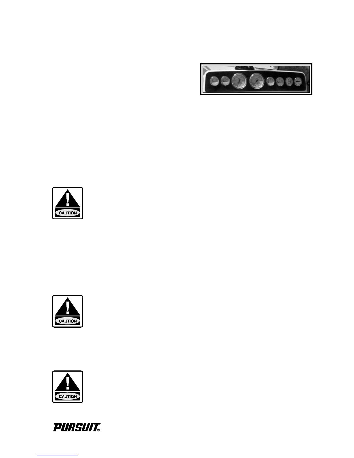
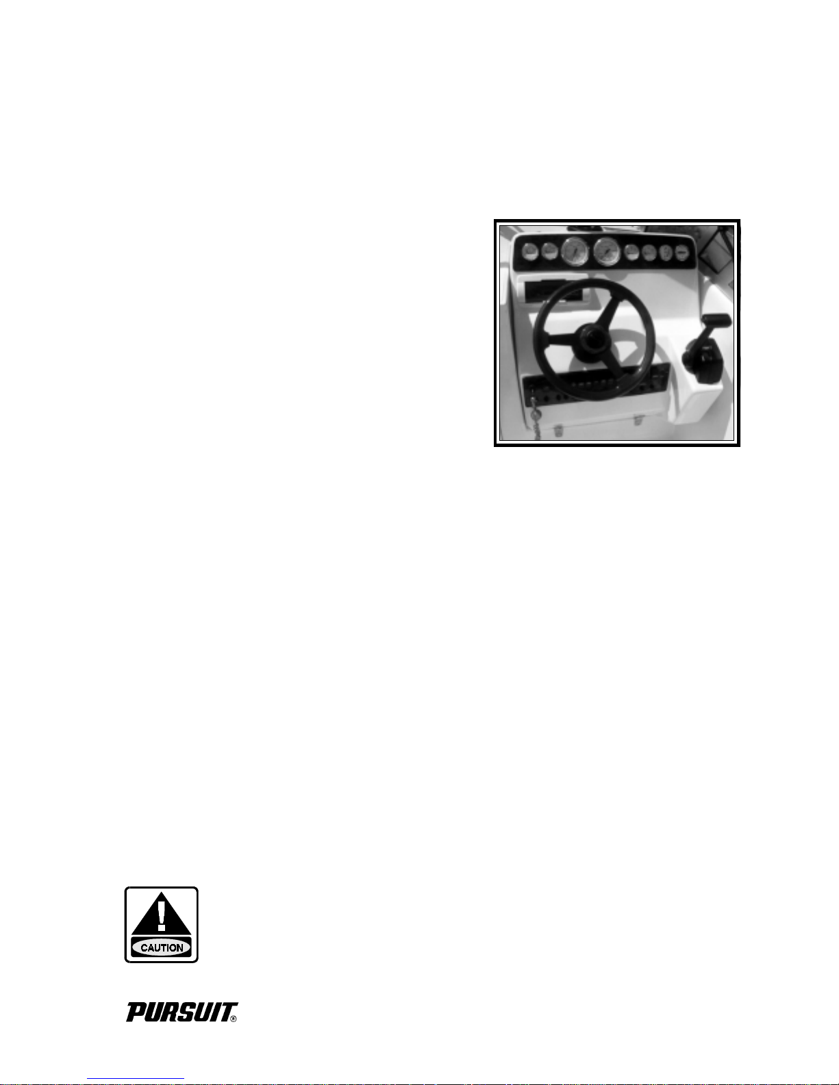
1.6 Engine Instrumentation
The helm station is equipped with a set of engine
instruments and/or alarms. These instruments allow
the pilot to monitor the engine’s operational conditions. Close observation of these instruments allows
the pilot to operate the engine at the most efficient
level and could save the engine from serious costly
damage. The instrumentation is unique to the type of
outdrive installed on your Denali. Some or all of the
following gauges may be present.
Tachometer
The tachometer displays the speed of the engine in revolutions per minute (RPM). This speed is
not the boat speed nor necessarily the speed of the propeller. The tachometer may not register zero
with the key in the “OFF” position.
NEVER EXCEED THE MAXIMUM RECOMMENDED OPERATION RPM OF THE ENGINE.
MAINTAINING MAXIMUM, OR CLOSE TO MAXIMUM RPM FOR EXTENDED PERIODS CAN
REDUCE THE LIFE OF THE ENGINE.
Instrument Panel
Speedometer
The speedometer indicates the speed of the boat in miles per hour.
Temperature Gauge
The temperature gauge shows the temperature of the engine cooling system. A sudden increase in
the temperature could indicate an obstructed water inlet or a water pump impeller failure.
CONTINUED OPERATION OF AN OVERHEATED ENGINE CAN RESULT IN ENGINE DAMAGE OR SEIZURE. IF AN UNUSUALLY HIGH TEMPERATURE READING OCCURS, SHUT
THE ENGINE OFF IMMEDIATELY. THEN INVESTIGATE AND CORRECT THE PROBLEM.
Oil Pressure Gauge
The oil pressure gauge monitors the engine lubrication system pressure. A drop in oil pressure is
a possible indication of oil pump problems or a leak.
OPERATION OF AN ENGINE WITH ABNORMALLY LOW, OR HIGH, OIL PRESSURE CAN
LEAD TO ENGINE DAMAGE AND POSSIBLE SEIZURE. HAVE THE ENGINE SERVICED
IMMEDIATELY UPON AN ABNORMAL OIL PRESSURE INDICATION.
2260 DENALI
1-5
Fuel Gauge
The fuel gauge indicates the amount of fuel in the fuel tank.
Voltmeter
The voltmeter displays the voltage for the battery and the charging system. The normal voltage is
11 to 12 volts with the engine off and 13 to 14.5 volts with the engine running.
Hour Meter
The hour meter keeps a record of the operating time for the engine. The hour meter is located in
the engine compartment.
Tilt/Trim Gauge
The tilt/trim gauge monitors the position of the outdrive. The upper range of the gauge indicates
the tilt, which is used for trailering and shallow water operation. The lower range indicates the trim
position. This is the range used to adjust the hull angle while operating your boat on plane. Please
refer to Chapter 2 and the engine owner's manual for more information on the operation of the
outdrive power tilt and trim.
Engine Alarms
Some inboard/outboard engines could be equipped with an audible alarm system mounted in the
helm area that monitors selected critical engine systems. The alarm will sound if one of these
systems begins to fail. Refer to the engine owner’s manual for information on the alarms installed
with your engine.
IF THE ENGINE ALARM SOUNDS, IMMEDIATELY RETURN THE THROTTLE TO IDLE AND
MOVE THE SHIFT CONTROL TO THE NEUTRAL POSITION. SHUT OFF THE ENGINE
UNTIL THE PROBLEM IS FOUND AND CORRECTED.
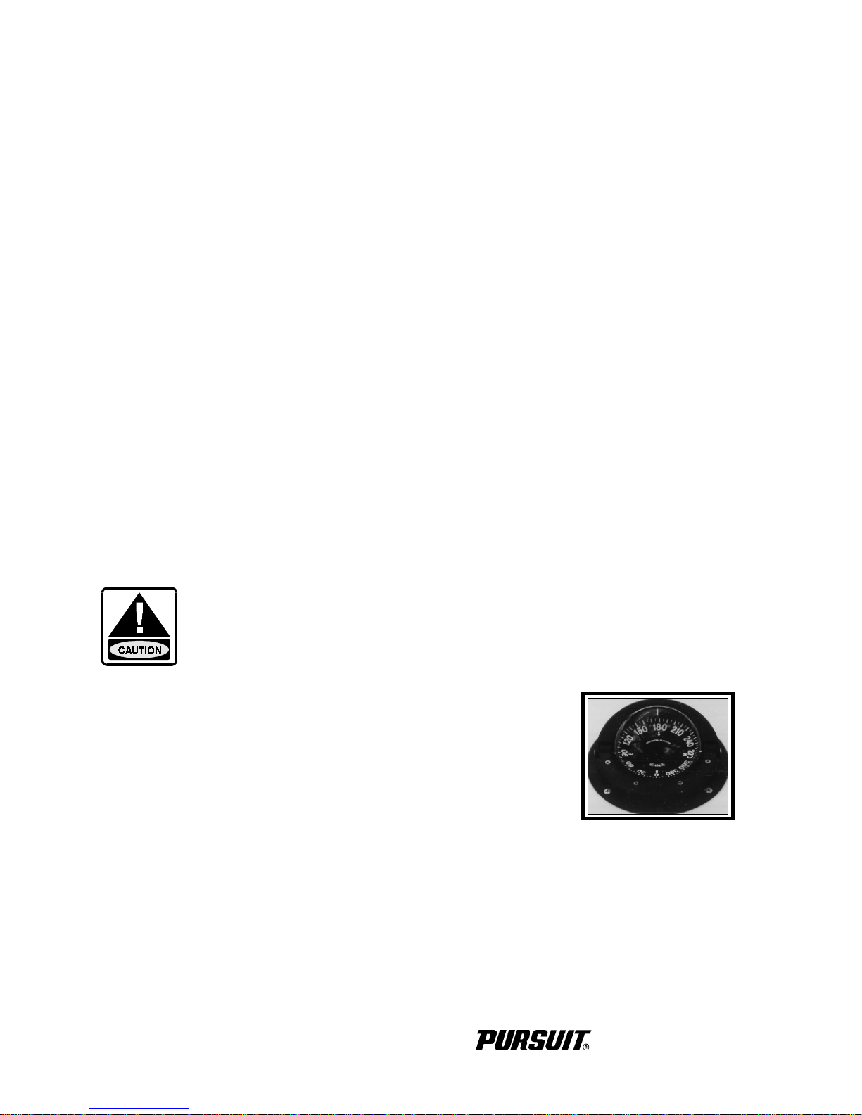
Compass
The compass is on top of the helm. To adjust the compass for your area,
read the instructions on “Compass Compensation” given to you in the
literature packet. The compass cannot be adjusted accurately at the
factory as it must be compensated for the influence of the electrical
equipment and electronics unique to your boat. Therefore, the compass
should be adjusted by a professional after the electronics and additional
electrical accessories are installed and before operating the boat.
Depth Gauge
The depth gauge indicates the depth of the water below the bottom of the boat.
Compass
1-6
2260 DENALI

Instruments Maintenance
Electrical protection for instruments and ignition circuitry is provided by a set of circuit breakers
located near the main battery switch. The ignition switch should be sprayed periodically with a
contact cleaner/lubricant. The ignition switch and all instruments, controls, etc. should be protected
from the weather when not in use. Excessive exposure can lead to gauge and ignition switch
difficulties.
2260 DENALI
1-7

THIS PAGE WAS LEFT BLANK
INTENTIONALLY
2260 DENALI
Chapter 2:
HELM CONTROL SYSTEMS
2.1 General
The helm controls consist of the following: engine throttle
and shift controls, the steering system, the outdrive tilt
and trim control, and the optional trim tab control switches.
These systems provide the operator with the ability to
control the direction and attitude of the boat from the
helm station.
Each manufacturer of the control components provides
an owner’s manual with its product. It is important that
you read the manuals and become familiar with the
proper care and operation of the control systems.
Helm
2.2 Engine Throttle and Shift Controls
The shift and throttle control on your boat may vary depending on the engine used. The following
control description is typical of most inboard/outboard remote controls. Refer to the engine or
control manual for specific information on the control installed on your Denali.
The engine throttle and shift control system consists of three major components: the control handle,
the throttle cable, and the shift cable. The cables are all the push-pull type. Two cables are required.
One connects the remote throttle control to the engine and the other connects the remote shift control
to the outdrive shift linkage.
The helm on your Denali is designed for a binnacle style control with a single lever that operates
as a gear shift and a throttle. General operation will include a position for neutral (straight up and
down), a forward position (the 1st detent forward of neutral), and a reverse position (the 1st detent
aft of neutral). Advancing the control lever beyond the shift range advances the throttle in forward
or reverse. Each control is equipped with a means of permitting the engine to be operated at a higher
than idle RPM while in neutral for cold starting and warm-up purposes.
ALWAYS RETURN THE ENGINE THROTTLE LEVER TO THE EXTREME LOW SPEED POSITION BEFORE SHIFTING. NEVER SHIFT THE UNIT WHILE ENGINE SPEED IS ABOVE
IDLE RPM.
2260 DENALI
2-1

2.3 Neutral Safety Switch
Every control system has a neutral safety switch incorporated into it. This device prohibits the
engine from being started while the shift lever is in any position other than the neutral position. If
the engine will not start, slight movement of the shift lever may be necessary to locate the neutral
position and disengage the safety cutout switch. Control or cable adjustments may be required to
correct this condition should it persist. See your Pursuit dealer for necessary control and cable
adjustments.
The neutral safety switch should be tested periodically to insure that it is operating properly. To
test the neutral safety switch, make sure the outdrive is tilted down and move the shift lever to the
forward position. Make sure the control lever is not advanced past the idle position. Activate the
starter for the engine. The starter should not engage. Repeat this test with the shift lever in reverse
and the engine throttle at idle. Again, the starter should not engage. If the starter engages with the
shift control in any position other than the neutral position, then the neutral safety switch is not
functioning properly and you should contact your dealer and have the neutral safety switch repaired
before using your boat. If the engine starts in gear during this test, immediately move the control
lever to the neutral position. Turn the engine off and have the problem corrected by a qualified
marine mechanic before using the boat.
2.4 Engine Stop Switch
Your Denali is equipped with a engine stop switch and lanyard. When the
lanyard is pulled it will engage the switch and shut off the engine. We
strongly recommend that the lanyard be attached to the driver whenever the
engine is running. If the engine will not start, it could be because the lanyard
is not properly inserted into the engine stop switch. Always make sure the
lanyard is properly attached to the engine stop switch before attempting to
start the engine.
2.5 Outdrive Power Tilt and Trim
All inboard/outboard drive systems have a tilt and trim feature
for the outdrive. This allows the operator to control the position
of the outdrive from the helm. Moving the outdrive closer to
the boat transom is called trimming “in” or “down”. Moving
the outdrive further away from the boat transom is called
trimming “out” or “up”. In most cases, the boat will run best
with the drive unit adjusted so the hull will run at a 3 to 5 degree
angle to the water.
Outdrive Trim Switch
Engine Stop Switch
2-2
2260 DENALI
The term “trim” generally refers to the adjustment of the outdrive within the first 20o range of travel.
This is the range used while operating your boat on plane. The term “tilt” is generally used when
referring to adjusting the outdrive further up for shallow water operation or trailering. For
information on the proper use and maintenance of the power tilt and trim, please refer to the engine
owner's manual.
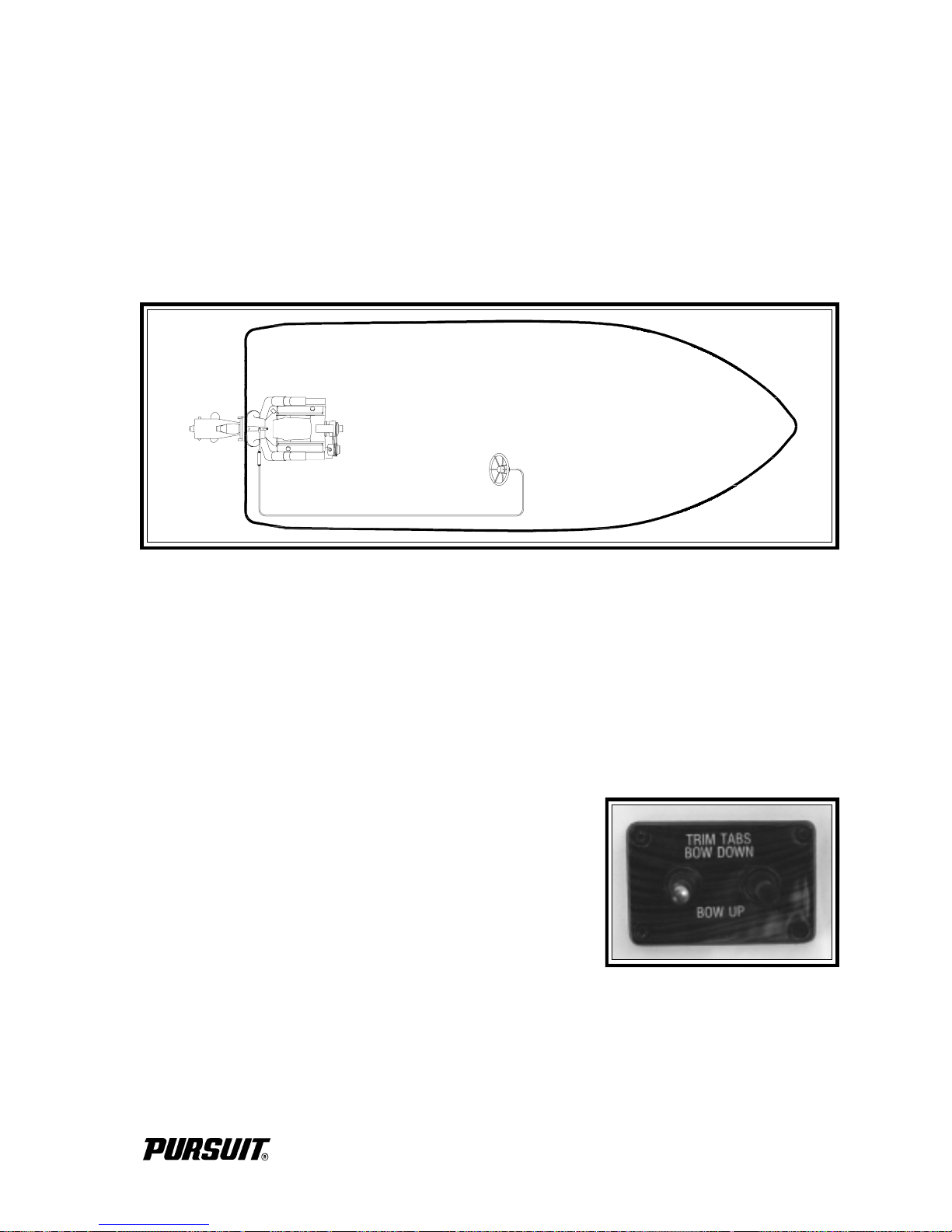
2.6 Steering System
Steering System
Your Denali is equipped with a power assisted cable steering system. Turning the wheel moves
the gears in the helm, pushing or pulling the cable assembly and turning the outdrive. An engine
driven power steering pump and cylinder assist the cable steering and reduces the effort required
to turn the boat. Please refer to the engine owner's manual for information on the power steering
system.
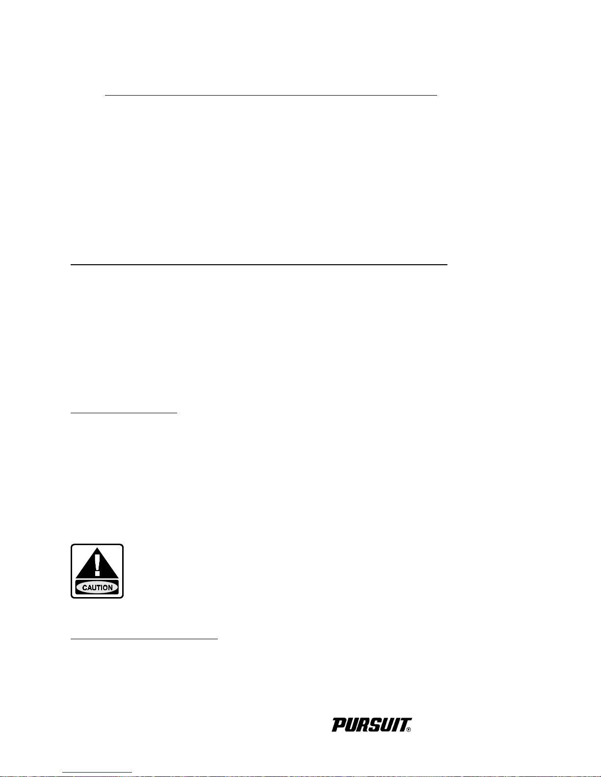
2.7 T rim Tabs (Optional)
The 2260 Denali uses a dual toggle switch to control the trim
tabs. The switch is labeled and controls bow up and down
movements. It also controls starboard and port up and down
movements. Bow up and bow down will control the hull
planing attitude while port and starboard up and down provides
control for the hull listing.
Before leaving the dock, make sure that the tabs are in the full
UP position by holding the control in the bow up position for
ten (10) seconds.
Trim Tab Switch
Always establish the intended heading and cruise speed before attempting to adjust the hull attitude
with the trim tabs. After stabilizing speed and direction, move the trim tabs to achieve a level side
to side running attitude being careful not to over trim.
2260 DENALI
2-3
After depressing a trim tab switch, always wait a few seconds for the change in trim plane to take
effect. Avoid depressing the switch while awaiting the trim plane reaction. By the time the
effect is noticeable the trim tab will have moved too far and thus the boat will be in an
overcompensated position.
When running at a speed that will result in the boat falling off plane, lowering the tabs slightly, bow
down, will improve the running angle and operating efficiency. Too much bow down tabs can
reduce operating efficiency and cause substantial steering and handling difficulties.
Be extremely careful when operating in a following sea. The effect of trim tabs is amplified under
such conditions. Steering and handling difficulties can result from improper trim tab usage,
particularly in a following sea. Always raise the tabs to the full bow up position in these conditions.
When running at high speeds be sure that the tabs are in the full UP position. Only enough
trim plane action should be used to compensate for any listing. Trim tabs are extremely sensitive
at high speeds. Adjust for this and be prepared to slow down if difficulties arise.
When running into a chop, a slight bow down attitude will improve the ride. Be careful not to over
trim. Handling difficulties may result.
2.8 Control Systems Maintenance
Control Maintenance
Periodic inspection of the control systems and all connections should be made. Signs of rust,
corrosion, wear, or other deterioration should be serviced immediately. Generally, periodic
lubrication of all moving parts and connections with a light waterproof grease is in order.
Lubrication should be performed as often as necessary to keep the system operating smoothly.
Control system adjustments may become necessary. If adjustment becomes necessary, see your
Pursuit dealer.
DO NOT ATTEMPT CONTROL ADJUSTMENTS UNLESS YOU ARE FAMILIAR WITH SERVICING CONTROL SYSTEM PROCEDURES. CONTROL MISADJUSTMENT CAN CAUSE LOSS
OF CONTROL AND SEVERE ENGINE OR OUTDRIVE DAMAGE.
Steering System Maintenance
A periodic inspection of all steering hoses, linkage and helm assemblies should be made. Signs of
corrosion, cracking, loosening of fastenings, excessive wear, or deterioration should be immediately corrected. Failure to do so could lead to steering system failure that would result in loss of
control.
2-4
2260 DENALI
 Loading...