

Page 1
1
User Guide GB
UFH - RF Analog thermostat 4-13
Guide d’utilisation F
UFH - RF Thermostat analogique 14-23
Bedienungsanleitung D
Analog Raumthermostat Funk 24-33
Gebruikshandleiding Nl
RF Analoge thermostaat 34-43
Instrukcja Użytkowania Pl
UFH – RF Termostat Analogowy 44-53
Bezprzewodowy
Manualul utilizatorului RO
Termostat analogic UFH - RF 54-63
Analog Basic RF
Page 2

2
Page 3

3
Page 4
4
Installation and Operation Manual
IMPORTANT!
Before starting work the installer should carefully read
this Installation & Operation Manual, and make sure all
instructions contained therein are understood and
observed.
- The thermostat should be mounted, operated and
maintained by specially trained personnel only.
Personnel in the course of training are only allowed to
handle the product under the supervision of an
experienced fitter. Subject to observation of the above
terms, the manufacture shall assume the liability for the
equipment as provided by legal stipulations.
- All instructions in this Installation & Operation manual
should be observed when working with the controller.
Any other application shall not comply with the
regulations. The manufacturer shall not be liable in
case of incompetent use of the control. Any
modifications and amendments are not allowed for
safety reasons. The maintenance may be performed by
service shops approved by the manufacturer only.
- The functionality of the controller depends on the
model and equipment. This installation leaflet is part of
the product and has to be obtained.
APPLICATION
- The UFH thermostat is developed to control and
manage actuators mounting on the manifold.
- The thermostat is normally used in conjunction with a
complete connecting box “UFH-MASTER” with or
without “Heating & Cooling module” to connect all
electrical & hydraulic components of the installation like
a circulation pump, actuators...
- The controllers have been designed for use in
residential rooms, office spaces and industrial facilities.
Verify that the installation complies with existing
regulations before operation to ensure proper use of
the installation.
Page 5
5
SAFETY INSTRUCTIONS
Before starting work disconnect power supply!
- All installation and wiring work related to the controller
must be carried out only when de-energized. The
appliance should be connected and commissioned by
qualified personnel only. Make sure to adhere to valid
safety regulations.
- The connecting boxes are neither splash- nor dripproof. Therefore, they must be mounted at a dry place.
- Do not interchange the connections of the sensors,
actuators and the 230V connections under any
circumstances!
Interchanging these connections may result in life
endangering electrical hazards or the destruction of
the appliance and the connected sensors and other
appliances.
Page 6
6
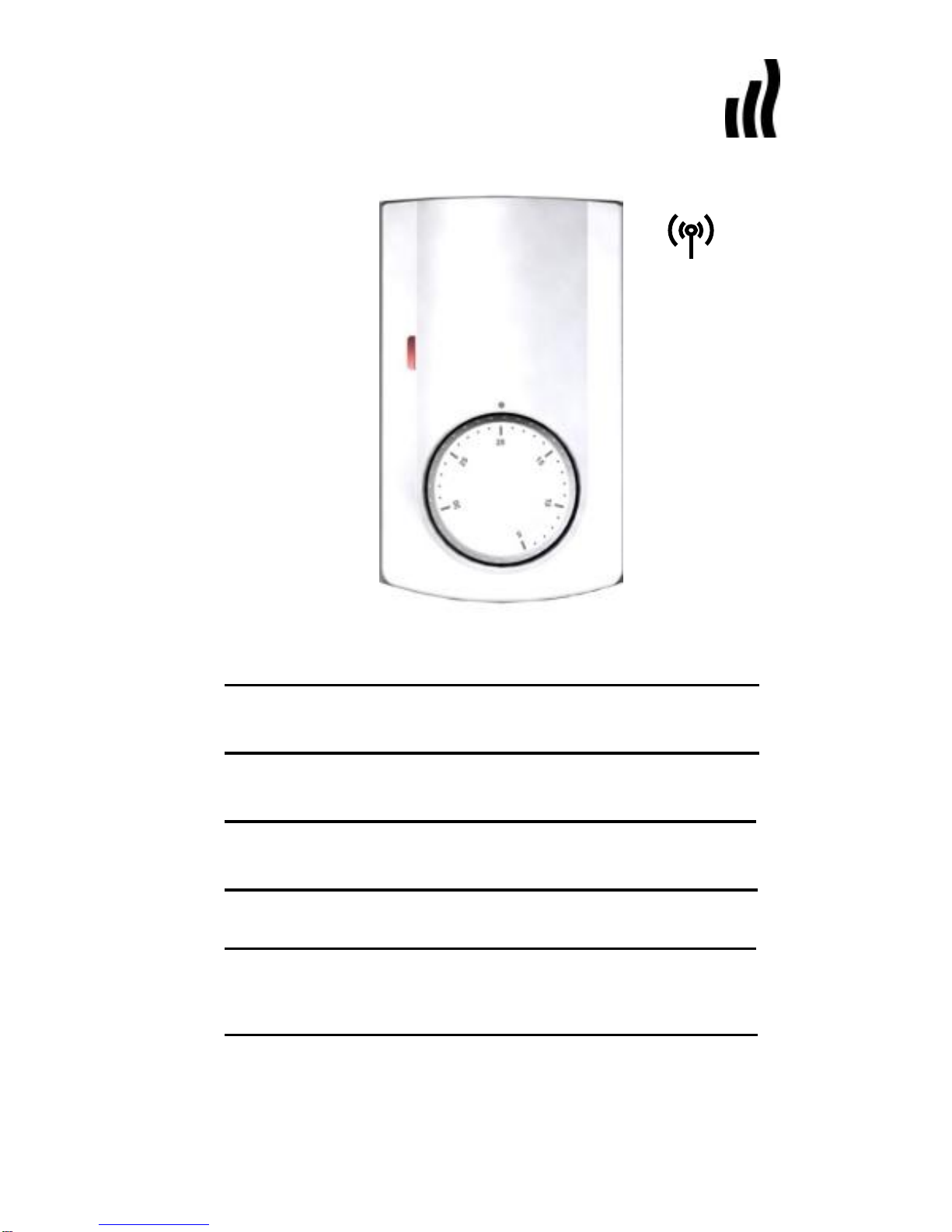
1 User Guide
UFH - RF Analog thermostat
Analog wireless (RF 868MHz) thermostat specially
designed to control your Under Floor Heating and
cooling managed by actuator.
- Wall mounting with table support.
- 2 AAA batteries.
2 Technical characteristics
Measured temperature
precision
0.1°C
Operating temperature
0°C - 50°C
Setting temperature
range
5°C - 30°C
Regulation
characteristics
Proportional Integral
(PWM)
2°C with 15min cycle
Electrical Protection
Class II - IP30
Power Supply
Battery operated life
2 x 1,5V (AAA)
~ 2 years with
ALKALINE type.
Radio frequency
868 MHz, <10mW.
certifications
EN 300220-1, -2
EN 301489-1, -3
Software version
1.x x
Page 7
7
3 Presentation
LED Indicator
Green Flashes: Radio frequency transmission.
Red: View of the regulating point during
adjustment.
4 How to use your thermostat
OFF mode: (Manual mode)
Use this mode if you want to stop the Heating or
Cooling function in the room.
Simple installation without main zone programmer:
The antifreeze temperature (7°C) will be maintained in
the room all the time.
Installation with main zone programmer: (with or
without Cooling function)
- In heating mode: (Winter)
The antifreeze temperature (7°C) will be maintained in
the room all the time.
- In cooling mode: (Summer)
The thermostat will be switched Off.
REDUCED operating mode: (Manual mode)
The reduced temperature will be followed all the time in
accordance with these descriptions:
Simple installation without main zone programmer:
The reduced temperature will be followed all the time.
(Setting temperature -2°C)
Page 8
8
Installation with main zone programmer: (with or
without Cooling function)
The reduced temperature will be followed as described
below:
- In heating mode: (Winter)
The reduced temperature will be the setting
temperature minus 2°C.
- In cooling mode: (Summer)
You can adjust the reduced setting temperature only
on the main zone programmer
(Check the leaflet of main zone programmer for more
information)
AUTOMATIC or COMFORT operating mode:
In this mode your thermostat will follow the program
(Comfort or reduced) and order (Heating, cooling, Anti
freeze, holiday…) of the main zone programmer if
installed.
Simple installation without main zone programmer:
The comfort temperature will be followed all the time.
Installation with main zone programmer: (with or
without Cooling function)
- In heating mode: (Winter)
The setting temperature adjusted on the thermostat will
be followed all the time.
- In cooling mode: (Summer)
You can adjust the comfort setting temperature only on
the main zone programmer
(Check the leaflet of main zone programmer for more
information)
Page 9
9
5 How to learn your RF thermostat with
the RF receiver
First of all, switch the button mode of the
thermostat in OFF position .
To learn (*) the RF thermostat with the receiver
you must put the receiver in “RF init” mode
(Please refer to the receiver leaflet).
Once, on the thermostat switch the button mode
on “Automatic” position .
o The thermostat will send now the RF signal to the
receiver. Check on the receiver the good
configuration.
o If the RF learning is not made correctly, check the
installation (antenna connection, supply voltage...)
o If the RF learning between the thermostat and the
receiver is good, put your thermostat in the off
mode .
o On the receiver you can exit the “RF init” mode or
configure another thermostat. (Please refer to the
receiver leaflet for this)
Now you can check the RF distance, go to the
room which must be regulated. Put your
thermostat on the final position (On the wall
support or on the table support), then put the
thermostat on the Automatic mode (setting
temperature 30°C). Close the door and go to the
receiver to check if the new status of the
thermostat has received.
Page 10

10
o If it’s good, adjust your setting temperature as
you want.
o If it’s not good, check the installation (Antenna
position, distance...)
* To make the installation easier it will be better to have
the thermostat near to the receiver in learning mode.
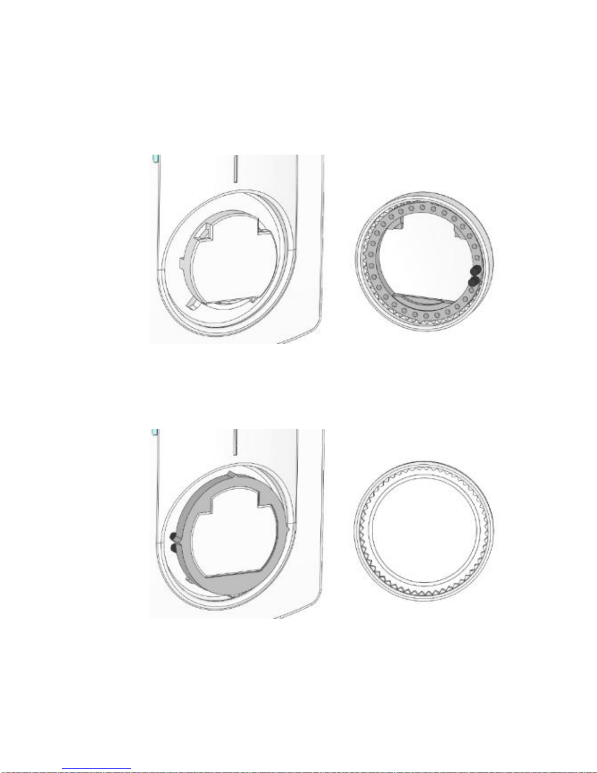
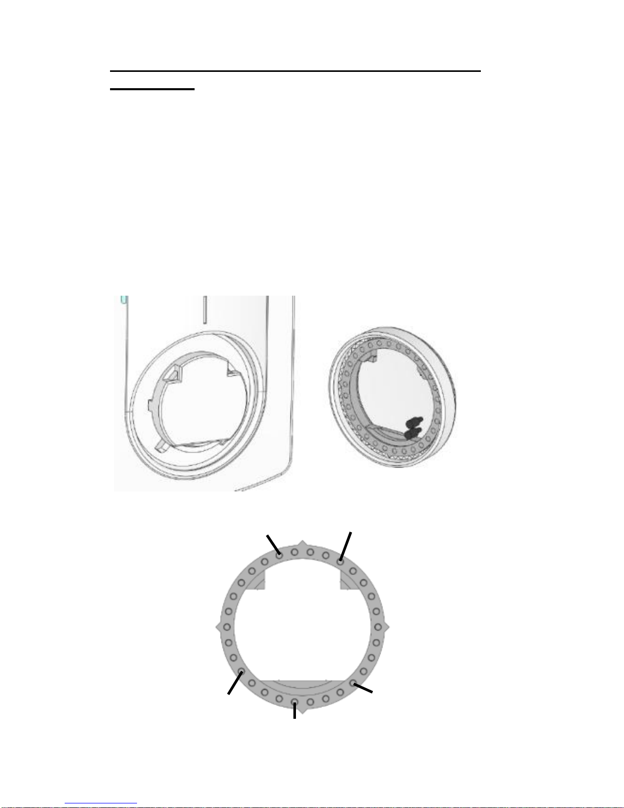
6 How to caliber and limit the setting
range.
If your thermostat needs to calibrated, make these
operations:
1. Put a thermometer in the middle of the room at
1.5 Meter distance of the floor.
2. Wait 1 hour to be sure that your thermostat shows
the correct temperature.
3. Remove the setting button by pressing gently
outwards with a narrow screwdriver between the
button and the cover. (pay attention to avoid
setting button rotation)
4. Remove the internal wheel from the button. (in
grey Figure 1)
5. Put the internal wheel alone on the thermostat.
(Figure 2)
6. You can now put the setting button on the
thermostat, while marking corresponds real room
temperature (showed by the thermometer) and
thermostat indexer.
Page 11
11
Fig. 1
Fig. 2
Page 12
12
If your thermostat needs to be limited, make these
operations:
1. Set the setting button on the middle of the new
setting range.
2. Remove the setting button by pressing gently
outwards with a narrow screwdriver between the
button and the cover.
3. Remove the dial pins and put in the desired holes
to limit the setting range of the thermostat. (Figure
3 et 4)
4. You can now put the setting button on the
thermostat.
Fig
3
Fig 4
20°C 25°C
Max
Limitation
Min
Limitation
20°C 10°C
15°C
Page 13

13
7 Notes
____________________________________________
____________________________________________
____________________________________________
____________________________________________
____________________________________________
____________________________________________
____________________________________________
____________________________________________
____________________________________________
____________________________________________
____________________________________________
____________________________________________
____________________________________________
____________________________________________
____________________________________________
____________________________________________
____________________________________________
____________________________________________
____________________________________________
____________________________________________
____________________________________________
____________________________________________
____________________________________________
____________________________________________
____________________________________________
____________________________________________
____________________________________________
____________________________________________
____________________________________________
____________________________________________
____________________________________________
____________________________________________
____________________________________________
____________________________________________
____________________________________________
____________________________________________
Page 14
14
Manuel d’utilisation et d’installation
IMPORTANT!
- Avant de commencer les travaux, le monteur doit lire,
comprendre et observer les présentes instructions de
montage et de service.
- Seul un spécialiste en la matière est autorisé à
effectuer le montage, le réglage et la maintenance
d’une régulation plancher type UFH. Un monteur en
formation ne peut réaliser de travaux sur l'appareil que
sous la surveillance d'un expert. La responsabilité du
fabricant conformément aux dispositions légales
s'applique uniquement dans le cas du respect des
conditions précitées.
- Veuillez observer l'ensemble des instructions de
montage et de service lors de l'utilisation du
programmateur de zones. Toute utilisation autre n'est
pas conforme. Le fabricant ne répond pas des
dommages occasionnés par une utilisation abusive de
la régulation. Pour des raisons de sécurité, aucune
transformation ou modification n'est admise. Seuls les
ateliers de réparation désignés par le fabricant sont
habilités à réparer la station solaire.
- Le contenu de la livraison de l'appareil varie selon le
modèle et l'équipement. Sous réserve de modifications
techniques !
Il est recommandé que l’installateur et l’utilisateur
prenne connaissance de l’intégralité de la notice, avant
de procéder à l’installation du matériel.
APPLICATION
- Le thermostat a été développé spécialement pour le
contrôle et la gestion d’électrovannes montées sur les
collecteurs de plancher (nourrisses).
- Le thermostat est normalement utilisé en conjonction
avec un «MASTER-UFH» avec ou sans module
«CHAUD / FROID», ils permettront les connections de
tous les composants électriques & hydrauliques de
Page 15

15
votre installation. (Circulateur, électrovannes,
thermostats)
Le module de régulation a été étudié pour un
fonctionnement dans un environnement résidentiel,
bureaux ou en équipement industriel.
Il est recommandé d’installer ce thermostat selon les
règles de l’art le tout en respectant les législations en
vigueur.
INSTRUCTION DE SECURITE
Veillez toujours à déconnecter l’alimentation avant
le montage ou la manipulation!
Toute installation ou raccordement électrique sur le
module doit être réalisé dans des conditions de
sécurité. Le module devra être raccordé et manipulé
par du personnel qualifié. Veuillez respecter les
législations de sécurité en vigueur, en particulier NF
C15-100 (Normes d’installation ≤ 1000 VAC). Les
boîtes de connexions ne sont pas étanches aux
éclaboussures ou aux projections d’eau. Il doit donc
être monté dans un endroit sec.
Prêtez une attention particulière lors du câblage, n’inter
-changez jamais les connections des sondes avec les
connections de puissance (230VAC), ceci pourrait
provoquer des dommages électriques voire la
destruction des sondes ou la régulation.
Sujet à modification sans avis préalable!
Page 16
16
1 Guide d’utilisation
UFH - RF Thermostat analogique
Thermostat analogique radiofréquence (RF 868MHz)
spécialement conçu pour la régulation de plancher
chauffant et rafraichissant hydraulique géré par
électrovanne thermique.
- Support pour fixation murale ou sur pied.
- 2 piles 1,5V AAA .
2 Caractéristiques techniques
Précision de mesure
0.1°C
Température de
fonctionnement
0°C - 50°C
Plage de réglage
5°C - 30°C
Caractéristiques de
régulation
Bande proportionnelle
ajustable (PWM)
Protection
Class II - IP30
Alimentation
Autonomie
2 x 1,5V (AAA)
~ 2 ans avec des piles type
Alcaline
Fréquences Radio
868 MHz, <10mW.
certifications
EN 300220-1, -2
EN 301489-1, -3
Version logiciel
1.x x
Page 17
17
3 Présentation
Voyant d’état
Clignotement vert: Transmission de signal Radio
Fréquence.
Rouge : Visualisation du point de régulation
pendant le réglage de la consigne.
4 Comment utiliser votre thermostat
Mode Arrêt: (Mode manuel)
Utilisez ce mode si vous désirez mettre votre
installation en Arrêt.
Installation simple sans centrale de
programmation:
La température de hors gel (7°C) sera maintenue
indéfiniment.
Installation avec centrale de programmation: (avec
ou sans fonction Chaud / Froid)
- En mode Chauffage : (Hiver)
La température de hors gel (7°C) sera maintenue
indéfiniment.
- En mode rafraichissement : (Eté)
La zone gérée par ce thermostat sera mise en arrêt.
REDUCED operating mode: (Manual mode)
La température réduite (ECO) sera suivie de la
manière suivante:
Page 18
18
Installation simple sans centrale de
programmation:
La température réduite (ECO) sera maintenue
indéfiniment. (Température ajustée sur le thermostat 2°C)
Installation avec centrale de programmation: (avec
ou sans fonction Chaud / Froid)
- En mode Chauffage : (Hiver)
La température réduite (ECO) sera maintenue
indéfiniment. (Température ajustée sur le thermostat 2°C)
- En mode rafraichissement : (Eté)
Vous pourrez ajuster la consigne réduite (ECO) pour le
mode froid uniquement sur la centrale de
programmation (reportez vous à la notice de la centrale
pour plus d’information)
Mode Automatique ou Confort:
Si une centrale de programmation est installée le
thermostat suivra les ordres envoyés par celle-ci, les
programmes (Jour/Nuit) ainsi que les modes de
fonctionnement (Chaud, Froid, Hors Gel, vacances...).
Installation simple sans centrale de
programmation:
La température de confort sera maintenue
indéfiniment.
Installation avec centrale de programmation: (avec
ou sans fonction Chaud / Froid)
- En mode Chauffage : (Hiver)
La température de confort ajustée sur le thermostat
sera maintenue indéfiniment
- En mode rafraichissement : (Eté)
Vous pourrez ajuster la consigne de confort pour le
mode froid uniquement sur la centrale de
programmation (reportez vous à la notice de la centrale
pour plus d’information)
Page 19
19
5 Comment appairer votre thermostat
avec votre récepteur
Tout d’abord positionner l’interrupteur de mode de
votre thermostat sur la position .
Ensuite, mettez votre récepteur en mode “RF init”.
(Reportez vous à la notice du récepteur ou de la
centrale de programmation pour cette opération)
Sur le thermostat, basculez l’interrupteur de mode
sur la position “Automatique” .
Le thermostat envoie maintenant le signal de
configuration RF au récepteur, vérifiez sur le
récepteur la bonne réception du signal.
o Si l’appairage RF n’a pas réussi, vérifiez
l’installation (connexion de l’antenne, batteries du
thermostat…) et répétez l’étape précédente.
o Si l’appairage entre le thermostat et le récepteur
s’est correctement passé, sur le thermostat
déplacez l’interrupteur de mode sur , pour ne
pas gêner les prochaines configurations RF.
Sur le récepteur, si vous n’avez plus de
thermostats à configurer vous pouvez quitter le
mode “RF init”.
Vous pouvez maintenant faire un test de portée pour
être sûr de l’installation.
Dans la pièce où doit se trouver le thermostat,
placez le à l’endroit où il sera positionné plus tard
(sur un meuble ou fixé au mur). Réglez la consigne
courante sur la position Maxi « 30°C », Fermez les
portes et allez vérifier la bonne réception du
nouveau statut sur le récepteur.
o Si le récepteur a correctement reçu le signal
(consigne à 30°C), l’installation est Ok.
Page 20

20
o Si le récepteur n’a pas correctement reçu
l’information, il se peut que vous soyez en
limite de portée, essayez alors de déplacer
l’antenne RF, le thermostat…
* Pour une installation plus rapide et maitrisée il est
préférable d’avoir le thermostat proche du récepteur en
appairage.
6 Comment calibrer et limiter la plage
de réglage.
Procédez de la manière suivante pour calibrer votre
thermostat :
1. Tout d’abord, placez un thermomètre au milieu de
la pièce à une hauteur d’environ 1,5 mètre du sol.
2. Attendre environ 1 heure pour que la valeur
affichée sur le thermomètre soit correcte. (temps
de stabilisation)
3. Tirez le bouton de réglage vers vous en faisant
délicatement levier avec un tournevis étroit entre
la face avant et le bouton (attention à ne pas faire
tourner le bouton).
4. Retirez ensuite la couronne interne. (photo 1)
5. Repositionnez la couronne interne sur le
thermostat. (photo 2)
6. Vous pouvez maintenant remettre le bouton de
réglage en place, en faisant coïncider la
température lue sur le thermomètre avec
l’indexeur du thermostat.
Page 21

21
Fig. 1
Fig. 2
Page 22

22
Procéder de la manière suivante pour borner la
plage de réglage de votre thermostat.
1. Positionnez le bouton de réglage au milieu de la
plage désirée
Exemple : vous désirez réduire la plage de
réglage entre 15 et 25°C =>
Positionnez votre bouton sur 20°C.
2. Tirez le bouton de réglage vers vous en faisant
délicatement levier avec un tournevis étroit entre
la face avant et le bouton.
3. Positionnez le bouton de réglage au milieu de la
plage désirée.
4. Retirez alors les pions de réglage et positionnez-
les sur la nouvelle plage de réglage. (photos a et
b)
5. Vous pouvez maintenant remettre le bouton de
réglage en place.
Fig 3
Fig 4
20°C 10°C
15°C
20°C 25°C
Max
Limitation
Min
Limitation
Page 23

23
7 Notes
____________________________________________
____________________________________________
____________________________________________
____________________________________________
____________________________________________
____________________________________________
____________________________________________
____________________________________________
____________________________________________
____________________________________________
____________________________________________
____________________________________________
____________________________________________
____________________________________________
____________________________________________
____________________________________________
____________________________________________
____________________________________________
____________________________________________
____________________________________________
____________________________________________
____________________________________________
____________________________________________
____________________________________________
____________________________________________
____________________________________________
____________________________________________
____________________________________________
____________________________________________
____________________________________________
____________________________________________
____________________________________________
____________________________________________
____________________________________________
____________________________________________
____________________________________________
Page 24

24
Installations- und Bedienungsanleitung
Wichtig!!
Bevor Sie mit der Installation beginnen, sollten sie sich
die Installations- und Bedienungsanleitung sorgfältig
durchlesen und unbedingt die nachfolgenden Punkte
beachten:
- Der Raumthermostat darf nur von Fachpersonal
oder unter deren Aufsicht installiert,
angeschlossen und konfiguriert werden. Für
Schäden die durch unsachgemäße Installation
oder Montage entstehen kann keine
Gewährleistung oder Haftung übernommen
werden.
- Die Installations- und Bedienungshinweise für
dieses Gerät sind zu beachten. Für Schäden
durch nicht bestimmungs-gemäßen Betrieb,
Eingriffe in die Elektronik oder Software oder
falsche Handhabung kann keine Gewährleistung
oder Haftung übernommen werden.
ANWENDUNG
- Der Thermostat wurde für die Einzelraumregelung
bzw. Ansteuerung elektrothermischer
Stellantriebe in wassergestützten Heizungsund/oder Kühlungssystemen entwickelt.
- Der Anschluss aller elektrischen Komponenten in
Verbindung mit dem Zentral Programmer &
Thermostat sollte in Verbindung mit den
entsprechenden Schaltleisten und
Erweiterungsmodulen erfolgen.
Page 25

25
SICHERHEITS HINWEISE
Vor Beginn aller Installations- und Montagearbeiten
die Netzspannung abschalten!!!
- Stellen sie sicher das vor Beginn und während
aller Installations- und Montagearbeiten die
Anlage spannungsfrei ist. Die Arbeiten dürfen nur
durch Fachleute ausgeführt werden. Die
Elektroinstallation muss den geltenden Richtlinien
und Verordnungen entsprechen.
Kontrollieren sie vor der Inbetriebnahme den richtigen
Anschluss des Reglers. Ein vertauschen der
Anschlüsse kann zu einem Kurzschluss und zu einer
Zerstörung des Reglers oder der angeschlossenen
Geräte führen.
Page 26

26
1 Kalibrierung und Begrenzung des
Einstellbereiches
Analog Raumthermostat Funk (868MHz) mit
Nachabsenkung
Analoger Raumthermostat Funk
Nachabsenkungsfunktion 2K
Kühlfunktion (Zentralregler erforderlich)
Wandmontage oder Tischaufstellung
Betriebsartenwahlschalter:
o Frostschutz
o Absenkbetrieb
o Automatik Betrieb
2 Technische Daten
Messgenauigkeit
0.1°C
Betriebstemperatur
0°C - 50°C
Temperatureinstellbereich
5°C - 30°C
Regelungsart
Puls-Weiten-Modulation
(PWM)
Schutzart und -klasse
IP30 / Schutzklasse II
Betriebsspannung
Batterielebensdauer
2 x 1,5V (AAA)
~ 2 Jahre mit Typ
ALKALINE
Frequenz/ Sendeleistung
868 MHz, <10mW.
Zulassungen
EN 300220-1, -2
EN 301489-1, -3
Software Version
1.x x
Page 27

27
3 Anzeige
LED Anzeige
Grün blinkend: Thermostat sendet Funksignal
Rot: Anzeige der aktuellen Raumtemperatur während
der Stellknopf gedreht wird
4 Bedienung
Aus: (Frostschutzbetrieb)
Installation ohne Zentralregler:
Regler ist ausgeschaltet. Unabhängig von der
Sollwertvorgabe öffnet der Regler bei
Raumtemperaturen unter 7°C
Installation mit Zentralregler:
Im Heizbetrieb: (Winter)
Regler ist ausgeschaltet. Unabhängig von der
Sollwertvorgabe öffnet der Regler bei
Raumtemperaturen unter 7°C
Im Kühlbetrieb: (Sommer)
Regler ist ausgeschaltet
Permanenter Absenkbetrieb
Installation ohne Zentralregler:
Permanente Nachtabsenkung. Sollwertvorgabe minus
2°C
Installation mit Zentralregler:
Im Heizbetrieb: (Winter)
Permanente Nachtabsenkung. Sollwertvorgabe minus
2°C
Page 28

28
Im Kühlbetrieb: (Sommer)
Die Temperaturanhebung oder –absenkung kann nur
über den Zentralregler eingestellt werden. (Bitte
beachten sie hierzu die Hinweise in der
Bedienungsanleitung des Zentralreglers)
Automatik Betrieb:
In dieser Einstellung folgt der Regler den Absenkzeiten
des Zentralreglers. Ferner werden die
Regelprogramme (Heiz- oder Kühlbetrieb, Frostschutz,
Urlaubsfunktion, etc.) vom Zentralregler vorgegeben.
Das vom Zentralregler übertragene Zeitprogramm
(Komfort- oder Absenkbetrieb) wird blinkend im Display
angezeigt.
Installation ohne Zentralregler:
Permanenter Komfortbetrieb. Temperatur entspricht
der Sollwertvorgabe (Komfort-betrieb)
Installation mit Zentralregler:
Temperatur- und Zeitprogramme (Komfort- oder
Absenkbetrieb), sowie der Heiz- oder Kühlbetrieb
werden vom Zentralregler vorgegeben.
Page 29

29
5 Anlernen des Funk
Raumthermostaten mit dem Funk
Empfänger
Schalten sie den Betriebsartenwahlschalter auf Aus
.
Um den Thermostaten (*) an den Empfänger
anzulernen, muß der Empfänger in den Lernmodus
“RF init” geschaltet werden. (Bitte beachten sie die
Hinweise in der Bedienungsanleitung des
Empfängers).
Schalten sie nun den Betriebsartenwahlschalter auf
Automatik .
o Der Thermostat sendet nun Funksignale zum
Empfänger. Das erfolgreiche Anlernen wird
durch die LED´s am Empfänger angezeigt.
o Ist die Verbindung nicht erfolgreich überprüfen
sie die Installation (Antennenverbindung,
Netzspannung, etc.) und wiederholen sie den
Lernvorgang.
o Zum Anlernen anderer Thermostate schalten
sie den Betriebsarten-wahlschalter wieder auf
Aus .
o Sind alle Thermostaten angelernt können sie
den Lernmodus “RF init“ am Empfänger
beenden. (Bitte beachten sie die Hinweise in
der Bedienungsanleitung des Empfängers)
Um die Sendereichweite zu Überprüfen platzieren
sie den Thermostaten im gewünschten Raum,
wechseln in den Automatik Betrieb und ändern
die Solltemperatur auf 30°C. Nun sollte die LED des
angelernten Kanals am Empfänger leuchten.
Page 30

30
o Wenn ja, kann nun die gewünschte
Solltemperatur eingestellt werden
o Wenn nein, muß die Installation geprüft werden.
Ggf. muß die Antenne des Empfängers
außerhalb des Verteilerschrankes platziert
werden.
* (Für ein einfaches Anlernen ist es am besten, den
Thermostaten in der Nähe des Empfängers
anzulernen.)
6 Kalibrierung und Begrenzung des
Einstellbereiches
Sollte eine Kallibrierung des Raumthermostaten
erforderlich sein, gehen Sie wie folgt vor
1. Messen Sie die Raumtemperatur in der
gewünschten Aufenthaltszone ca. 1,5 m über
dem Boden
2. Um sicher zu gehen das der Raumthermostat
seinen Beharrungszustand erreicht hat, darf der
Sollwert ca. 1 Stunde nicht verändert werden.
3. Entfernen Sie vorsichtig den Stellknopf ohne die
Einstellung zu verändern
4. Enfernen Sie den inneren Einsatz vom Stellknopf
(Fig. 1)
5. Stecken Sie den inneren Einsatz wieder auf den
Thermostaten (Fig. 2)
6. Stecken Sie den Stellknopf mit der gewünschten
Temperatureinstellung wieder auf das
Reglergehäuse
Page 31

31
Fig. 1
Fig. 2
Page 32

32
Wenn Sie den Einstellwert des Raumthermostaten
begrenzen wollen, gehen Sie wie folgt vor
1. Drehen Sie den Stellknopf in die Mitte des
gewünschten Einstellbereiches
2. Entfernen Sie vorsichtig den Stellknopf
3. Entfernen sie die Begrenzungsstifte und stecken
sie in die dafür vorgesehenen Löcher des
gewünschten Einstellbereiches (Fig.4)
4. Stecken sie den Stellknopf wieder auf das
Reglergehäuse
Fig 3
Fig 4
20°C 10°C
15°C
20°C 25°C
Max
Limitation
Min
Limitation
Page 33

33
7 Notizen
____________________________________________
____________________________________________
____________________________________________
____________________________________________
____________________________________________
____________________________________________
____________________________________________
____________________________________________
____________________________________________
____________________________________________
____________________________________________
____________________________________________
____________________________________________
____________________________________________
____________________________________________
____________________________________________
____________________________________________
____________________________________________
____________________________________________
____________________________________________
____________________________________________
____________________________________________
____________________________________________
____________________________________________
____________________________________________
____________________________________________
____________________________________________
____________________________________________
____________________________________________
____________________________________________
____________________________________________
____________________________________________
____________________________________________
____________________________________________
____________________________________________
____________________________________________
Page 34

34
Installatie en bedieningshandleiding
BELANGRIJK!
Alvorens de installatie uit te voeren moet de
handleiding gelezen en begrepen worden door de
installateur.
- De Main zone digitale programmator moet
geplaatst en onderhouden worden door een
gecertificeerde installateur. Personeel die de
installatie cursus niet hebben voltooid mogen deze
slechts plaatsen onder supervisie van een
gecertificeerd persoon. Indien het bovenvermelde
nauwlettend werd uitgevoerd zal de fabrikant de
goede werking garanderen.
- Alle instructies die in deze installatie en
gebruikshandleiding voorkomen dienen te worden
gevolgd bij het gebruik van de programmator.
Andere gebruiksapplicaties dan deze beschreven
worden niet ondersteunt. De fabrikant kan niet
verantwoordelijk
worden gesteld voor ondeskundig gebruik van de
programmator. Wijzigingen op de bestaande
regelcomponenten worden niet aanvaard, onderhoud
kan slechts gebeuren door een gecertificeerde
installateur.
- De functionaliteit van de programmator is
afhankelijk van het model en toebehoren. De
installatie brochure maakt integraal deel uit van het
product.
Toepassing
- The Main zone digitale programmator is ontworpen
voor het regelen van vloerverwarming installaties
gebruikt voor verwarmen en koelen in samenspraak
met onze UFH thermostaten. De temperatuur in elk
lokaal wordt door een thermostaat geregeld door een
actie uit te voeren op de thermische motor die zich
op de verdeler bevindt. De regelaar wordt gebruikt
samen met de “UFH-MASTER” connectie box,met of
Page 35

35
zonder verwarming-/koeling module,om alle
elektrische componenten aan te sluiten zoals
motoren, sturingen en thermostaten.
- De regelaar is ontworpen om gebruikt te worden in
residentiële woningen, burelen en industriële
gebouwen.
Kijk na of de huidige installatie compatibel is met de
voorschriften om een goede werking te kunnen
garanderen.
Veiligheidsmaatregelingen
Sluit de spanning af alvorens de regelapparatuur
aan te sluiten.
- De installatie en bedrading moet spanningsloos
worden uitgevoerd. De regelcomponenten mogen
slechts aangesloten worden door bevoegd
personeel. Volg de locale veiligheidsmaatregelingen.
- De master en slave units zijn niet spatwaterdicht,
gelieve ze in een droge omgeving te plaatsen.
-Gelieve de verbindingen van de thermostaat en de
230 V nauwlettend te volgen en deze niet te
verwisselen. Foutieve verbindingen kunnen
permanente schade aan de componenten en of
elektrocutie tot gevolg hebben.
Page 36

36
1 Gebruiksaanwijzing
Radio frequentie gestuurde thermostaat (RF
868MHz) special ontworpen voor vloerverwarming
en koeling d.m.v. thermische motoren.
- Wandmontage en tafel support.
- 2 AAA batterijen.
2 Technische kenmerken
Meetnauwkeurigheid
0.1°C
Werkingstemperatuur
0°C - 50°C
Omgevingstemperatuur
instelling
5°C - 30°C
Regel
eigenschappen
Proportioneel
Integraal (PWM)
2°C met 15min
cyclus
Beschermingsklasse
Class II -
IP30
Voedingsspanning
Duurzaamheid batterij
2 x 1,5V (AAA)
~ 2 jaar met
ALKALINE type.
Radio frequentie
868 MHz, <10mW.
Certificering
EN 300220-1, -2
EN 301489-1, -3
Software versie
1.x x
Page 37

37
3 LED indicatie
Groen flitsend: Radio frequentie transmissie.
Rood: Regel indicatie tijdens instelling
4 Hoe uw thermostaat gebruiken
STOP modus: (Manuele mode )
Gebruik deze modus om uw thermostaat buiten
werking te plaatsen.
Eenvoudige installatie zonder centrale
programmator:
De antivries instelling van (7°C) zal permanent
worden bewaakt.
Installatie met programmator: (met of zonder
verwarming/koeling)
- In verwarming modus: (Winter)
De antivries instelling van (7°C) zal permanent
worden bewaakt.
- In koeling modus: (Zomer)
De thermostaat is buiten werking.
Nachtverlaging (ECO): (Manuele mode)
De nachtverlaging zal bewaakt worden volgens de
hieronder beschreven richtlijnen.
Eenvoudige installatie zonder centrale
programmator:
De nachtverlaging instelling is de (Huidige
instelwaarde -2°C) en wordt permanent bewaakt.
Installatie met centrale programmator: (met of
zonder verwarming/koeling)
De nachtverlaging zal bewaakt worden volgens de
hieronder beschreven richtlijnen.
Page 38

38
- In verwarming modus: (Winter)
De nachtverlaging instelling is de huidige
instelwaarde -2°C.
- In koeling modus: (Zomer)
De nachtverlaging kan slechts worden ingesteld via
de centrale programmator.
(raadpleeg de centrale programmator brochure voor
meer informatie.)
AUTOMATISCH of COMFORT modus:
In deze modus zal uw thermostaat het programma
volgen, (comfort of nachtverlaging), en de
verwarming en koeling aansturen evenals de
antivries bewaking en vakantie programma volgen
van de centrale programmator als deze deel uit
maakt van de installatie.
Eenvoudige installatie zonder centrale
programmator:
De comfort instelling zal permanent worden bewaakt.
Installatie met centrale programmator (met of
zonder verwarming/koeling)
- In verwarming modus: (Winter)
De thermostaat instelling zal permanent worden
bewaakt.
- In koeling modus: (Zomer)
De comfort instelling kan slechts worden ingesteld
via de centrale programmator.
(raadpleeg de centrale programmator brochure voor
meer informatie.
Page 39

39
5 Koppelen van de thermostaat met
de RF ontvanger
Plaats uw thermostaat op positie STOP .
Om uw thermostaat te koppelen (*) met de
ontvanger moet deze laatste in “RF init”
modus worden geplaatst.
(Gelieve hiervoor de ontvanger brochure te
raadplegen)
Plaats de thermostaat in “automatische”
modus positie
o De thermostaat maakt zich nu bekend bij de
ontvanger d.m.v. een RF signaal, check de
ontvanger voor de communicatie.
o Bij een foutieve koppeling gelieve volgende
punten te controleren, (antenne verbinding,
voedingspanning enz....)
o Indien alles naar wens is verlopen moet u de
thermostaat op STOP positie
o U kunt nu de “RF init” modus verlaten of een
andere thermostaat koppelen. (Gelieve
hiervoor de ontvanger brochure te
raadplegen.)
Om de goede werking van het RF signaal te
bepalen kunt u nu de thermostaat plaatsen in
de desbetreffende ruimte op zijn finale positie,
en plaats hem in “Automatische” modus ,
draai de instelling op 30°C. Sluit de deur en
begeef u naar de ontvanger om de status
controleren van de thermostaat.
o Indien goed kan u nu uw thermostaat
opnieuw instellen op de gewenst waarde.
o Indien niet goed moet u de installatie
controleren, met name de antenne positie,
afstand …)
Page 40

40
* Om de installatie te vereenvoudigen is het handig
om de thermostaat bij de ontvanger te houden.
6 Kalibratie en begrenzing
Indien uw thermostaat moet gekalibreerd worden
volg dan deze instructies:
1. Plaats een thermometer op 1.5 m van de vloer in
het midden van het lokaal.
2. Wacht 1 uur tot dat U zeker bent van de juiste
afgelezen temperatuur.
3. Trek de instelknop naar U toe, gebruik daarbij
zachtjes een schroevendraaier als hefboom
(besteed de nodige aandacht om een roterende
beweging van de instelknop te voorkomen).
4. Verwijder het binnenwiel van de basis (Figuur 1)
5. Plaats het binnenwiel terug op de thermostaat.
(Figuur 2)
6. U kunt nu de instelknop met de juiste
temperatuurwaarde (afgelezen op thermometer)
terugplaatsen tegenover de thermostaat index.
Page 41

41
Fig. 1
Fig. 2
Page 42

42
Beperking van de instelwaarde:
1. Plaats de instelknop in het midden van het
instelbereik.
2. Trek de instelknop naar u toe, gebruik daarbij
zachtjes een schroevendraaier als hefboom
(besteed de nodige aandacht om een roterende
beweging van de instelknop te voorkomen.
3. Verplaats de limiet pennen naar de juiste plaats
zoals weergeven(Figuur 3 en 4)
4. U kunt nu de instelknop op de thermostaat
plaatsen.
Fig 3
Fig 4
20°C 10°C
15°C
20°C 25°C
Max
Limitatie
Min
Limitatie
Page 43

43
7 Nota’s
____________________________________________
____________________________________________
____________________________________________
____________________________________________
____________________________________________
____________________________________________
____________________________________________
____________________________________________
____________________________________________
____________________________________________
____________________________________________
____________________________________________
____________________________________________
____________________________________________
____________________________________________
____________________________________________
____________________________________________
____________________________________________
____________________________________________
____________________________________________
____________________________________________
____________________________________________
____________________________________________
____________________________________________
____________________________________________
____________________________________________
____________________________________________
____________________________________________
____________________________________________
____________________________________________
____________________________________________
____________________________________________
____________________________________________
____________________________________________
____________________________________________
____________________________________________
____________________________________________
Page 44

44
Instrukcja Instalacji i Użytkowania
(uruchomienia)
Uwaga!
Przed rozpoczęciem pracy instalator powinien
dokładnie przeczytać „Instrukcję Instalacji i
Użytkowania” i upewnić się, że wszystkie zawarte w
niej informacje są dla niego zrozumiałe.
- Termostat glowny powinien byc zamontowany,
uruchomiony i serwisowany wylacznie przez
wyspecjalizowany personel
Osoba bez odpowiednich uprawnień może
instalować/uruchamiać termostat tylko pod nadzorem
doświadczonego pracownika.
- Wszystkie wytyczne zawarte w „Instrukcji Instalacji i
Użytkowania” powinny być przestrzegane podczas
pracy z termostatem. Producent nie jest
odpowiedzialny za nieprawidłowe używanie
termostatu. Wszelkie modyfikacje i naprawy
urządzenia są zabronione ze względów
bezpieczeństwa.
Serwisowanie urządzeń powinno odbywać się
wyłącznie poprzez punkty serwisowe wskazane
przez producenta.
- Funkcjonalność urządzenia jest zależna od
odpowiedniego modelu i wyposażenia. Instrukcja jest
nieodłączną częścią każdego zestawu.
Zastosowanie
- Termostat główny został opracowany aby
kontrolować i sterować działaniem wszystkich
instalacji wodnego ogrzewania i chłodzenia
płaszczyznowego wyposażonych w lokalne
termostaty pokojowe. Temperatura w każdym pokoju
jest regulowana poprzez siłowniki znajdujące się na
rozdzielaczu.
- Termostat jest zwykle używany we współpracy z
listwą automatyki z/bez modułu
„ogrzewanie/chłodzenie” aby połączyć wszelkie
Page 45

45
elektryczne i hydrauliczne elementy instalacji jak
pompa obiegowa, siłowniki itp.
- Termostaty zostały zaprojektowane z myślą o
zastosowaniu ich w domach/mieszkaniach, biurach i
budynkach przemysłowych
Przed podłączeniem instalacji zweryfikuj czy
odpowiada ona obowiązującym przepisom.
Instrukcje bezpieczeństwa
Przed rozpoczęciem podłączania termostatu
odłącz zasilanie prądu!
- Wszystkie prace montażowe związane z
termostatem muszą się odbywać przy odłączonym
zasilaniu prądu. Urządzenie powinno być podłączone
i uruchomione wyłącznie przez uprawnione osoby.
Upewnij się aby instalacja została przeprowadzona
zgodnie z przepisami dotyczącymi bezpieczeństwa
- Listwy Automatyki nie są wodoodporne. Z tego
względu należy je montować w suchych miejscach.
- Nie wolno zmieniać podłączeń termostatu ani
napięcia 230V pod żadnym względem. Zmiany
takie mogą skutkować porażeniem prądem,
zniszczeniem urządzenia i podłączonych do
niego czujników bądź innych urządzeń
Page 46

46
1 Instrukcja Użytkowania
UFH – RF Termostat Analogowy Bezprzewodowy
Analogowy bezprzewodowy termostat (RF 868MHz)
przeznaczony do regulacji temperatury ogrzewania i
chłodzenia podłogowego poprzez głowice
termoelektryczne/siłowniki
- Przymocowywany do ściany za pomocą płytki
montażowej.
- 2 baterie AAA.
2 Dane Techniczne
Dokładność pomiaru
0.1°C
Temperatura pracy
0°C - 50°C
Zakres pracy
5°C - 30°C
Charakterystyka
regulacji
Proporcjonalnacałkująca (PWM)
2°C dla cyklu 15min.
Ochrona
Klasa II -
IP30
Zasilanie
Żywotność baterii
2 x 1,5V (AAA)
~ 2 lata dla baterii
alkalicznych
Częstotliwość
868 MHz, <10mW.
Certyfikaty
EN 300220-1, -2
EN 301489-1, -3
Wersja
oprogramowania
1.x x
Page 47

47
3 Sygnalizacja
Diody LED
Zielony migający: Wysyłanie sygnału radiowego.
Czerwony: Sygnalizacja Grzania
4 Sposób działania
OFF: (Tryb ręczny)
Użyj tego trybu jeśli chcesz zatrzymać pracę
instalacji w pomieszczeniu.
Prosta instalacja bez programatora strefy
głównej:
Bezpieczna temperatura (7°C) będzie utrzymywana
w pomieszczeniu przez cały czas.
Instalacja z programatorem strefy
głównej/nadrzędnym: (z/bez funkcji chłodzenia)
- W trybie grzania (Zima)
Bezpieczna temperatura (7°C) będzie utrzymywana
w pomieszczeniu przez cały czas.
- W trybie chłodzenia (Lato)
Termostat będzie wyłączony
Tryb nocnego obniżenia: (Tryb ręczny)
Prosta instalacja bez programatora strefy
głównej/nadrzędnego:
Temperatura zredukowana będzie utrzymywana cały
czas. (minus 2°C od temperatury nastawionej)
Instalacja z programatorem strefy głównej: (z/bez
funkcji chłodzenia)
- W trybie grzania (Zima)
Page 48

48
Temperatura zredukowana będzie wynosić minus
2°C od temperatury nastawionej
- W trybie chłodzenia (Lato)
Temperatura zredukowana może być ustawiona
tylko na programatorze nadrzędnym
(Więcej informacji, patrz: Instrukcja programatora
nadrzędnego)
Tryb automatyczny lub komfortowy:
W tym trybie termostat będzie realizował program
czasowy i funkcje nastawione na głównym,
nadrzędnym programatorze (Grzanie, chłodzenie,
anty-zamrożenie, wyjazd, itp.) jeśli ten został
zainstalowany.
Prosta instalacja bez programatora strefy
głównej/nadrzędnego:
Temperatura komfortowa będzie utrzymywana cały
czas.
Instalacja z programatorem strefy głównej: (z/bez
funkcji chłodzenia)
- W trybie grzania (Zima)
Temperatura ustawiona na termostacie będzie
utrzymywana cały czas.
Page 49

49
5 Konfiguracja sygnału radiowego
Ustaw przycisk termostatu w pozycji OFF .
Aby skomunikować (*) RF termostat z
odbiornikiem, należy ustawić odbiornik w trybie
“RF init”
(Szczegóły w instrukcji odbiornika).
Ustaw termostat w pozycji “Automatic” .
o Termostat wyśle sygnał do odbiornika.
Sprawdź odbiór sygnału na odbiorniku.
o Jeśli komunikacja nie przebiegła pomyślnie,
sprawdź instalację (antena, zasilanie,...)
o Jeśli komunikacja przebiegła pomyślnie,
ustaw termostat w pozycji OFF .
o W odbiorniku możesz opuścić tryb “RF init”
lub skonfigurować kolejny termostat.
(Szczegóły w instrukcji odbiornika)
Aby sprawdzić odległość pomiędzy
termostatem a odbiornikiem, idź do pokoju,
którego temperatura będzie regulowana.
Umieść termostat w ostatecznym miejscu, a
następnie ustaw go w trybie (temperatura
nastawiona 30°C). Zamknij drzwi i udaj się do
odbiornika w celu sprawdzenia czy sygnał z
termostatu został zlokalizowany.
o Jeśli komunikacja przebiegła pomyślnie,
ustaw żądaną temperaturę na termostacie
o Jeśli komunikacja nie przebiegła pomyślnie,
sprawdź instalację (antena, zasilanie,...)
Page 50

50
* Aby właściwie skonfigurować termostat z
odbiornikiem, podczas tych czynności
termostat musi się znajdować w bezpośredniej
bliskości.
6 Jak kalibrować i ustawić
ograniczenia temperatury
Jeśli termostat wymaga kalibracji postępuj
według instrukcji:
1. Umieść termostat mniej więcej po środku
pomieszczenia na wysokości ok.1,5m
2. Poczekaj ok.1 godziny, tak aby ustaliła się
mierzona przez termostat temperatura.
3. Zdejmij delikatnie pokrywę pokrętła z
termostatu podważając ją przy pomocy
płaskiego śrubokrętu. (zwróć uwagę, aby nie
przekręcić przy tym pokrętła)
4. Następnie wyjmij wewnętrzny pierścień z
pokrywy (jeśli został w pokrywie). (Rys 1)
5. Nałóż pierścień z powrotem na pokrętło.(Rys.2)
6. Nałóż pokrywę na pokrętło w taki sposób, aby
wskazanie skali nadrukowanej na pokrywie
odpowiadało rzeczywistej temperaturze
mierzonej przez termometr względem którego
przeprowadzasz kalibrację.
Page 51

51
Rys. 1
Rys. 2
Page 52

52
Jeśli potrzebujesz wprowadzić ograniczenia
nastawy temperatury:
1. Ustaw pokrętło w połowie skali, a następnie
zdejmij delikatnie pokrywę pokrętła z termostatu
podważając ją przy pomocy płaskiego
śrubokrętu.
2. Wyjmij wewnętrzny pierścień z pokrywy.
3. Wetknij kołeczki w otwory odpowiadające
wymaganym ograniczeniom temperatury na
pierścieniu. (Rysunki 3 i 4)
4. Następnie nałóż pokrywę na pokrętło w taki
sposób, aby temperatura na skali odpowiadała
rzeczywistej temperaturze.
Rys 3
Rys 4
20°C 25°C
Limitare
Max
Limitare
Min
20°C 10°C
15°C
Page 53

53
7 Nota’s
____________________________________________
____________________________________________
____________________________________________
____________________________________________
____________________________________________
____________________________________________
____________________________________________
____________________________________________
____________________________________________
____________________________________________
____________________________________________
____________________________________________
____________________________________________
____________________________________________
____________________________________________
____________________________________________
____________________________________________
____________________________________________
____________________________________________
____________________________________________
____________________________________________
____________________________________________
____________________________________________
____________________________________________
____________________________________________
____________________________________________
____________________________________________
____________________________________________
____________________________________________
____________________________________________
____________________________________________
____________________________________________
Page 54

54
Manual pentru Instalare şi Utilizare
IMPORTANT!
Înaintea începerii montării, instalatorul trebuie să
citească cu atenţie acest Manual pentru Instalare şi
Utilizare şi să se asigure că toate instrucţiunile
conţinute în acesta sunt înţelese şi respectate.
- Termostatul trebuie montat, utilizat şi întreţinut
numai de către personal calificat. Personalul aflat în
curs de formare are voie doar să manevreze
produsul sub supravegherea unui instalator
experimentat. Sub rezerva respectării termenilor de
mai sus, producătorul îşi asumă răspunderea pentru
echipament în conformitate cu prevederile legale.
- Toate instrucţiunile din acest Manual pentru
Instalare şi Utilizare trebuie respectate când se
lucrează cu regulatorul. Orice altă aplicare nu va fi
conformă cu reglementările. Producătorul nu
răspunde în cazul utilizării incompetente a
termostatului . Nici o modificare sau amendament nu
este permis din motive de siguranţă. Întreţinerea
poate fi asigurată doar de centre service autorizate
de producător.
- Funcţionalitatea Termostatului depinde de model şi
echipament. Această broşură de instalare face parte
din produs şi trebuie obţinută.
APLICARE
- Termostatul este proiectat să controleze şi să
administreze toate instalaţiile de încălzire şi răcire
sub pardoseală echipate cu un termostat din gama
UFH. Temperatura din fiecare încăpere este
controlată cu ajutorul dispozitivelor de comandă
montate pe conducte.
- Regulatorul este utilizat în mod normal împreună cu
o cutie de conexiuni completă “UFH-MASTER” cu
sau fără “ modul de încălzire & răcire” pentru
conectarea tuturor componentelor electrice şi
Page 55

55
hidraulice ale instalaţiei, ca de exemplu pompă,
dispozitive de comandă ...
- Regulatoarele au fost proiectate pentru utilizare în
încăperi, spaţii cu birouri şi spaţii industriale.
Verificaţi dacă instalarea respectă reglementările
existente înaintea asigurării utilizării corecte a
instalaţiei.
INSTRUCŢIUNI PENTRU SIGURANŢĂ
Înaintea începerii montării, întrerupeţi
alimentarea cu curent!
- Toate lucrările de instalare şi conectare aferente
regulatorului trebuie efectuate doar când nu trece
curentul prin el.
- Cutiile de conexiuni nu sunt nici protejate contra
stropirii nici protejate contra picăturilor de apă. De
aceea, ele trebuie montate într-un loc uscat.
- Nu schimbaţi niciodată între ele conexiunile
termostatelor şi conexiunile de 230V!
Interschimbarea acestor conexiuni poate duce la
accidente electrice grave sau la distrugerea
aparatului, a senzorilor conectaţi şi a altor aparate.
Page 56

56
1 Manualul utilizatorului
Termostat analogic UFH - RF
Termostat analogic wireless (RF 868MHz) proiectat
special pentru reglarea încălzirii şi răcirii sub
pardoseală dirijate de dispozitivul de acţionare.
- Posibilitate de montare pe perete cu suport.
- 2 baterii AAA.
2 Caracteristici tehnice
Precizia temperaturii
măsurate
0.1°C
Temperatura de
funcţionare
0°C - 50°C
Intervalul de reglare
5°C - 30°C
Caracteristici
de reglare
Integrală proporţională
(PWM)
2°C cu cicluri de 15 min
Protecţie
electrică
Clasa II - IP30
Alimentare
Durata de viaţă a
bateriilor
2 x 1,5V (AAA)
~ 2 ani cu baterii tip
ALKALINE.
Frecvenţă radio
868 MHz, <10mW.
Certificări
EN 300220-1, -2
EN 301489-1, -3
Versiune soft
1.x x
Page 57

57
3 Prezentare
Indicator cu LED
Verde: Transmisie frecvenţă radio.
Roşu: Vizualizarea punctului de reglare în timpul
reglării.
4 Cum să folosiţi termostatul
Modul OFF: (mod manual)
Folosiţi acest mod dacă doriţi să opriţi funcţia de
Încălzire sau Răcire din încăpere.
Instalare simplă fără programator zonal principal:
Temperatura anti-îngheţ (7°C) va fi păstrată
permanent în încăpere.
Instalare cu programator zonal principal: (cu sau
fără funcţia de Răcire)
- În modul Încălzire: (iarna)
Temperatura anti-îngheţ (7°C) va fi păstrată
permanent în încăpere.
- În modul Răcire: (vara)
Termostatul va fi oprit.
Modul de funcţionare ECONOMICĂ: (modul
manual)
Temperatura economică va fi păstrată permanent
conform acestor descrieri:
Instalare simplă fără programator zonal principal:
Temperatura economică va fi păstrată permanent.
(temperatura de setare -2°C)
Page 58

58
Instalare cu programator zonal principal: (cu sau
fără funcţia de Răcire)
Temperatura economică va fi păstrată după cum se
arată mai jos:
- În modul Încălzire: (iarna)
Temperatura economică va fi temperatura de setare
minus 2°C.
- În modul Răcire: (vara)
Puteţi regla temperatura economică doar pe
programatorul zonal principal. (Consultaţi broşura
programatorului zonal principal pentru mai multe
informaţii)
Modul de funcţionare AUTOMATĂ sau
CONFORT:
În acest mod, termostatul va urmări programul
(Confortabil sau economic) şi va comanda (încălzire,
răcire, anti-îngheţ, vacanţă…) de pe programatorul
zonal principal, dacă este instalat.
Instalare simplă fără programator zonal principal:
Temperatura de confort va fi păstrată permanent.
Instalare cu programator zonal principal: (cu sau
fără funcţia de Răcire)
- În modul Încălzire: (iarna)
Temperatura reglată pe termostat va fi păstrată
permanent.
- În modul Răcire: (vara)
Puteţi regla temperatura de confort doar pe
programatorul zonal principal. (Consultaţi broşura
programatorului zonal principal pentru mai multe
informaţii)
Page 59

59
5 Cum să corelaţi termostatul RF cu
receptorul RF
Mai întâi, rotiţi butonul de mod al termostatului
în poziţia OFF .
Pentru a corela (*) termostatul RF cu
receptorul, trebuie să puneţi receptorul în modul
“RF init”
(Vă rugăm consultaţi broşura receptorului).
Odată ce butonul de mod al termostatului este
pe poziţia “Automatic” .
o Termostatul va transmite acum semnalul RF
către receptor. Verificaţi pe receptor
configurarea corectă.
o Dacă corelarea RF nu se face corect,
verificaţi instalaţia (conexiunea antenei,
tensiunea de alimentare...)
o Dacă corelarea RF dintre termostat şi
receptor este bună, puneţi termostatul în
modul off .
o Pe receptor puteţi ieşi din modul “RF init” şi
configura un alt termostat. (Vă rugăm
consultaţi broşura receptorului pentru
aceasta)
Acum puteţi verifica distanţa RF, mergeţi în
camera în care trebuie să faceţi reglarea.
Puneţi termostatul în poziţia finală (pe suportul
pentru perete sau pe suportul panou), apoi
puneţi termostatul în modul Automatic
Page 60

60
(temperatura de setare 30°C). Închideţi uşa şi
mergeţi la receptor pentru a verifica dacă a fost
receptată noua stare a termostatului.
o Dacă este în regulă, reglaţi temperatura de
setare după cum doriţi.
o Dacă nu este în regulă, verificaţi instalaţia
(poziţia antenei, distanţa...)
* Pentru a face instalarea mai uşoară, ar fi mai bine
ca termostatul să se afle lângă receptor în
modul de corelare.
6 Cum să calibraţi şi să limitaţi
intervalul de reglare
Dacă termostatul necesită calibrare, procedaţi
după cum urmează:
1. Aşezaţi un termometru în mijlocul camerei la o
înălţime de 1,5 m de la sol.
2. Aşteptaţi o oră pentru ca valoarea afişată pe
termometru să fie corectă.
3. Scoateţi butonul de reglaj prin apăsarea uşoară
spre exterior cu o şurubelniţă, între buton şi
partea de sus (fiţi atenţi să nu rotiţi butonul)
4. Scoateţi coroana interioară din buton. (Figura 1)
5. Aşezaţi la loc coroana interioară pe termostat.
(Figura 2)
6. Acum puteţi pune la loc butonul de reglaj
făcând să coincidă temperatura de pe
termometru cu indexorul termostatului.
Page 61

61
Fig. 1
Fig. 2
Page 62

62
Dacă trebuie să limitaţi intervalul de reglare al
termostatului:
1. Poziţionaţi butonul de reglaj pe mijlocul
intervalului dorit.
2. Scoateţi butonul de reglaj prin apăsarea uşoară
spre exterior cu o şurubelniţă, între buton şi
partea de sus.
3. Scoateţi picioruşele pentru reglaj şi aşezaţi-le
pe noul interval de reglaj. (Figura 3 şi 4)
4. Acum puteţi pune la loc butonul de reglaj pe
termostat.
Fig 3
Fig 4
20°C 10°C
15°C
20°C 25°C
Limitare
Max
Limitare
Min
Page 63

63
7 Nota
____________________________________________
____________________________________________
____________________________________________
____________________________________________
____________________________________________
____________________________________________
____________________________________________
____________________________________________
____________________________________________
____________________________________________
____________________________________________
____________________________________________
____________________________________________
____________________________________________
____________________________________________
____________________________________________
____________________________________________
____________________________________________
____________________________________________
____________________________________________
____________________________________________
____________________________________________
____________________________________________
____________________________________________
____________________________________________
____________________________________________
____________________________________________
____________________________________________
____________________________________________
____________________________________________
____________________________________________
____________________________________________
Page 64

64
Page 65

65
Page 66

66
Rettig Heating Sp. z o.o.
ul. Przemysłowa, 44-203 Rybnik, Poland
Biuro Handlowe
ul. Rotmistrza Pileckiego 91, 02-781 Warszawa,
Poland
Tel: +48 22 643 25 20
Fax: +48 22 643 99 95
purmow@purmo.pl
www.purmo.pl
Purmo DiaNorm Wärme AG
Lierestraße 68
38690 Vienenburg
Germany
Tel: +49 5324 808-0
Fax: +49 5324 808-999
info@purmo.de
www.purmo.de
PPLIMP07011Aa
Rettig Belgium NV
Vogelsancklaan 250 B-3520 Zonhoven
Belgium
Tel: +49 5324 808-0
Fax: +49 5324 808-999
info@radson.be
www.radson.com
 Loading...