

Page 1
OPER
ATING MANUAL FOR SELECT ANALYST
Issue: A, part number R041118
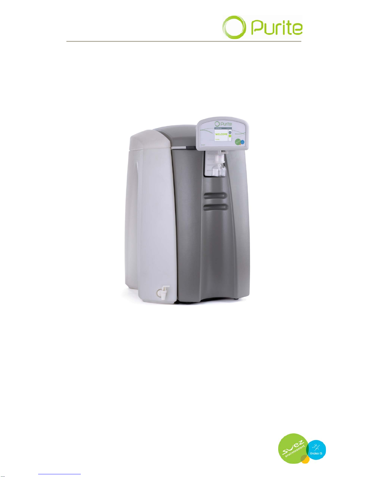
SELECT ANALYST
OPERATING MANUAL
ISSUE - A
1/9/09
Page 2

OPER
ATING MANUAL FOR SELECT ANALYST
Issue: A, part number R041118
2
Page 3

OPERATING MANUAL FOR SELECT ANALYST
Issue: A, part number R041118
3
CONTENTS PAGE
1 DOCUMENT HISTORY 5
2 CONTACT DETAILS 5
3 HEALTH AND SAFETY 7
3.1 Explanation of symbols and references. 7
3.2 Additional safety requirements. 7
3.3 Usage in accordance with intended purpose. 7
3.4 Operating staff. 7
3.5 Bringing the system to a stop in the event of an emergency. 8
3.6 Safety information for maintenance tasks. 8
3.7 Disposing of system parts and operating materials. 8
3.8 Unauthorised conversion & replacement parts. 8
3.9 Warranty claims and liability. 9
4 ABOUT YOUR WATER PURIFIER 11
4.1 The Select Analyst range of units. 11
4.2 Key components of the Select Analyst. 11
5 OPERATING YOUR WATER PURIFIER 13
5.1 Menu structure 13
5.2 Settings menu 14
5.3 Maintenance menu 18
5.4 Engineer menu 19
5.5 Auto restart 20
6 MAINTENANCE, SERVICE & SPARES 21
6.1 Replacing media packs 21
6.2 Cleaning inlet filter 21
6.3 Sanitisation procedure 22
6.4 Service spares 23
7 TROUBLE SHOOTING 25
8 TECHNICAL SPECIFICATION 27
8.1 Product outputs 27
8.2 Treated water specification 27
8.3 Water storage 27
8.4 Fuse rating/ type 27
Page 4

OPER
ATING MANUAL FOR SELECT ANALYST
Issue: A, part number R041118
9 INSTALLATION DETAILS
9.1 Media cartridge packs 29
9.2 Feedwater supply requirements 29
9.3 Electrical Supply 30
9.4 Unit positioning 30
9.5 Drain connection 32
9.6 Installation of media cartridge packs 32
10 APPENDIX 35
10.1 CE Declaration 35
10.2 WEEE Declaration 36
10.3 Process Flow Diagram 37
Page 5
OPER
ATING MANUAL FOR SELECT ANALYST
Issue: A, part number R041118
5
1 DOCUMENT HISTORY
Issue Date of
Change
Description of Change Approved by
A First Issue: 1/09/2009
2 CONTACT DETAILS
We trust the system will meet all your expectations. However, should you
have any additional questions concerning the equipment please do not
hesitate to contact Purite Ltd at:
Purite Ltd
Bandet Way
Thame e
Oxfordshire Oxfordshire
OX9 3SJ OX9 3SJ
United Kingdom United Kingdom
For all spares and consumable enquiries contact: For all spares and consumable enquiries contact:
Customer Services Department: Tel No. +44(0)1844 217141 Customer Services Department: Tel No. +44(0)1844 217141
For all service enquiries contact: For all service enquiries contact:
Service Department: Tel No. +44(0)1844 211555 Service Department: Tel No. +44(0)1844 211555
For further sales enquires contact: For further sales enquires contact:
Sales Department: Tel No. +44(0)1844 217141 Sales Department: Tel No. +44(0)1844 217141
Page 6

OPER
ATING MANUAL FOR SELECT ANALYST
Issue: A, part number R041118
6
Page 7
OPER
ATING MANUAL FOR SELECT ANALYST
Issue: A, part number R041118
7
3 HEALTH AND SAFTEY
3.1 Explanation of symbols and references
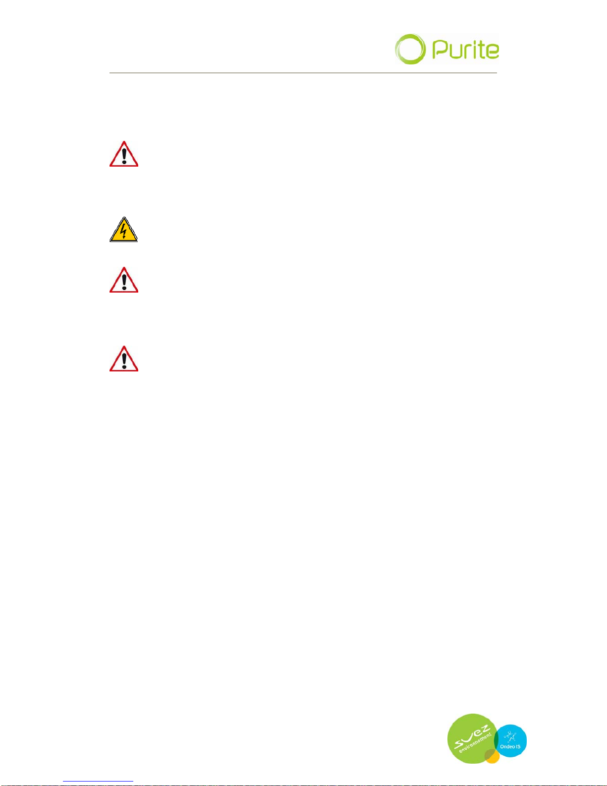
This symbol refers to any immediate dangers. Failure to
follow the specified procedure could result in serious
personal Injury. Extreme caution should be observed when
conducting any activity where this symbol is shown. Work
should be completed by a trained competent person.
Electrical shock. Do not touch electrical components. Before
performing tasks on parts of the electrical system, disconnect the
system from the power supply.
This symbol refers to a possible danger. Failure to follow the
specified procedure could result in personnel injury. Caution
should be observed when conducting any activity where this
symbol is shown. It is recommended work should be completed
by a trained competent person.
This symbol refers to a possibly hazardous situation.
Failure to observe these references may result in minor injuries
and/or damage to property.
Danger
Warning
Caution
I This symbol points out important information for working with the
system in the proper manner. Failure to observe these references
may result in malfunctions in the system or impact on the
environment.
3.2 Additional safety requirements
Country-specific requirements standards and regulations must be
observed.
3.3 Usage in accordance with intended purpose.
The units must only be operated with water supplied in accordance with
the quality described and the operating parameters specified in
“installation details”.
The units must not be operated unless in proper working order. Any
malfunctions must be rectified immediately.
3.4 Operating staff
Only persons who have read and understood this Operating Manual
should be permitted to operate the unit. When operating the units, it is
important to observe all safety information.
Page 8

OPER
ATING MANUAL FOR SELECT ANALYST
Issue: A, part number R041118
8
3.5 Bringing the system to a stop in the event of an
emergency
Switch off via the display.
Turn off the electrical supply.
Shut off the water supply.
After remedying the damage:
Open the water supply.
Turn on the electrical supply.
Restart the unit via the main display.
3.6 Safety information for maintenance tasks
The operator must take care to ensure that all maintenance, inspection
and assembly tasks are performed by authorised and qualified
professionals who have been sufficiently informed regarding the task at
hand (via use of Operating Manual).
The system must be shut down and be protected from further use until all
repair and maintenance tasks have been completed. It is essential to
observe the shutdown procedure as described in this Operating Manual.
Before beginning tasks relating to electrical equipment/components of this
system, a check must confirm that power has been disconnected from the
corresponding section of the system. In addition, the system must be
secured to prevent it from being turned on again unintentionally.
3.7 Disposing of system parts and operating materials
When they need to be discarded, consumables must be disposed of
according to local and National requirements.
3.8 Unauthorised conversion and manufacturing
replacement parts
Conversion or modification of the system is only permitted with the
approval of the manufacturer. The same applies to making changes in the
programming for the control system. Original replacement parts and
accessories authorised by the manufacturer enhance safety. Use of other
parts will void the warranty.
Page 9

OPER
ATING MANUAL FOR SELECT ANALYST
Issue: A, part number R041118
9
3.9 Warranty claims and liability
This product has been manufactured in accordance with ISO 9001:2008
procedures, after which it was subjected to a quality control process. If,
however, you are unsatisfied with the unit, please contact the
manufacturer (Purite Limited).
Page 10

OPER
ATING MANUAL FOR SELECT ANALYST
Issue: A, part number R041118
10
Page 11

OPER
ATING MANUAL FOR SELECT ANALYST
Issue: A, part number R041118
11
4 About your water purifier
The Purite Select Analyst purifies potable water. The water is purified by a
combination of processes including; ion-exchange, activated carbon and
reverse osmosis.
The purified water produced by the unit complies with latest standards for
laboratory grade purified water.
4.1 The Select Analyst range of units
GP: Generation unit (with no close coupled tank).
IT: Generation unit with close coupled 20 litre water storage
tank
GP BP: Generation unit with feed water boost pump
BP/IT: Generation unit with close coupled water storage tank and
feed water boost pump
Each of the above variants is available with 4 different output flow rates:
SA 40 6 litres per hour
SA 80 12 litres per hour
SA160 24 litres per hour
SA 320 48 litres per hour
Please note that the above outputs are based on an 8 hour working day at
60psi (4 bar) inlet pressure, 25oC and maximum of 400 ppm total dissolved
solids.
The unit type is detailed on its serial plate which can be found on the
reverse side of the front cover.
The Select Analyst is provided with an installation kit for quick installation.
Both media packs are provided and packaged separately. Refer to Section
9.1 and 9.6.
4.2 Key components of the Select Analyst
4.2.1 Touch screen display
Operation of the Select Analyst is controlled solely through the touch
screen display. System schematics are displayed for easy
understanding of the unit’s process.
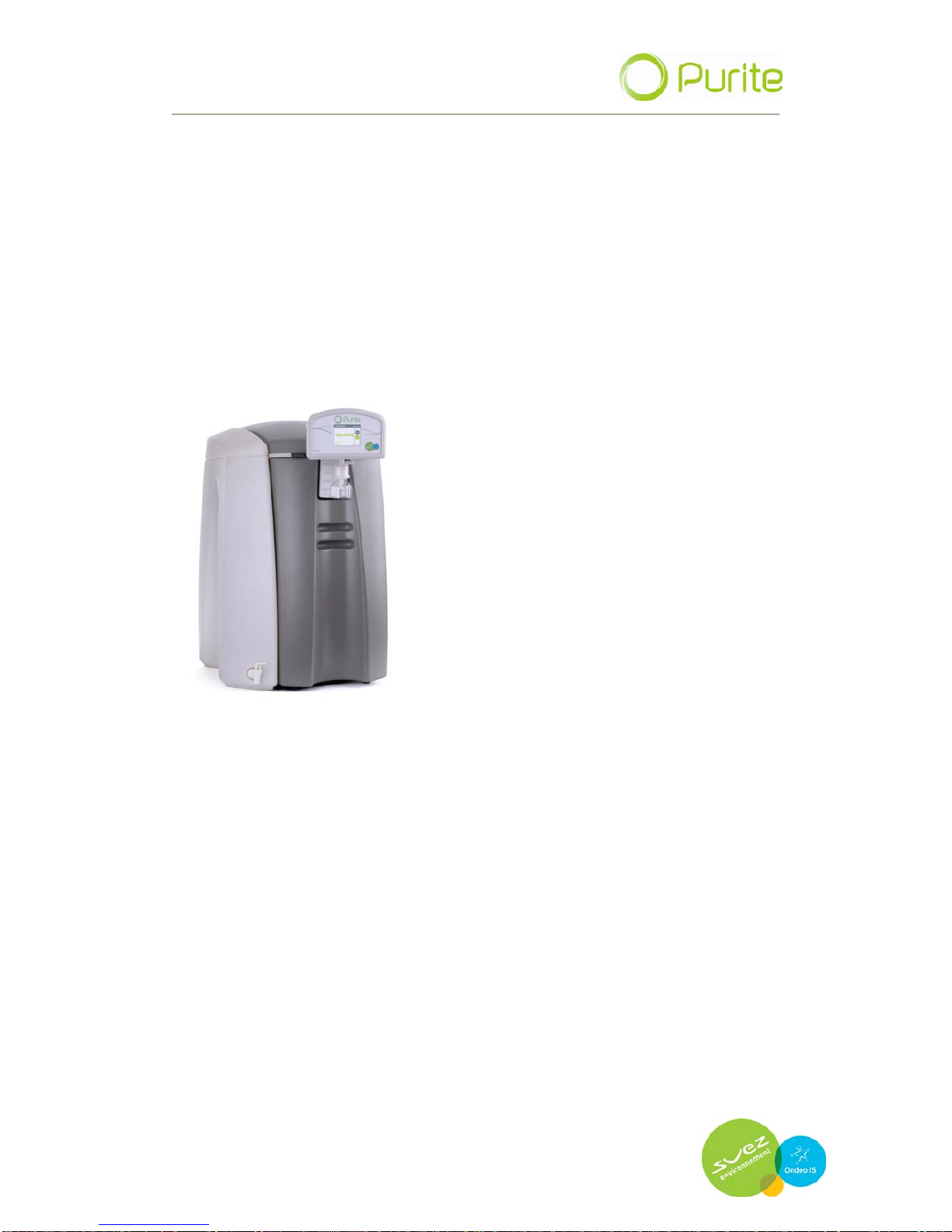
4.2.2 Close coupled tank
The close coupled tank holds 20 litres of purified water. To dispense
Page 12
OPER
ATING MANUAL FOR SELECT ANALYST
Issue: A, part number R041118
12
water a bib tap has been provided at the front of the tank.
Note: Generation units are NOT supplied with a water storage tank
4.2.3 Removable front cover.
The front cover is easily removed and provides access to the cartridge
media packs.
Page 13
OPER
ATING MANUAL FOR SELECT ANALYST
Issue: A, part number R041118
13
5 Operating your water purifier.
Your select Analyst is operated via the touch screen display. Buttons are
provided on the display to access both the start-up and set-up menus.
5.1 Menu structure (accessed via touch screen display).
5.1.1 Power on screen
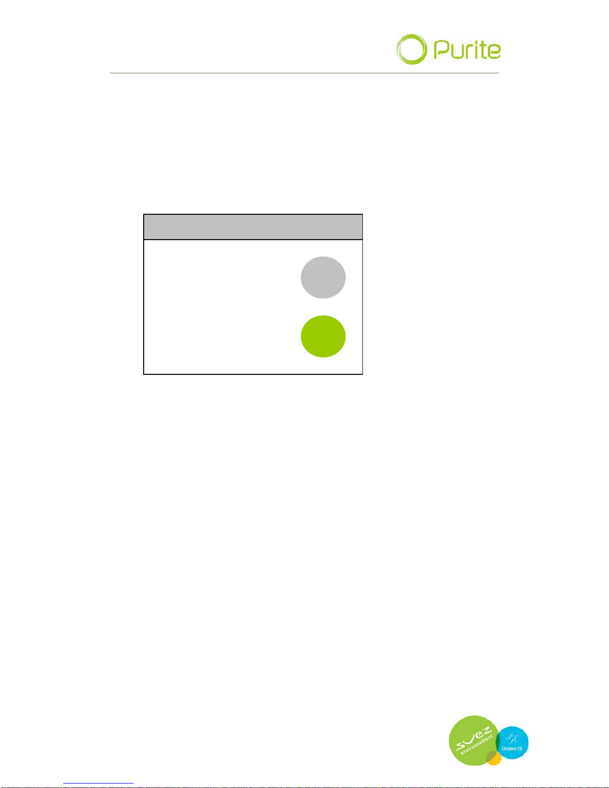
INITIALISING 09/09/09 10.22
MENU
WELCOME
ANALYST
START
When connected to an electrical supply the Power On screen is
displayed.
5.1.2 Start up screen
Start
Stop
Menu
→ Language
→ Time and date
→ Set time → Set time
→ Set date → Set date
→ set format → set format
→ Maintenance → Maintenance
→ Pre-treatment cartridge pack date → Pre-treatment cartridge pack date
→ Puripac cartridge pack date → Puripac cartridge pack date
→ Product Information → Product Information
→ Engineer Menu → Engineer Menu
→ Auto restart → Auto restart
→ Enable → Enable
→ Disable → Disable
Page 14
OPER
ATING MANUAL FOR SELECT ANALYST
Issue: A, part number R041118
14
The unit runs an initialisation for 10 seconds before the unit can be
activated. To switch the unit on press the START button after the
initialisation is compete
When start is pressed the following screen is displayed to show the unit
is in operation and processing water.
5.1.3 Processing screen
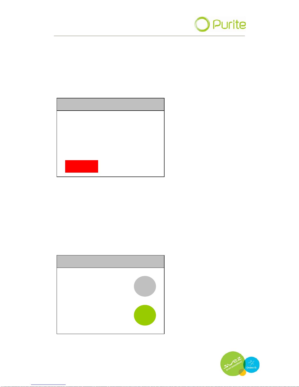
PROCESSING 09/09/09 10.22
QUALITY 10.0 MΩ
TEMPERATURE 20.0 °C
STOP
Outlet water quality and outlet water temperature are displayed on the
screen for your information.
A single red button is featured, STOP. When pressed the display reverts to
the Power On Screen and all functions are terminated.
5.2 Settings Menu
Pressing the MENU button takes you to the Settings Menu where system
parameters can be set up.
PROCESSING 09/09/09 10.22
MENU
WELCOME
ANALYST
ST
ART
All menu screens feature four buttons BACK, UP, DOWN, ENTER. nu screens feature four buttons BACK, UP, DOWN, ENTER.
Page 15
OPER
ATING MANUAL FOR SELECT ANALYST
Issue: A, part number R041118
15
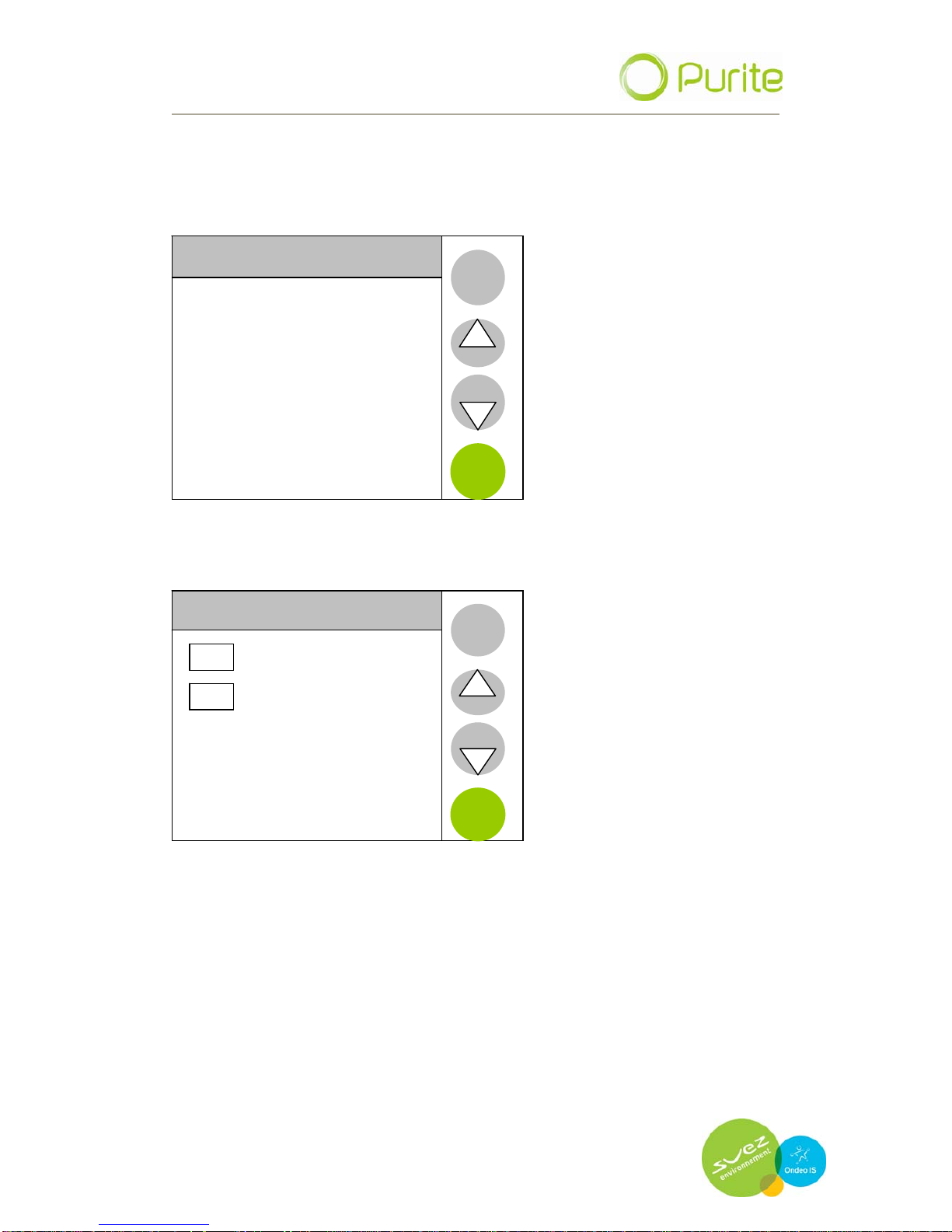
UP and DOWN are used to move through the available options and/or to
increase/decrease numerical vales.
ENTER selects to the option highlighted.
BACK returns to the previous screen.
SETTINGS MENU
Language
Time and Date
Maintenance
Product information
Engineer menu
BACK
Auto Restart
ENTER
5.2.1 Language
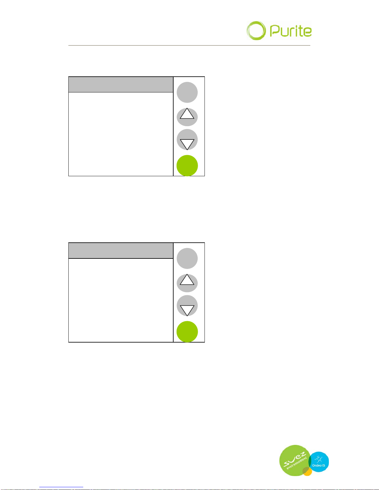
LANGUAGE
ENGLISH
FRENCH
BACK
ENTER
Text displays can be set to be shown in either English or French.
Highlight the appropriate tick box by pressing on the relevant screen area
and press enter.
Page 16
OPER
ATING MANUAL FOR SELECT ANALYST
Issue: A, part number R041118
16
5.2.2 Time and date
TIME AND DATE MENU
Set Time
BACK
Set Date
Set Format
ENTER
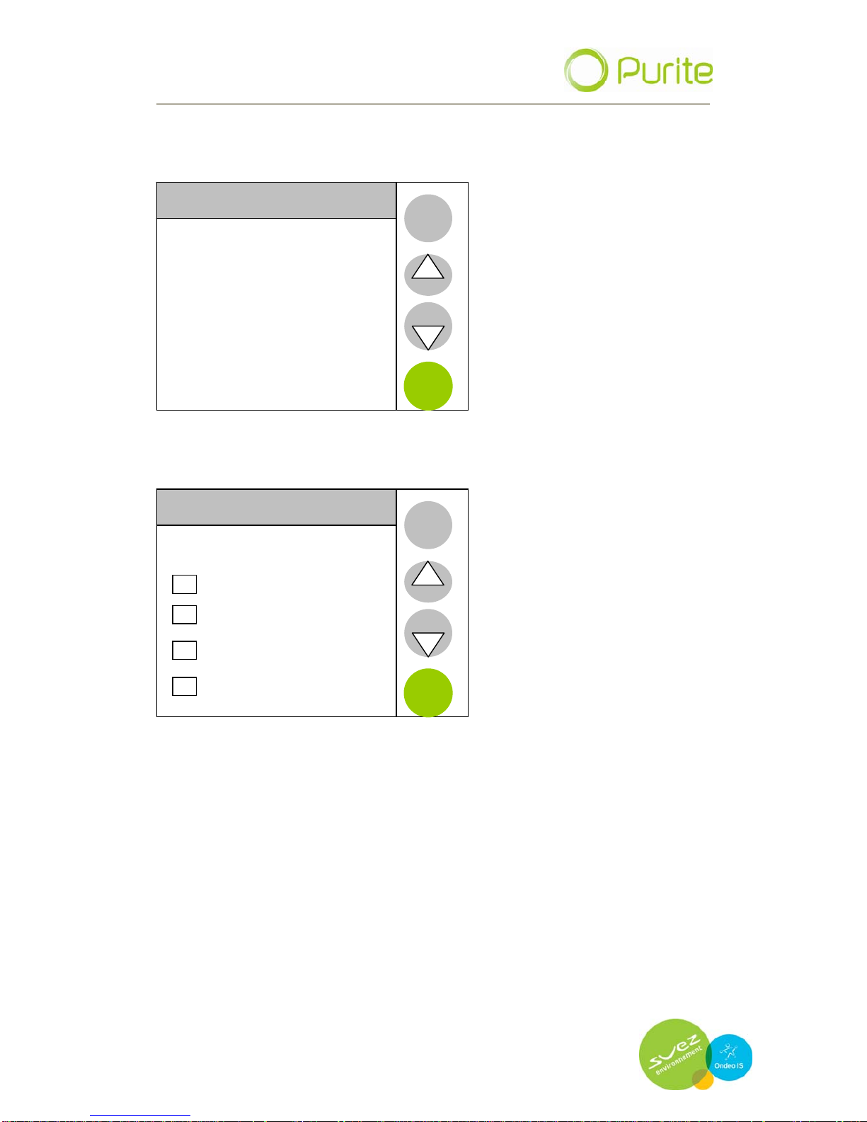
The system time and date can be set.
Set time.
The required time is programmed by using the up and down arrows to
select correct values, press enter to confirm.
PROCESSING
BACK
12:54
HH:MM
NEXT
Page 17
OPER
ATING MANUAL FOR SELECT ANALYST
Issue: A, part number R041118
17
Set date
SET DATE
04/01/09
DD/MM/YY
BACK
NEXT
Set date format
SET DATE
DD MM YY
DD MM YYYY
BACK
MM DD YY
MM DD YYY
ENTER
Page 18
OPER
ATING MANUAL FOR SELECT ANALYST
Issue: A, part number R041118
18
5.3 Maintenance menu
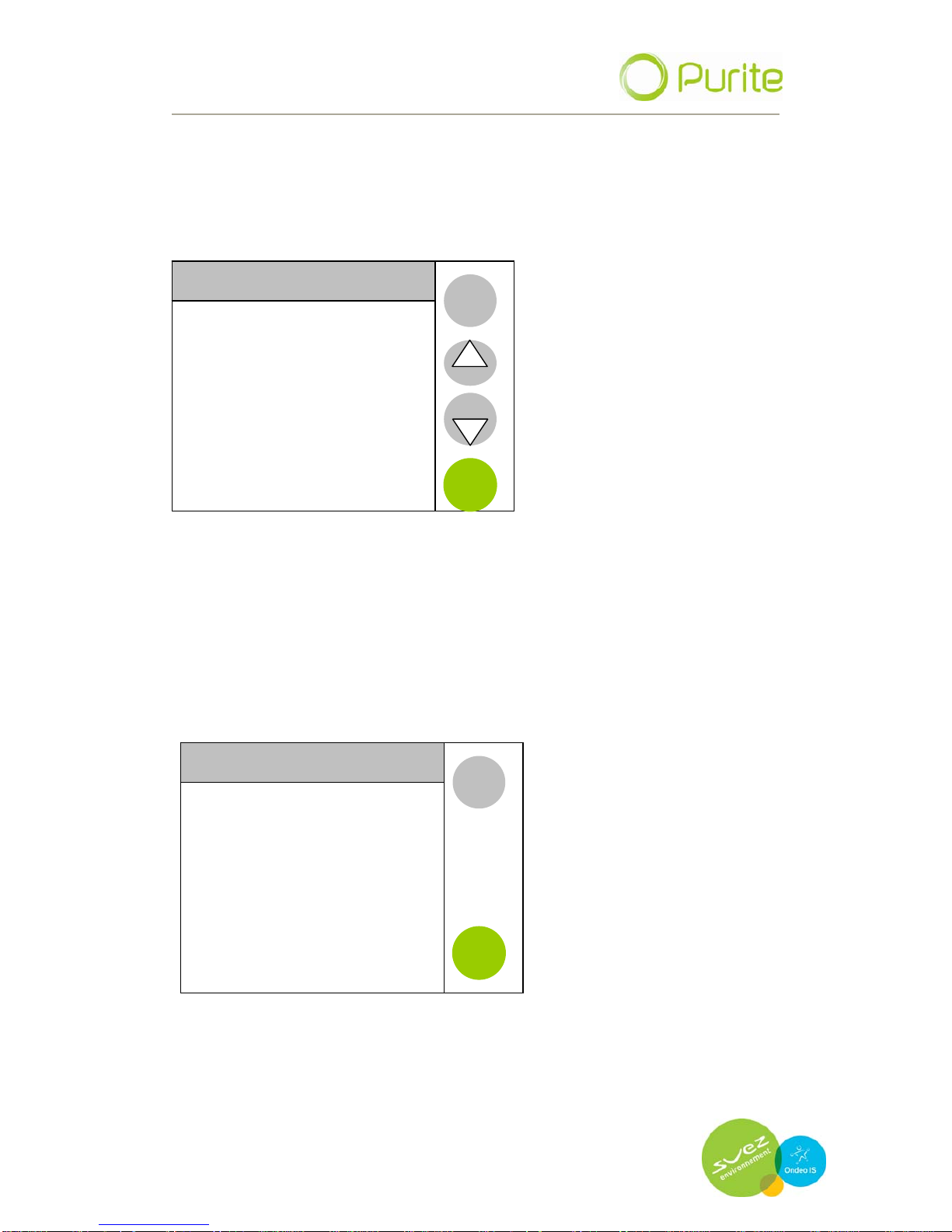
The maintenance menu provides the capability to set defined dates for
replacement of media cartridge packs in the device. These dates, when
expired, will trigger an alarm which will be displayed on the menu bar.
MAINTENANACE
Pretreatment Pack Date
BACK
Puripac Pack PP 8 Date
ENTER
5.3.1 Pretreatment pack date
When the Pretreatment (PT8) media packs are replaced it is necessary
to reset the replacement date. This is done via the Pretreatment Pack
date menu.
Enter the menu and press reset. Failure to reset and replace media
packs will lead to poor water quality.
Pretreatment Pack date
BACK
16/12/2009
6 MONTH EXPIRY
RESET
Page 19
OPERATING MANUAL FOR SELECT ANALYST
Issue: A, part number R041118
19
5.3.2 Puripac pack date
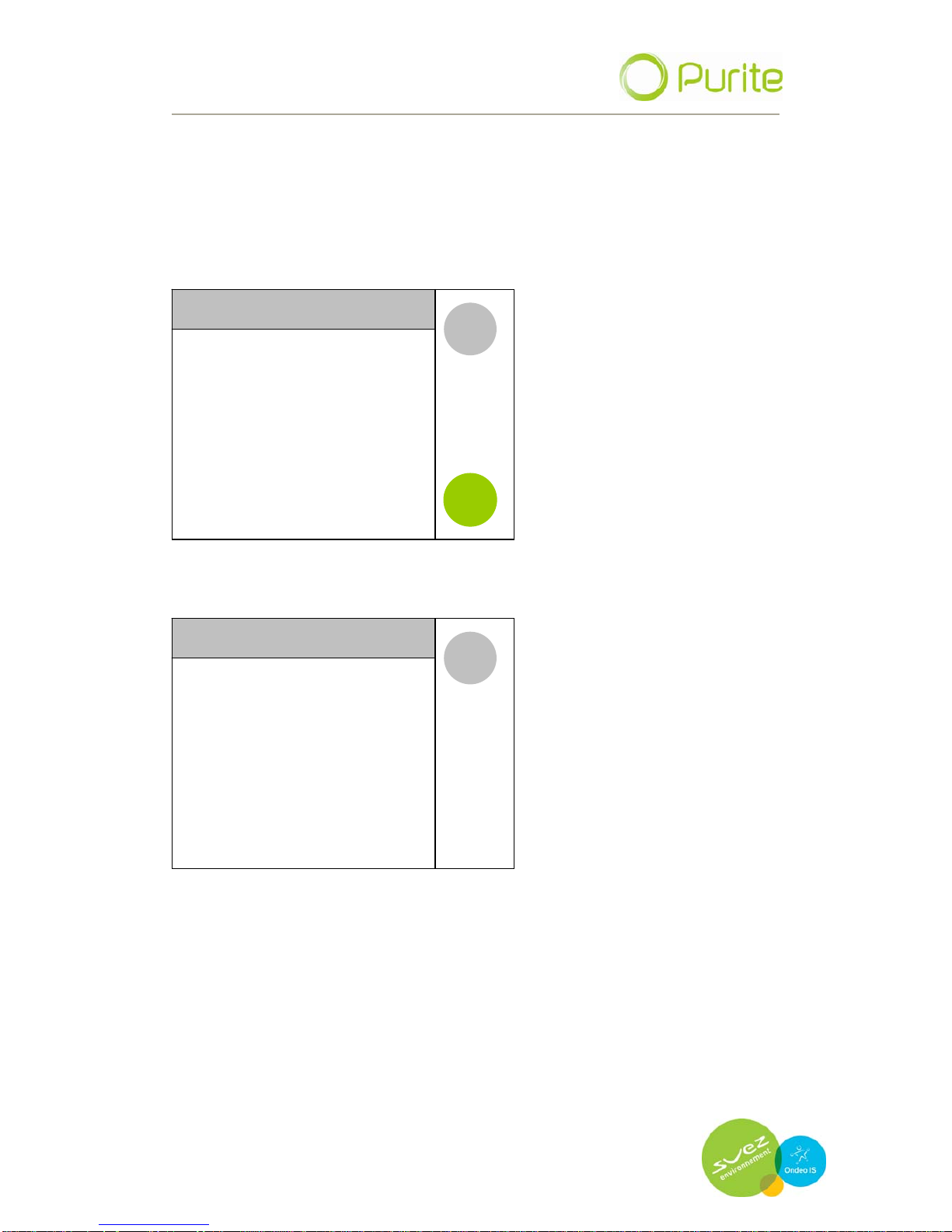
When the PP8/16 cartridge pack is replaced it is necessary to reset the
next replacement date. This is done in the Puripac date menu. Enter
the menu and press reset. Failure to reset and replace media packs will
lead to poor quality water.
Puripac date
BACK
16/12/2009
6 MONTH EXPIRY
RESET
5.3.3 Product information
Product Information
Type: Analyst
Serial number: 123456
Unit ID: 00
Unit Version: R.1.5
Pod Version : R.1.6
Commissioning Date: 01/01/01
BACK
Memory Chec
ksum: OxFE66
Address 02
5.4 Engineer menu
For Purite service engineers only.
Page 20
OPER
ATING MANUAL FOR SELECT ANALYST
Issue: A, part number R041118
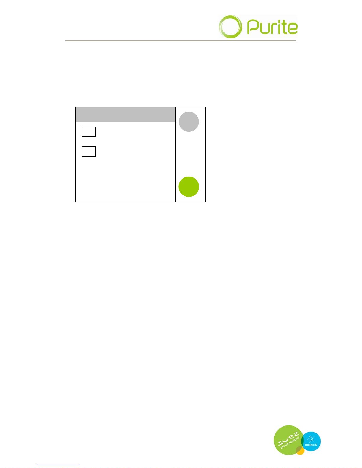
5.5 Auto restart
If selected will return the unit into operation automatically in the event of a
power cut.
AUTO RESTART
Disabled
Enabled
BACK
ENTER
Page 21

OPER
ATING MANUAL FOR SELECT ANALYST
Issue: A, part number R041118
21
6 MAINTENANCE
6.1 Replacing media packs
Switch the unit off by pressing the STOP button.
Leave the unit to stand for 30 seconds to relieve any internal pressure.
Remove the front door cover by pulling it gently from the unit using the
hand holds provided to expose the two media cartridge packs.
Press down the lever over the corresponding cartridge to be removed and
pull it away from its retainer.
Discard the exhausted media pack. Remove the new pack from its bag
removing the two black plugs from the inlet/outlet ports.
Insert the media pack into the unit locating it securely into its retaining
block, push it home until it clicks into position and the retaining lever clicks
up.
Press “START” and follow the instructions on screen for setting new pack
replacement date (see previous section)
After resetting the pack date the unit can be started from the power on
screen.
6.2 Cleaning inlet screen filter.
It is recommended that this filter is cleaned at least once per year.
The inlet screen filter is located in the right hand side of the unit.
Switch of the water supply at source
To relieve any residual water pressure, momentarily switch the unit on
then off.
Remove the side panel of the unit.
o To do so first remove the front cover by pulling it gently from the
unit using the hand holds provided.
o Pull the pod assembly gently forward to disengage the top cover
retaining pin.
o Remove the top cover by lifting up the front and sliding gently
backwards.
o Remove the four retaining screws holding the side panel in place
and slide gently backwards.
Page 22

OPER
ATING MANUAL FOR SELECT ANALYST
Issue: A, part number R041118
22
o The filter is located in the exposed panel on the right hand side
of the unit.
To obtain access to the filter screen unscrew the black knurled top anti-
clockwise. The screen will then be exposed. Pull the screen away
from the housing and clean away any debris.
Once cleaned, replace the screen and black top. Replace the side
panel and cover using the reverse procedure and switch on the water
supply. Start the unit from the power on screen
6.3 Sanitisation procedure.
Sanitisation of the unit should be carried out at least once every 6 months.
Switch the unit off by pressing the STOP button.
The unit will now have reverted to the POWER ON screen.
Turn off the water supply to the unit.
Open the front door cover to reveal the media cartridge packs.
Remove both media cartridge packs.
To sanitise the unit insert a cleaning pack adaptor (Purite part number
L998549) into each of the media pack locations.
Turn on the water supply and start the unit.
Allow the unit to fill the tank. When the tank is full the unit will stop.
Allow the unit to stand with a full tank for two hours. Drain the tank
using the bib tap located on the front of the tank.
The unit will automatically restart and begin to fill the tank. When the
tank is full drain it and allow it to fill once more.
When full switch the unit off, drain the tank and fit new media packs.
Restart the unit and allow it to fill the tank. When filled, switch the unit
off and drain the tank again.
Once the tank is drained check for residual sanitising chemicals.
Only when you are happy that all chemicals have been flushed from
the system should the unit be used. Test kits are available, contact
Purite for details.
Page 23
OPER
ATING MANUAL FOR SELECT ANALYST
Issue: A, part number R041118
23
6.4 Maintenance and service spares
PART No. DESCRIPTION
M996001 Select 40 RO membrane pack
M996002 Select 80 RO membrane pack
M996003 Select 160 RO membrane pack
MEMBRANE PACK
M996004 Select 320 RO membrane pack
L991542 PT8 Pretreatment pack
PRETREAT CARTRIDGES
L991544 PT16 Pretreatment pack
L991543 PP8 Puripac cartridge
PURIPAC CARTRIDGES
L991545 PP16 Puripac cartridge
L300900 Select wall mount kit
PM00901 Installation kit
INSTALLATION & WALL MOUNTS
L991110 Feed water pressure regulator
L991276 10" Filter housing
EXTERNAL FILTRATION
R011044 10µm Filter element
L998549 Cleaning pack adaptor
OTHERS
R041118 Operator's Manual (extra copies)
Page 24

OPER
ATING MANUAL FOR SELECT ANALYST
Issue: A, part number R041118
24
Page 25
OPER
ATING MANUAL FOR SELECT ANALYST
Issue: A, part number R041118
25
7 TROUBLE SHOOTING
The touch screen will display various alarms and/or error messages if a fault
is identified with the unit. The guide below can be used to rectify common
alarms.
Displayed Message Corrective action
LHS pack not fitted
Check left hand side media
pack is correctly located.
Push into position and listen
for a click to ensure it is fully
located in it retaining block
RHS pack not fitted
Check right hand side media
pack is correctly located.
Push into position and listen
for a click to ensure it is fully
located in it retaining block
High pressure (BP) variants
only
Feed water inlet pressure too
high.
Blockage in system
Check feed water supply
regulation
Call service department
Low pressure(BP) variants
only
Insufficient feed water
pressure
Check feed water supply
Check inlet screen
Change Puripac
Puripac cartridge exceeded
set date alarm or water
quality above set limits
Replace media packs and
reset system dates
Line cell error Faulty cable – open circuit Call service department
Page 26

OPER
ATING MANUAL FOR SELECT ANALYST
Issue: A, part number R041118
26
Page 27

OPER
ATING MANUAL FOR SELECT ANALYST
Issue: A, part number R041118
27
8 TECHNICAL SPECIFICATION
8.1 Product outputs
Unit Size
Product Outputs
40 80 160 320
@ 10 °C 3.6 7.2 14.4 30
@ 25 °C 6 12 24 48
8.2 Treated water specification
Inorganics 1-10MΩ.cm
pH1 Neutral
Bacteria >99% rejection
Organics (TOC) <50 ppb
1
pH of stored water may decrease due to absorption of free carbon
8.3 Water storage
Pure water storage Optional 20 litre tank (external 50 and 100 litre
tanks available)
8.4 Fuse rating / type
IEC module fuse type: - (20x5mm), T5AH250V, conforming to IEC 127
Number per unit = 2.
Page 28

OPER
ATING MANUAL FOR SELECT ANALYST
Issue: A, part number R041118
28
Page 29
OPER
ATING MANUAL FOR SELECT ANALYST
Issue: A, part number R041118
29
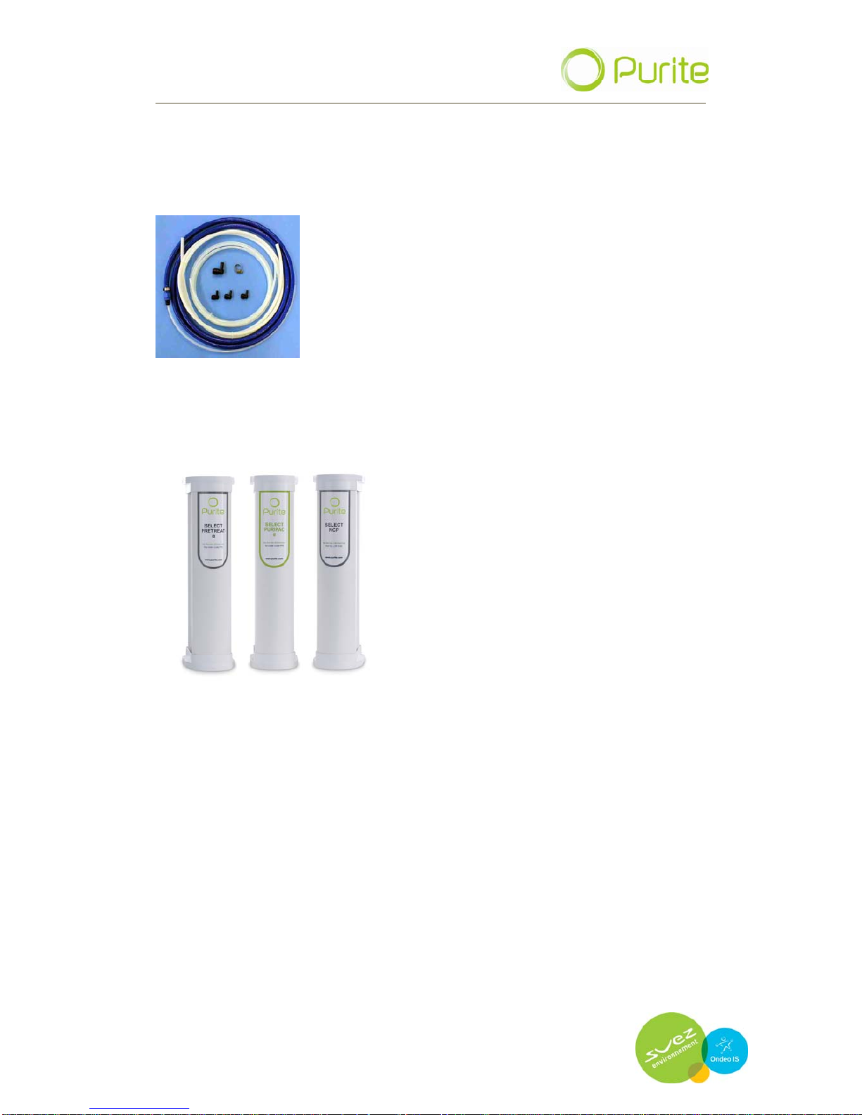
9 INSTALLATION KIT
Your installation kit comprises the following items.
Contents:
3 metres ½” Blue hose,
7metres 8mm nylon tubing,.
1 off Jubilee clip.
3 metres ,12mm nylon tubing,.
1 off 12mm stem elbow.
3 off 8mm stem elbows.
9.1 Media cartridge packs
Your Select Analyst is supplied with two different media cartridge packs
which are available in two sizes depending on your unit capacity.
A media preteatment pack and a Puripac polishing cartridge. Size 8 for
unit types 40,80,160 and size 16 for unit type 320.
The Select Analyst must be fitted with a media pre-treatment pack
PT8/PT16 and a Puripac PP8 /PP16.
The pretreatment pack must be fitted in the left hand position and the
Puripac cartridge in the right hand position when viewed from the front.
Refer to Section 6.4, Maintenance and service spares, for re-ordering
details.
Page 30
OPER
ATING MANUAL FOR SELECT ANALYST
Issue: A, part number R041118
30
9.2 Feed water supply requirements
The unit has been designed to operate only on potable tap water and
should comply with the following limits.
Feed water supply requirements
Free Chlorine < 1 ppm as Cl2
Total dissolved solids (max) 1000 ppm
Temperature 1-35oC (33.8 – 95o F)
Feed water pressure (max) 90 psi
Feed water pressure (min) 30 psi*
Optimum pressure 60 psi
* If your feedwater pressure is below this minimum value the performance
of the unit will be affected
Contact your water supplier if outside these limits.
9.3 Electrical supply
Your Select Anaylst will require a single phase electrical supply that meets
the requirements below
Electrical
Supply
KW
Rating
Current
Draw (Amps)
External Fuse
Rating
Single phase
100-240v +
10%,
50 Hz and Earth
0.1
1.0
5 Amps
(conforming to
BS1362)
Ensure that the mains supply is provided via a convenient switched outlet
and is protected with a 5 amp fuse.
9.4 Unit positioning
The Select Analyst has been designed to be bench or wall mounted.
9.4.1 Bench mounted
Locate the unit on a suitable work surface, ensuring access to tank
dispense bib tap and sufficient clearance to rear of the machine for all
water and electrical connections.
All water feed connections are found on the rear of the unit. Using the
installation kit provided attach the water feed, drain and overflow tubing
as shown below.
Page 31
OPER
ATING MANUAL FOR SELECT ANALYST
Issue: A, part number R041118
31
9.4.2 Wall mounting
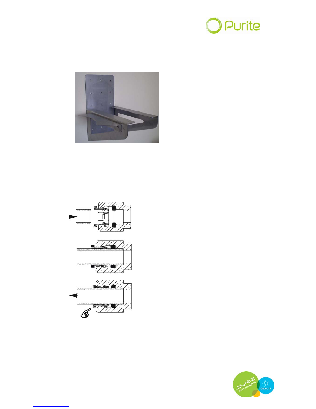
Use a wall mount bracket (Part Number L300900 shown below)
Secure the bracket to a suitable wall. Careful consideration should be
given to the strength and suitability of the wall as the working weight of
the select Analyst is 50Kg.
Secure the bracket to the wall. Remove the feet of the Analyst by
unscrewing them. Place the Analyst on the wall bracket and fix to the
bracket using screws through the feet mounting points.
All hoses are connected to the unit via its push
fit connectors. To make a connection, the hose
is simply pushed in by hand; the unique
patented locking system then holds the tube
firmly in place without deforming it or restricting
flow.
Cut the tube square and push in until the tube
stops.
Ensure the tube is pushed into the tube stop,
securing tube in position.
To remove tubing push collet against body and
slide tube out of fitting
Water Inlet connection:
Fit 8mm tubing to the water inlet connector found on the rear of the
unit and the other end to your water supply.
Page 32
OPER
ATING MANUAL FOR SELECT ANALYST
Issue: A, part number R041118
32
9.5 Drain connection
Attach a suitable length of 8mm tubing to the drain connection so that the
free end may be inserted into an appropriate drain. The tubing must not be
kinked or the flow restricted in anyway.
If the drain is to be run over 5 meters and/or rises above the level of the
unit then contact our Service Department for advice.
Attach a suitable length 12mm hose to the overflow connection on the unit
and run to a suitable drain point. If the drain is to be run over 5 meters
and/or rises above the level of the unit then contact our Services Dept for
advice.
9.6 Installation of media cartridge packs
Remove the door of the unit by tugging gently on the hand hold provided in
the door.
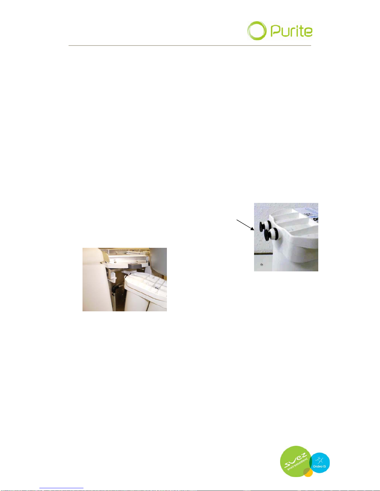
Remove the cartridge media packs from their
packaging and remove the black protective caps
from the inlet and outlet ports.
Insert the Pretreatment (PT8 or PT16) in the left hand retaining block
pushing it home until it clicks into position and retaining mechanism clicks
up.
Insert the Puripac PP8 or PP16 pack in the right hand retaining block
pushing it home until it clicks into position and retaining mechanism clicks
up.
Replace the door by locating the top of the door under the retaining
mouldings and lifting the bottom of the door until it slides home.
Switch on water supply to the unit.
Switch on the electrical supply to the unit.
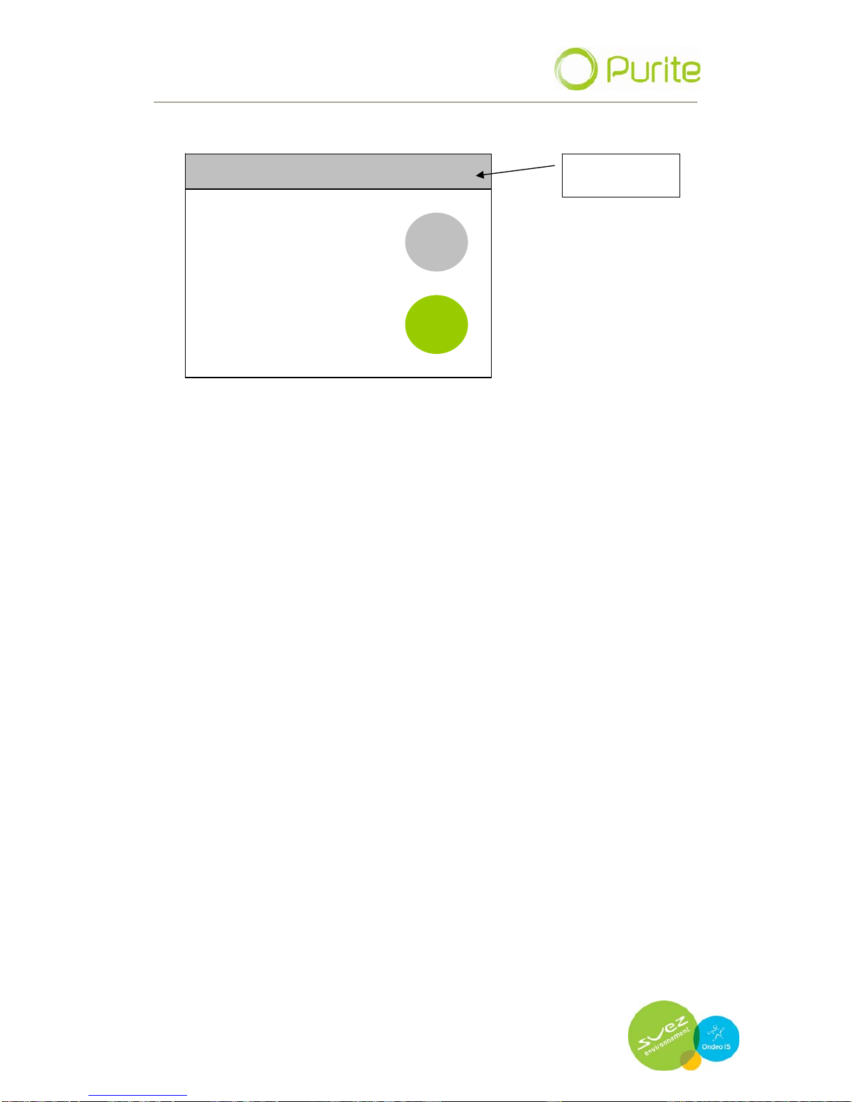
This touch screen display will illuminate and display the start screen.
Page 33
OPER
ATING MANUAL FOR SELECT ANALYST
Issue: A, part number R041118
33
Menu / text bar
PROCESSING 09/09/09 10.22
MENU
WELCOME
ANALYST
ST
ART
Page 34

OPER
ATING MANUAL FOR SELECT ANALYST
Issue: A, part number R041118
34
Page 35
OPER
ATING MANUAL FOR SELECT ANALYST
Issue: A, part number R041118
35
10 Appendix
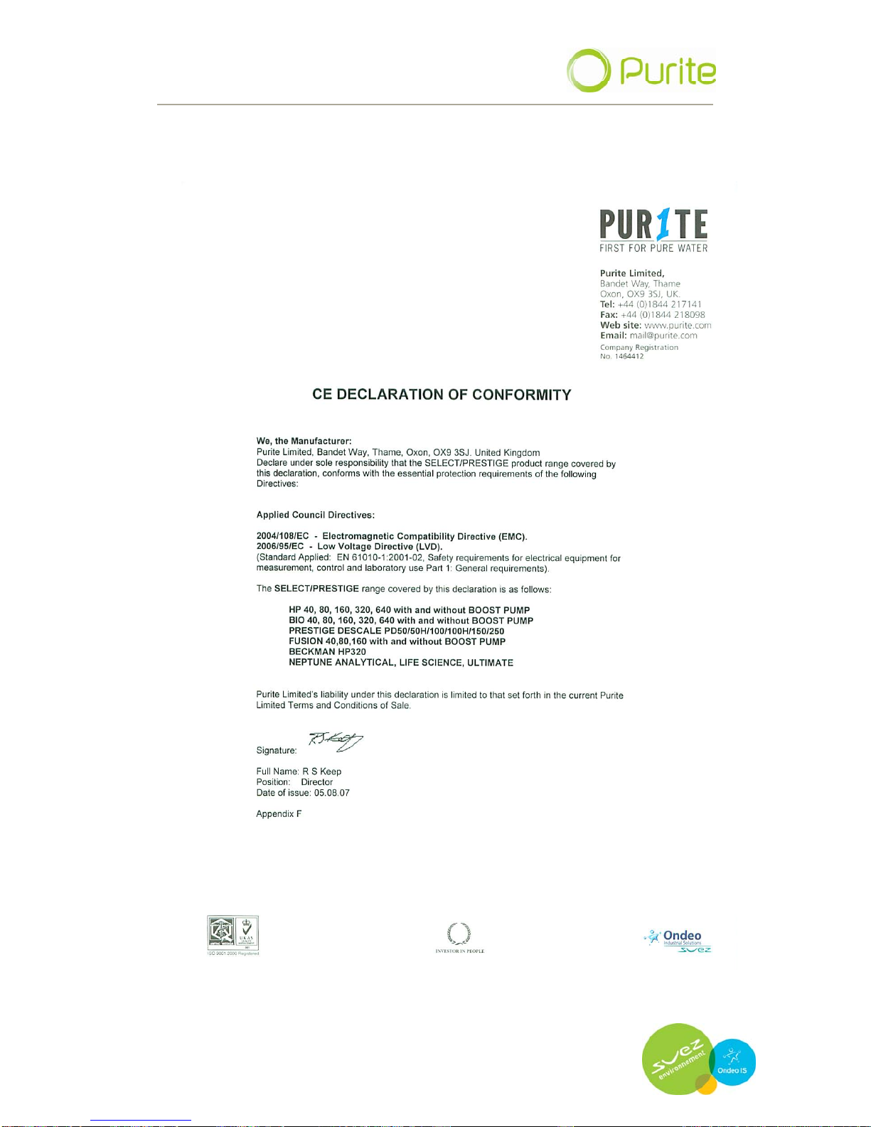
10.1 CE declaration
Page 36
OPER
ATING MANUAL FOR SELECT ANALYST
Issue: A, part number R041118
36
10.2 WEE declaration
Page 37

OPER
ATING MANUAL FOR SELECT ANALYST
Issue: A, part number R041118
37
10.3 Process flow
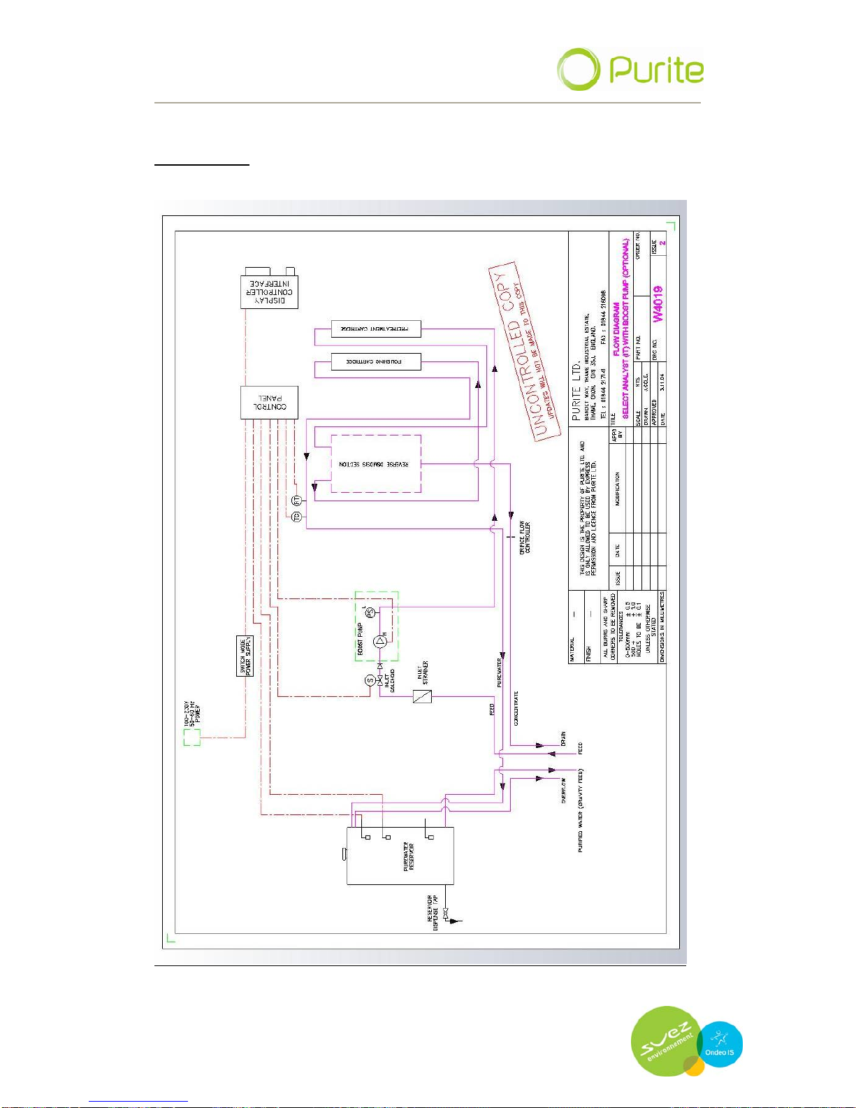
(to be read in conjunction with flow diagram)
All external hydraulic and electrical connections are positioned at the
rear of the unit, in order to protect them from accidental damage.
On entering the Select Analyst an internal feed water strainer removes
any large debris remaining in the feed water supply. When operated,
an inlet solenoid opens and allows water to pass to the reverse
osmosis boost pump (option).
The boost pump increases the feed water pressure to a level to enable
the reverse osmosis (RO) membranes to operate efficiently.
Prior to entering the RO modules the water is passed through a pre-
treatment pack to remove chlorine from the feed water to protect the
RO membranes.
The Pre-filtered, water enters the reverse osmosis module/s. Purified
water passes through the membrane and is termed; the permeate (8595% of salts removed). The water containing the rejected salts passes
across the membrane and out of the RO module to drain and is termed,
the concentrate.
The concentrate flow rate is controlled by a fixed orifice restrictor
located in the drain line.
The, permeate is further purified by a Puripac media cartridge
containing mixed ion-exchange resin and activated carbon. The
deionised water then feeds directly into the integral 20 litre storage
tank. Water can be dispensed from this tank via the front mounted bib
tap.
.
Page 38
OPERATING MANUAL FOR SELECT ANALYST
Issue: A, part number R041118
38
Flow diagram
 Loading...