

Page 1
User Manual
PT-HDBT-701-TXWP
User Manual
HDBaseT 1.0 Extender, 4K (60Hz 4:2:0) HDR
Model PT-HDBT-701-TXWP
Designed in Germany
© 2018 PureLink GmbH All rights reserved. V1.1
Page 2

User Manual
PT-HDBT-701-TXWP
Preface
Read this user manual carefully before using this product. Pictures shown in this
manual are for reference only. Different model layouts and specifications are subject
to the physical product.
This manual is for operation instructions only, not for any maintenance usage.
In the constant effort to improve our product, we reserve the right to make changes in
functions or parameters without prior notice or obligation.
Trademarks
Product model and logo are trademarks. Any other trademarks mentioned in this
manual are acknowledged as the properties of the trademark owner. No part of this
publication may be copied or reproduced without the prior written consent.
FCC Statement
This equipment generates, uses and can radiate radio frequency energy and, if not
installed and used in accordance with the instructions, may cause harmful
interference to radio communications. It has been tested and found to comply with
the limits for a Class B digital device, pursuant to part 15 of the FCC Rules. These
limits are designed to provide reasonable protection against harmful interference in
a commercial installation.
Operation of this equipment in a residential area is likely to cause interference, in
which case the user at their own expense will be required to take whatever measures
may be necessary to correct the interference.
Any changes or modifications not expressly approved by the manufacture would void
the user’s authority to operate the equipment.
Page 3

User Manual
PT-HDBT-701-TXWP
REACH | 1907/2006/EU
ROHS | 2011/65/EU
PureLink hereby declares that this product PureTools PT-HDBT-701-TXWP complies
with Directives 1907/2006/EU und 2011/65/EU.
EMC / LVD (Electro Magnetic Compatibility / Low Voltage Directive)
PureLink GmbH hereby declares that this product PureTools PT-HDBT-701-TXWP
complies with Directives 2014/30/EU and 2014/35/EU. The full text of the EU
Declaration of Conformity is available at the following Internet address:
http://www.purelink.de/ce/4251364706794_CE.pdf
Page 4

User Manual
PT-HDBT-701-TXWP
SAFETY PRECAUTIONS
To insure the best from the product, please read all instructions carefully before using
the device. Save this manual for further reference.
Unpack the equipment carefully and save the original box and packing material
for possible future shipment
Follow basic safety precautions to reduce the risk of fire, electrical shock and
injury to persons.
Do not dismantle the housing or modify the module. It may result in electrical
shock or burn.
Using supplies or parts not meeting the products’ specifications may cause
damage, deterioration or malfunction.
Refer all servicing to qualified service personnel.
To prevent fire or shock hazard, do not expose the unit to rain, moisture or install
this product near water.
Do not put any heavy items on the extension cable in case of extrusion.
Do not remove the housing of the device as opening or removing housing may
expose you to dangerous voltage or other hazards.
Install the device in a place with fine ventilation to avoid damage caused by
overheat.
Keep the module away from liquids.
Spillage into the housing may result in fire, electrical shock, or equipment
damage. If an object or liquid falls or spills on to the housing, unplug the module
immediately.
Do not twist or pull by force ends of the optical cable. It can cause malfunction.
Do not use liquid or aerosol cleaners to clean this unit. Always unplug the power
to the device before cleaning.
Unplug the power cord when left unused for a long period of time.
Information on disposal for scrapped devices: do not burn or mix with general
household waste, please treat them as normal electrical wastes.
Page 5

User Manual
PT-HDBT-701-TXWP
Contents
1. Introduction .................................................................................................................................. 1
1.1 Introduction to PT-HDBT-701-TXWP ........................................................................... 1
1.2 Feature ................................................................................................................................ 1
1.3 Package List ....................................................................................................................... 2
2. Panel Description ........................................................................................................................ 3
2.1 Front Panel ......................................................................................................................... 3
2.2 Rear Panel .......................................................................................................................... 4
2.3 Side Panel ........................................................................................................................... 5
3. System Connection ..................................................................................................................... 6
4. Button Control .............................................................................................................................. 8
5. RS232 Control .............................................................................................................................. 9
5.1 RS232 Connection............................................................................................................ 9
5.2 RS232 Control Software ...............................................................................................11
5.3 RS232 Command ............................................................................................................13
5.3.1 Control Mode Switching................................................................................... 13
5.3.2 Signal Switching ................................................................................................. 13
5.3.3 VGA Scaling Configuration .............................................................................. 13
5.3.4 HDCP Compliance .............................................................................................. 14
5.3.5 VGA Image Adjustment .................................................................................... 14
5.3.6 EDID Configuration ........................................................................................... 16
5.3.7 Device Configuration ........................................................................................ 17
6. Specification .............................................................................................................................. 18
7. Panel Drawing ........................................................................................................................... 19
8. Troubleshooting & Maintenance .......................................................................................... 20
9. After-Sales Service ................................................................................................................... 21
Page 6

User Manual
PT-HDBT-701-TXWP
1
1. Introduction
1.1 Introduction to PT-HDBT-701-TXWP
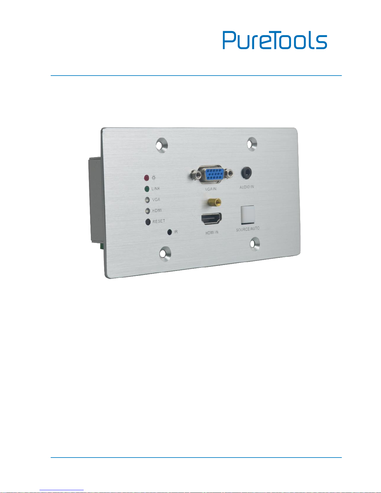
The PT-HDBT-701-TXWP is 2x1 wallplate HDBaseT Transmitter for switching and
extending HDMI or VGA + audio input to display or projector, and the transmission
distance is up to 40m@4K and 70m@1080p over a single Cat5e/6/7 cable based on
Certified HDBaseT technology. The resolution of HDMI input is up to 4K/UHD@ 60Hz
4:2:0 and VGA input up to 1920x1200.
The PT-HDBT-701-TXWP is ideal for huddle rooms, classrooms and small conference
rooms. The wall‑mountable design provides the convenience of placing input
connections precisely where they are needed.
1.2 Feature
Features one HDMI input and one VGA input with 3.5mm analogue audio input.
Supports HDMI signal up to 4K@60Hz 4:2:0, VGA input signal up to 1920 x
1200.
Built-in scaling function to match signals to display native resolution.
Ensures display of content-protected media and interoperability with other
HDCP compliant devices.
Audio signal can be selectively embedded into the video output.
HDBaseT technology extend HDMI and VGA, Audio, control signals up to 70m
over CATx cable.
Automatically detect active inputs when sources are connected.
Flexible control options for compatibility with third-party system, matrix
switcher or receiver.
Page 7

User Manual
PT-HDBT-701-TXWP
2
Supports bi-directional RS232 pass-through with HDBaseT connection and local
control.
PoH (power over HDBaseT) allows powering from the receiver at the display
end.
Provides power supply for devices like Control Panel.
1.3 Package List
1 x PT-HDBT-701-TXWP 4K Wallplate HDBaseT Transmitter
1 x 2-pin Pluggable Terminal Block
1 x 4-pin Pluggable Terminal Block
1 x User Manual
Note: Please confirm if the product and the accessories are all included, if not, please
contact with the dealers.
Page 8
User Manual
PT-HDBT-701-TXWP
3
2. Panel Description
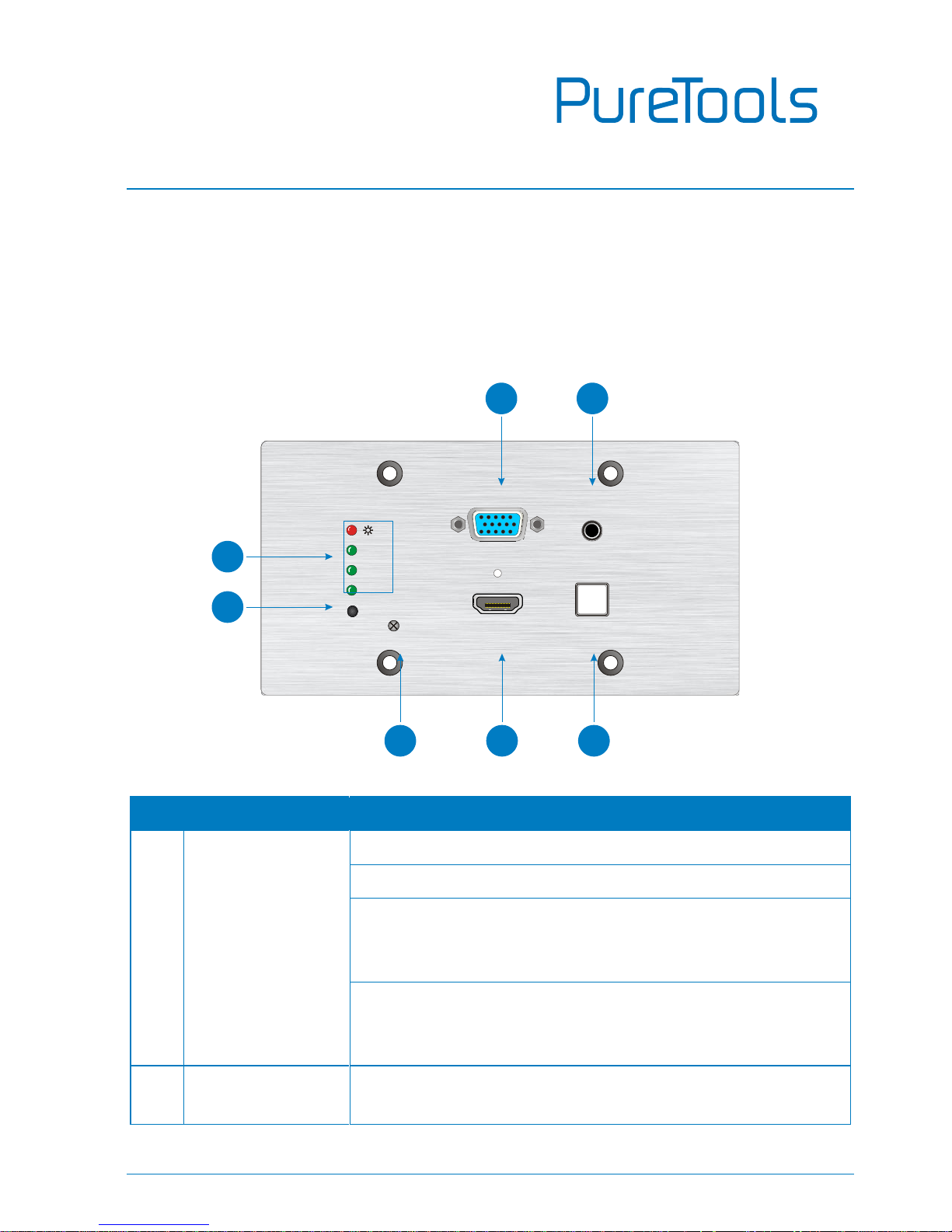
2.1 Front Panel
No.
Name
Description
①
LED indicator
POWER: Glows red when power is applied.
LINK: Glows green when an HDBaseT link is established.
VGA: Glows green when the VGA input is active, amber
when a source is available, and off when there is no
source connected.
HDMI: Glows when HDMI input is active, amber when a
source is available, and does not light when there is no
source connected.
②
RESET
This button performs a soft reboot of the PT-HDBT-701TXWP.
VGA IN AUDIO IN
HDMI IN
SOURCE/AUTO
LINK
VGA
HDMI
IR
RESET
3
6
5
7
4
1
2
Page 9
User Manual
PT-HDBT-701-TXWP
4
No.
Name
Description
③
VGA IN
VGA input connector, connect with VGA source.
④
AUDIO IN
3.5mm stereo audio connector supplies audio for the VGA
input.
⑤
IR
Built-in IR sensor to receive IR signal from IR remote.
⑥
HDMI IN
HDMI input connector, connect with HDMI source.
⑦
SOURCE/AUTO
Backlight Button.
Press this button to switch input signal manually
between HDMI and VGA sources.
Press and hold this button 3 seconds, the LED turn
green to enter auto-switching mode. Press and hold
again can exit this mode.
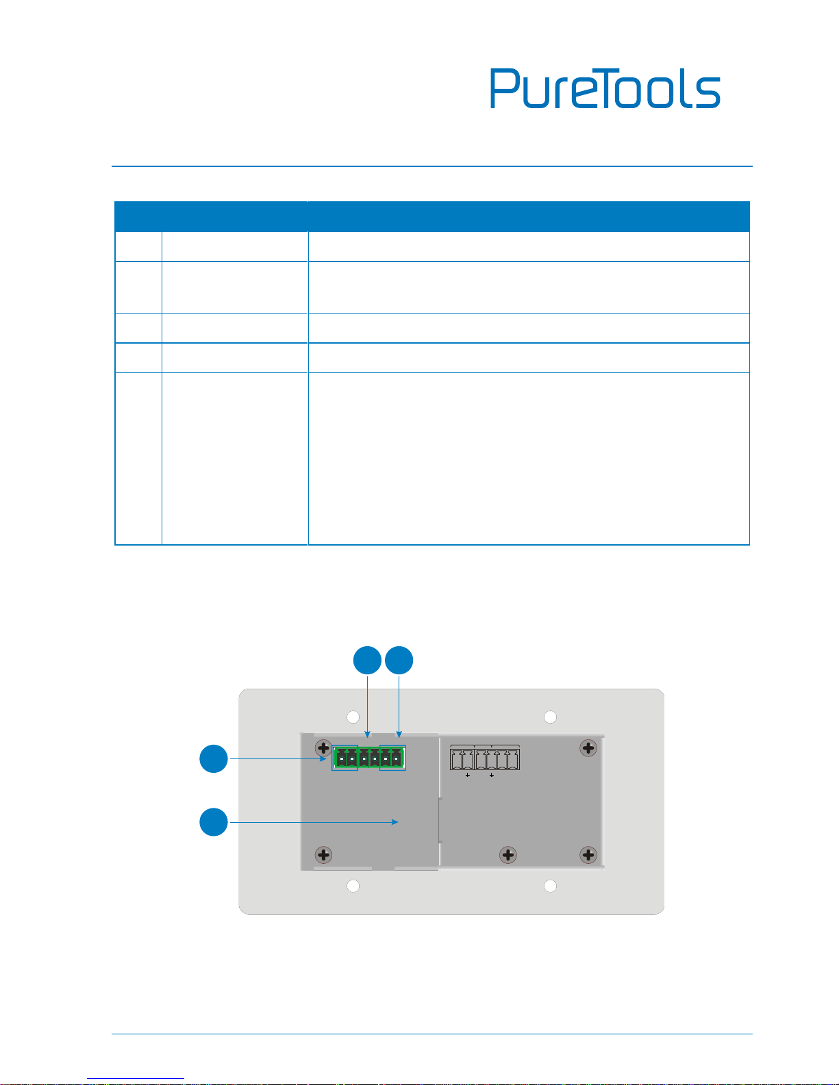
2.2 Rear Panel
Tx Rx 12V 12V
RS23 2
IN
OUT
PoH IN
HDBT OUT
3
4
1
2
Page 10
User Manual
PT-HDBT-701-TXWP
5
No.
Name
Description
①
HDBT OUT
(PoH IN)
HDBaseT output, connects with HDBaseT Receiver over a
single Category cable to deliver AV signals, support PoH.
②
IN
12V input, connects with power adapter.
③
OUT
12V output, connects with Control Panel to energize it.
④
RS232
Serial port for control PT-HDBT-701-TXWP or the third-party
device via RS232 commands. Please refer to the 5. RS232
Control for more details.
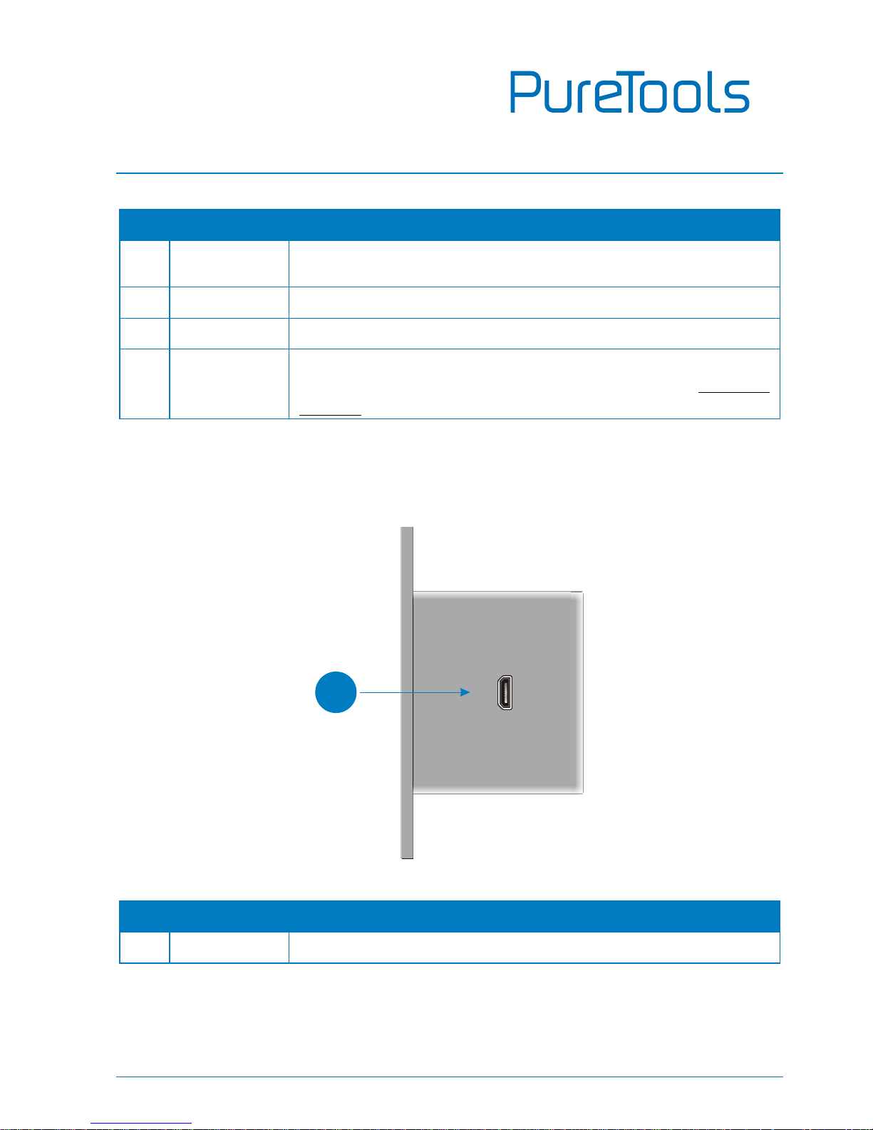
2.3 Side Panel
No.
Name
Description
①
FIRMWARE
Micro-USB connector used for firmware update.
FIRMWARE
1
Page 11
User Manual
PT-HDBT-701-TXWP
6
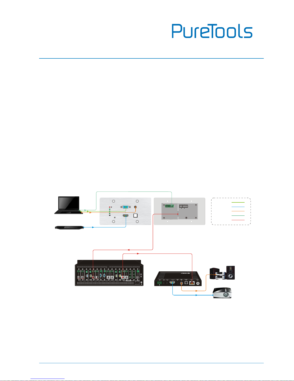
3. System Connection
Usage Precautions
Verify all components and accessories included before installation.
System should be installed in a clean environment, preferably at ambient
temperature or within given working temperature range (see page18 for limits).
All of the power switches, plugs, sockets and power cords should be insulated
and safe.
All devices should be connected before power on.
Overview:
VGA IN AUDIO IN
HDMI IN SOU RCE/AUTO
LINK
VGA
HDMI
IR IN
RESET
Tx Rx 12V 12 V
RS232IN OUT
PoH IN
HDBT OUT
OUTPUTS 13~16
AUDIO
MIC IN AUDIO OUT
RL
MIX OUT
RL
OUTPUT
4K
Tx Rx
RL
IR OUTIR IN
RS232 AUDIO
HDBaseT
OUTPUT
4K
Tx Rx
RL
IR OUTIR IN
RS232 AUDIO
HDBaseT
OUTPUT
4K
Tx Rx
RL
IR OUTIR IN
RS232 AUDIO
HDBaseT
OUTPUT
4K
Tx Rx
RL
IR OUTIR IN
RS232 AUDIO
HDBaseT
OUTPUT
HDMI
AUDIO
L R
4K
OUTPUT
HDMI
AUDIO
L R
4K
OUTPUT
HDMI
AUDIO
L R
4K
OUTPUT
HDMI
AUDIO
L R
4K
4K
RS232 AUDIO
Tx Rx
RL
INPUT
IR OUTIR IN
HDBaseT
4K
RS232 AUDIO
Tx Rx
RL
INPUT
IR OUTIR IN
HDBaseT
4K
RS232 AUDIO
Tx Rx
RL
INPUT
IR OUTIR IN
HDBaseT
4K
RS232 AUDIO
Tx Rx
RL
INPUT
IR OUTIR IN
HDBaseT
AUDIO
MIC IN AUDIO OUT
RL
MIX OUT
RL
Tx Rx
Receiver
Projector
Speaker
Matrix
PT-HDBT-701-TXWP
Laptop
Blu-ray
1080P 70m
4K 40m
HDMI:
HDBaseT:
RS232:
Audio:
VGA:
Page 12

User Manual
PT-HDBT-701-TXWP
7
Installation
① If installing in a back-box, it is recommended that the PT-HDBT-701-TXWP be
installed in a suitable square box. The square box has sufficient space to
terminate the cables with jacks behind the unit when fully installed.
② Run one Cat5e/6/7 cable from the PT-HDBT-701-TXWP location to the location
where the HDBaseT Receiver/ Matrix Switcher will be located (somewhere near
the display device).See the installation instructions for the 70M HDBaseT
Receiver.
③ If using the Control Panel, run another twisted pair cable from the PT-HDBT-701-
TXWP location to the location that the Control Panel will be mounted.
④ All Cat5e/6/7 cables should be terminated with jacks. This allows the permanent
link between the two devices to be tested.
⑤ Use the appropriate category rated patch cable to connect the HDBaseT link to
the HDBT OUT connector.
⑥ If using the Control Panel, use the supplied adapter cable to connect with the
second cable and follow the installation instructions for the HDBaseT Receiver
and Control Panel.
Note: We recommends Cat5e/6/7 cabling with alien crosstalk prevention technology for
the performance of HDBaseT link.
Page 13

User Manual
PT-HDBT-701-TXWP
8
4. Button Control
SOURCE/AUTO Button
Press and hold the SOURCE/AUTO button for 3 seconds. When the button lights up
green the PT-HDBT-701-TXWP is in AUTO mode. This mode automatically selects the
last video source connected to the PT-HDBT-701-TXWP and outputs it to the display.
Press and hold again for approximately 3 seconds, the light will go out, and the
device will be in Manual mode which will allow the user to momentarily press the
button to toggle between the two sources.
Page 14
User Manual
PT-HDBT-701-TXWP
9
5. RS232 Control
5.1 RS232 Connection
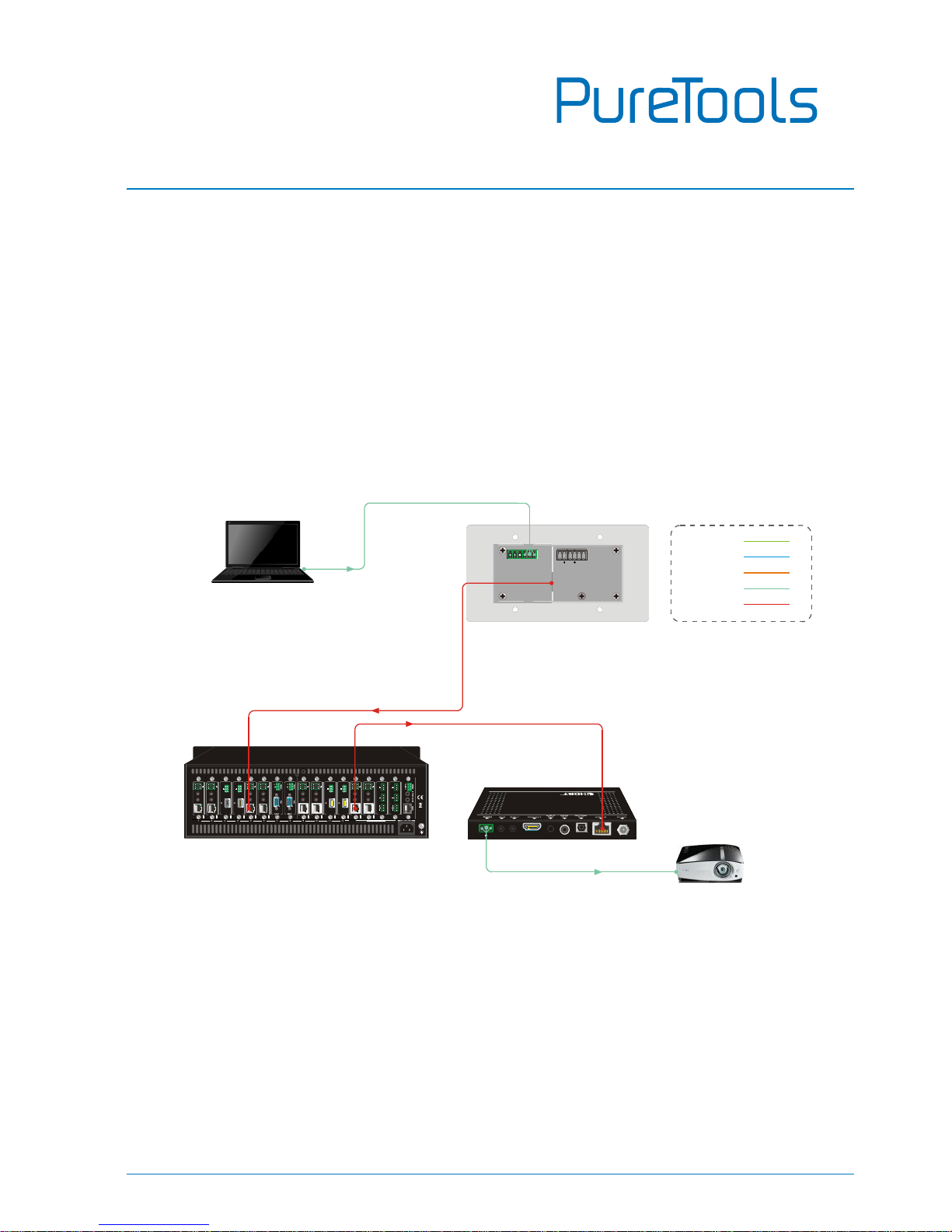
There are two RS232 control modes switching via sending 50779% or 50780%.
① Control this PT-HDBT-701-TXWP and far-end third-party device (such as
Projector) device by the local PC, and the connection diagram shown as below:
Tx Rx 12V 12V
RS232IN OUT
PoH IN
HDBT OUT
OUTPUTS 13~16
AUDIO
MIC IN AUDIO OUT
RL
MIX OUT
RL
OUTPUT
4K
Tx Rx
RL
IR OUTIR IN
RS232 AUDIO
HDBaseT
OUTPUT
4K
Tx Rx
RL
IR OUTIR IN
RS232 AUDIO
HDBaseT
OUTPUT
4K
Tx Rx
RL
IR OUTIR IN
RS232 AUDIO
HDBaseT
OUTPUT
4K
Tx Rx
RL
IR OUTIR IN
RS232 AUDIO
HDBaseT
OUTPUT
HDMI
AUDIO
L R
4K
OUTPUT
HDMI
AUDIO
L R
4K
OUTPUT
HDMI
AUDIO
L R
4K
OUTPUT
HDMI
AUDIO
L R
4K
4K
RS232 AUDIO
Tx Rx
RL
INPUT
IR OUTIR IN
HDBaseT
4K
RS232 AUDIO
Tx Rx
RL
INPUT
IR OUTIR IN
HDBaseT
4K
RS232 AUDIO
Tx Rx
RL
INPUT
IR OUTIR IN
HDBaseT
4K
RS232 AUDIO
Tx Rx
RL
INPUT
IR OUTIR IN
HDBaseT
AUDIO
MIC IN AUDIO OUT
RL
MIX OUT
RL
Tx Rx
Receiver
Projector
Matrix
PT-HDBT-701-TXWP
PC
1080P 70m
4K 40m
HDMI:
HDBaseT:
RS232:
Audio:
VGA:
Page 15
User Manual
PT-HDBT-701-TXWP
10
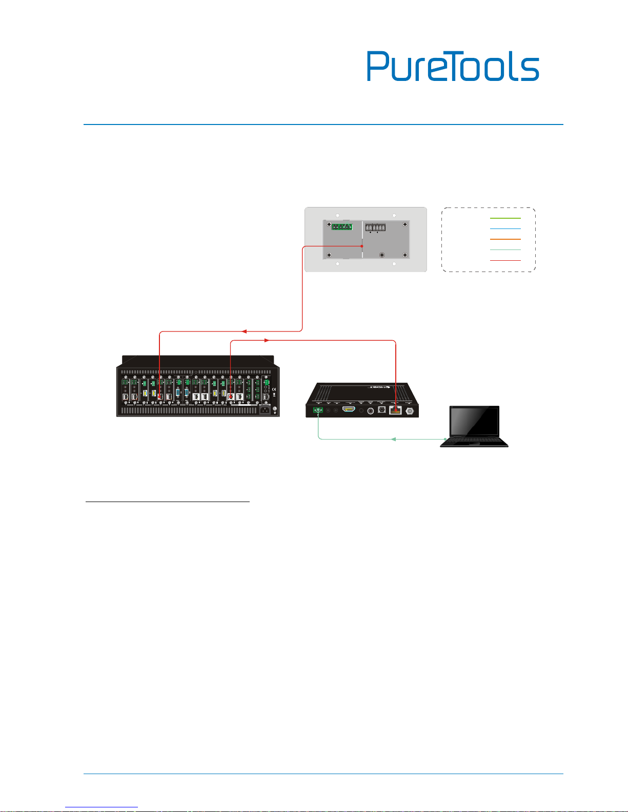
② Control the PT-HDBT-701-TXWP by the remote PC which is connected with
Receiver.
The RS232 control mode can be chosen via RS232 commands, please refer to the
5.3.1 Control Mode Switching for more details.
Tx Rx 12V 1 2V
RS232INOUT
PoH IN
HDBT OUT
OUTPUTS 13~ 16
AUDIO
MIC IN AUDIO OUT
RL
MIX OUT
RL
OUTPUT
4K
Tx Rx
RL
IR OUTIR IN
RS232 AUDIO
HDBaseT
OUTPUT
4K
Tx Rx
RL
IR OUTIR IN
RS232 AUDIO
HDBaseT
OUTPUT
4K
Tx Rx
RL
IR OUTIR IN
RS232 AUDIO
HDBaseT
OUTPUT
4K
Tx Rx
RL
IR OUTIR IN
RS232 AUDIO
HDBaseT
OUTPUT
HDMI
AUDIO
L R
4K
OUTPUT
HDMI
AUDIO
L R
4K
OUTPUT
HDMI
AUDIO
L R
4K
OUTPUT
HDMI
AUDIO
L R
4K
4K
RS232 AUDIO
Tx Rx
RL
INPUT
IR OUTIR IN
HDBaseT
4K
RS232 AUDIO
Tx Rx
RL
INPUT
IR OUTIR IN
HDBaseT
4K
RS232 AUDIO
Tx Rx
RL
INPUT
IR OUTIR IN
HDBaseT
4K
RS232 AUDIO
Tx Rx
RL
INPUT
IR OUTIR IN
HDBaseT
AUDIO
MIC IN AUDIO OUT
RL
MIX OUT
RL
Tx Rx
Receiver
Matrix
PT-HDBT-701-TXWP
PC
1080P 70m
4K 40m
HDMI:
HDBaseT:
RS232:
Audio:
VGA:
Page 16

User Manual
PT-HDBT-701-TXWP
11
5.2 RS232 Control Software
Installation Copy the control software file to the control PC.
Uninstallation Delete all the control software files in corresponding file path.
Basic Settings:
First, connect PT-HDBT-701-TXWP with all input devices and output devices needed,
then to connect it with a computer which is installed with RS232 control software.
Double-click the software icon to run this software.
Here we take the software CommWatch.exe as example. The icon is showed as below:
Page 17
User Manual
PT-HDBT-701-TXWP
12
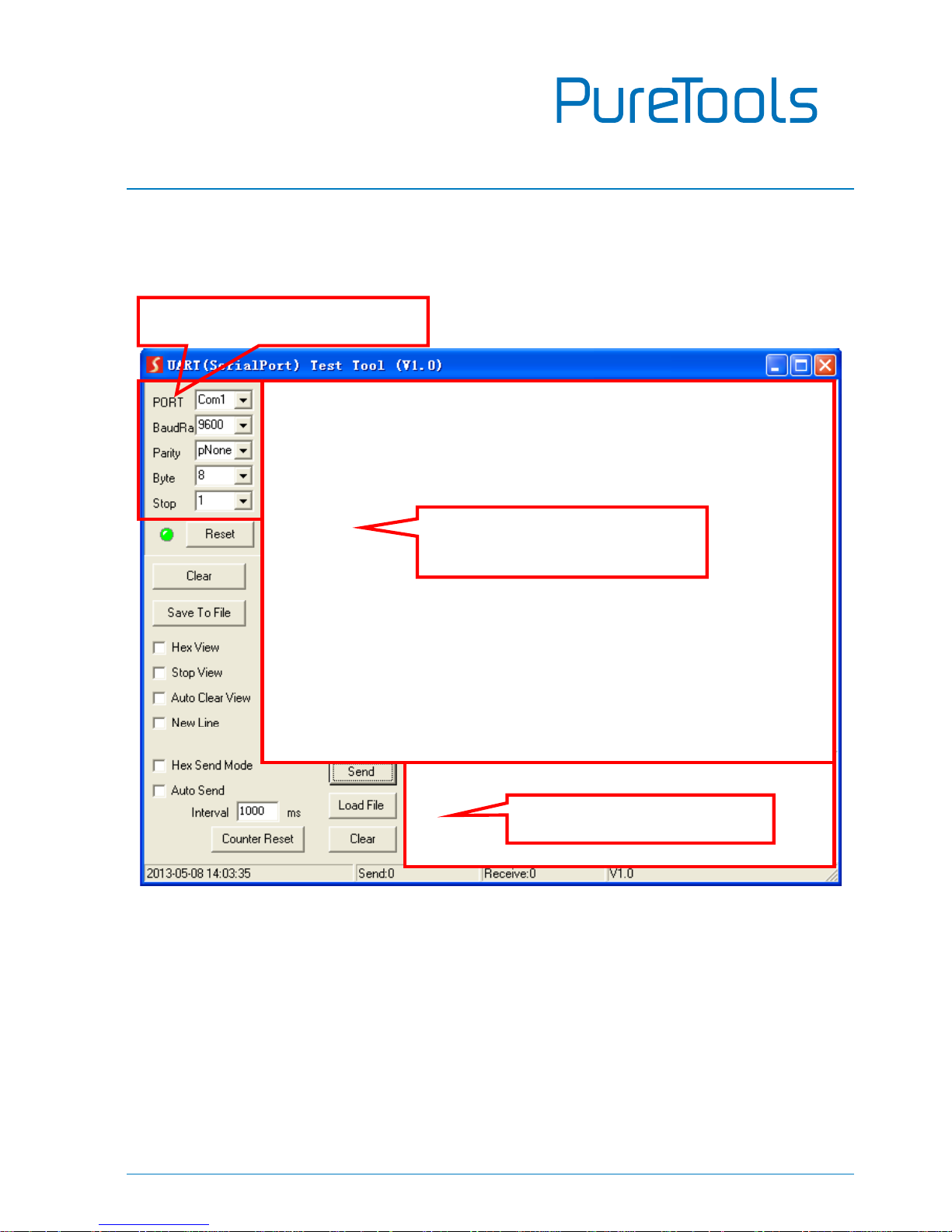
The interface of the control software is showed as below:
Please set the parameters of COM number, bound rate, data bit, stop bit and the
parity bit correctly, and then you are able to send command in Command Sending
Area.
Parameter Configuration area
Monitoring area, indicates if
the command sent works.
Command Sending area
Page 18
User Manual
PT-HDBT-701-TXWP
13
5.3 RS232 Command
Communication protocol: RS232 Communication Protocol
Baud rate: 9600 Data bit: 8 Stop bit: 1 Parity bit: none
5.3.1 Control Mode Switching
Command
Function
Feedback Example
50779%
Switch to RS232 mode 1(Default),
control scaler switcher and the far-end
third-party device.
RS232 Mode 1: RS232
Control Scaler & Remote.
50780%
Switch to RS232 mode 2, control the
scaler switcher from remote.
RS232 Mode 2:RS232 &
Remote Control Scaler
5.3.2 Signal Switching
Command
Function
Feedback Example
50770%
Enable auto-switching
Auto Switching
50771%
Disable auto-switching
Manual Switching
50702%
Switch to HDMI input
Switch to HDMI
50704%
Switch to VGA input
Switch to VGA
5.3.3 VGA Scaling Configuration
The default output resolution for VGA is 1920x1080. Below is a list of the output
resolutions the built-in scaler can output.
Command
Function
Feedback Example
50632%
Check the output resolution
Resolution: xx
50619%
Change the resolution to 1360X768
HD
Resolution: 1360x768
50626%
Change the resolution to 1024X768
XGA
Resolution: 1024x768
Page 19
User Manual
PT-HDBT-701-TXWP
14
Command
Function
Feedback Example
50627%
Change the resolution to 1280X720
720P
Resolution: 1280x720
50628%
Change the resolution to 1280X800
WXGA
Resolution: 1280x800
50629%
Change the resolution to 1920X1080
1080P
Resolution: 1920x1080
50620%
Change the resolution to1920X1200
WUXGA
Resolution: 1920x1200
50621%
Change the resolution to1600X1200
UXGA
Resolution: 1600x1200
5.3.4 HDCP Compliance
Command
Function
Feedback Example
50790%
Set the HDCP status of HDMI output
socket to Active
HDCP Active
50793%
Check HDCP status
HDCP Off/ HDCP On/
HDCP Active (default)
5.3.5 VGA Image Adjustment
Command
Function
Feedback Example
50636%
Check the brightness
Brightness: xx (xx=00~99)
502xx%
Set the brightness to xx.
Brightness: xx (xx=00~99)
50637%
Check the contrast
Contrast: xx (xx=00~99)
503xx%
Set the contrast to xx.
Contrast: xx (xx=00~99)
Page 20

User Manual
PT-HDBT-701-TXWP
15
Command
Function
Feedback Example
50638%
Check the saturation
Saturation: xx (xx=00~99)
504xx%
Set the saturation to xx.
Saturation: xx (xx=00~99)
50639%
Check sharpness
Sharpness: xx (xx=00~99)
505xx%
Set the sharpness to xx.
Sharpness: xx (xx=00~99)
50606%
Auto-adjust the input parameter
VGA Input Auto
50640%
Check the color temperature
Color Temperature: xx (xx
can be medium, warm,
user, or cool.)
50607%
Adjust the color temperature
Color Temperature: xx (xx
can be medium, warm,
user, or cool.)
50635%
Check the image aspect ratio
Aspect Ratio: xx (xx can be
16:9, 4:3, or auto.)
50608%
Set the aspect ratio
Aspect Ratio: xx (xx can be
16:9, 4:3, or auto.)
50633%
Check the picture mode
Picture Mode: xx (xx can be
dynamic, standard, mild, or
user.)
50614%
Set the picture mode
Picture Mode: xx (xx can be
dynamic, standard, mild, or
user.)
50707%
Check the present resolution and
polarity
1920x1080
Hpolarity:1
Vpolarity:0
50705%
Change the horizontal polarity to the
opposite
Hpolarity:0/1
50706%
Change the vertical polarity to the
opposite
Vpolarity:0/1
50678%
Enable screen output adjusting
Enter Output Position
Adjust
50679%
Disable screen output adjusting
Exit Output Position Adjust
Page 21
User Manual
PT-HDBT-701-TXWP
16
Command
Function
Feedback Example
50670%
Move the image to left
Output Position Adjust X
xx
50671%
Move the image to right
Output Position Adjust X
xx
50672%
Move the image up
Output Position Adjust Y
xx
50673%
Move the image down
Output Position Adjust Y
xx
50674%
Pull left from right side (decrease
image width)
Output Width Adjust xx
50675%
Stretch right from right side (increase
image width)
Output Width Adjust xx
50676%
Stretch upwards from bottom side
(decrease image height)
Output Height Adjust xx
50677%
Stretch downwards from bottom side
(increase image height)
Output Height Adjust xx
5.3.6 EDID Configuration
Command
Function
Feedback Example
50772%
EDID pass-through (default)
EDID: bypass mode
50773%
Set EDID data to 1080P PCM 2.0ch
EDID:1080P&PCM 2ch
50774%
Set EDID data to 1080P Dolby 5.1
EDID:1080P&5.1ch
50775%
Set EDID data to 1080P3D Dolby 5.1
EDID:1080P3d&5.1ch
50776%
Set EDID data to 1080i PCM 2.0ch
EDID:1080i&PCM 2ch
50777%
Set EDID data to 4Kx2K PCM 2.0ch
EDID:4K&PCM 2ch
50778%
Check EDID data
EDID: bypass mode
EDID:1080P&PCM 2ch
EDID:1080P&5.1ch
EDID:1080P3d&5.1ch
EDID:4K&PCM 2ch
50799%
Program EDID file, send EDID data
within 10s
Waiting for edid within 10
secs!
Page 22
User Manual
PT-HDBT-701-TXWP
17
Note: EDID commands are for HDMI sources only.
5.3.7 Device Configuration
Command
Function
Feedback Example
50698%
Software upgrading
50699%
Check the software version
Version Vx.x.x
50617%
Restore factory default
Page 23
User Manual
PT-HDBT-701-TXWP
18
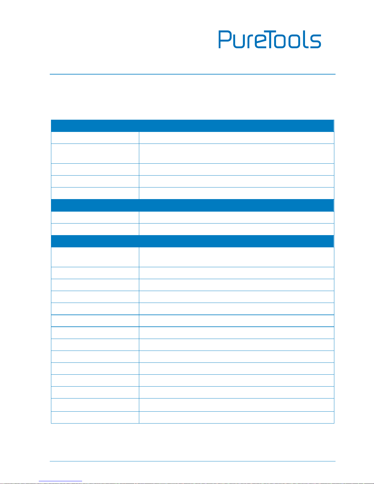
6. Specification
Input & Output
Input
(1) HDMI; (1) VGA; (1) AUDIO; (1) 12V POWER ;
Input Connector
(1) 19-pin Type A female HDMI; (1) HD-15 VGA; (1)
3.5mm mini jack; (1) 2-pin Pluggable Terminal Block
Output
(1) HDBaseT; (1) 12V POWER
Output Connector
(1) RJ45; (1) 2-pin Pluggable Terminal Block
Transmission Mode
HDBaseT
Control Parts
Control Ports
(1) FIRMWARE; (1) RS232
Control Connector
(1) Micro USB; (1) 3-pin Pluggable Terminal Block
General
Video Resolution
VGA - up to 1920 x 1080@60Hz;
HDMI - up to 4K/UHD@ 60Hz 4:2:0
Audio Impedance
>10Ω
Frequency Response
20Hz~20KHz
SNR
>85db@20Hz~20KHz
Transmission Distance
1080p ≤ 70M; 4Kx2K ≤ 40M
Bandwidth
10.2Gbps
HDMI Standard
Support HDMI1.4 and HDCP complaint
External Power Supply
Input:100V~240V AC; Output: 12VDC 2A
Max Consumption
9.6W
Operation Temperature
-10 ~ +40℃
Storage Temperature
-15 ~ +55℃
Relative Humidity
10% ~ 90%
Dimension (W*H*D)
151mm x 80mm x 44mm
Net Weight
258g
Page 24
User Manual
PT-HDBT-701-TXWP
19
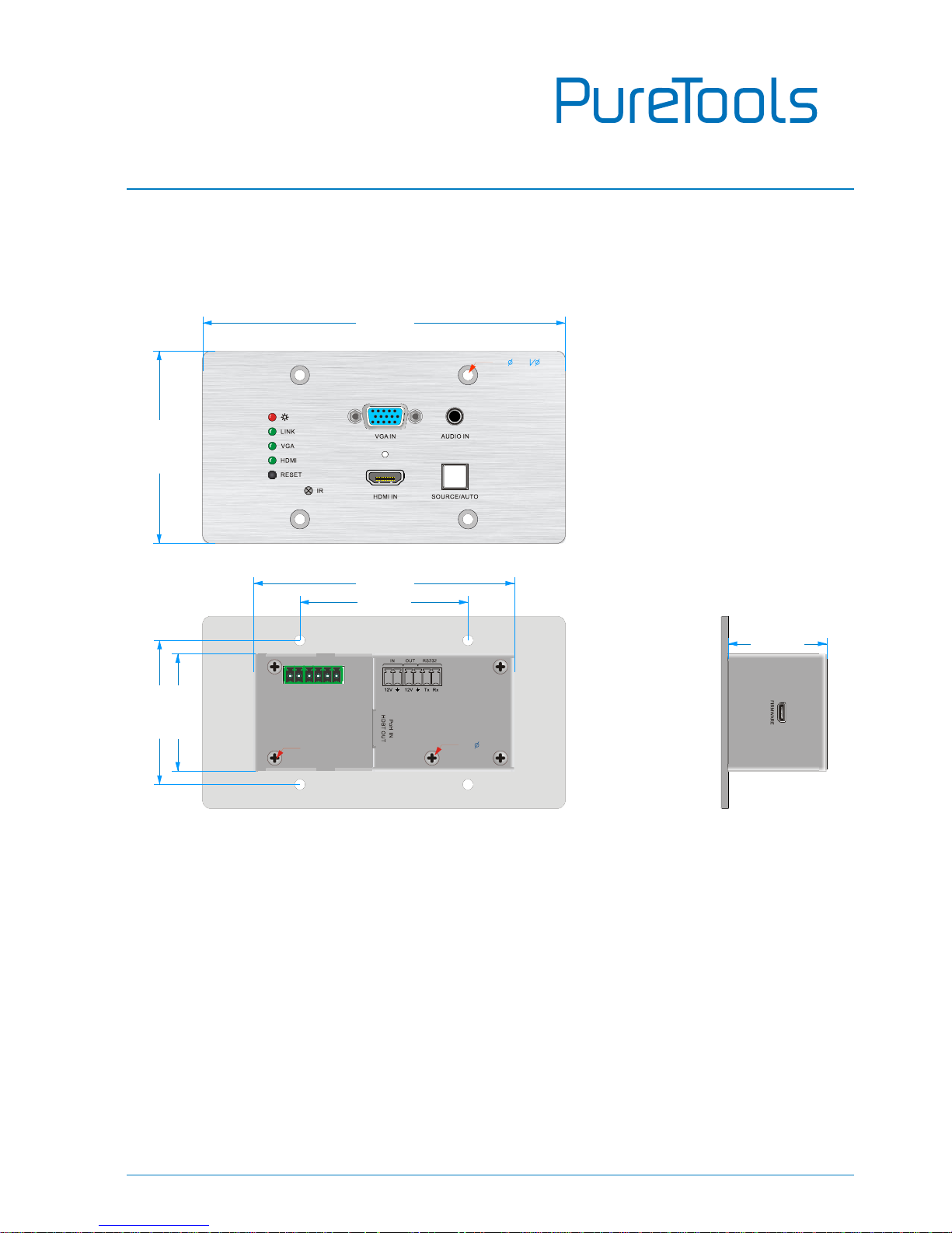
7. Panel Drawing
151.00 mm
8
0
.
0
0
m
m
4
8
.
8
0
m
m
108.60 mm
41.10 mm
70.00 mm
6
0
.
0
0
m
m
4- 4.5 8x90°
2-M3
3- 3.5
Page 25

User Manual
PT-HDBT-701-TXWP
20
8. Troubleshooting & Maintenance
Problems
Potential Causes
Solutions
Color losing or no video
signal output in HDMI
display
The connecting cables
may not be connected
correctly or it may be
broken
Check whether the cables
are connected correctly
and in working condition.
No HDMI signal output in
the device while local
HDMI input is in normal
working state
Output image with white
noise.
POWER indicator doesn’t
work or no respond to
any operation
Loose or failed power
cord connection
Ensure the power cord
connection is good
If your problem persists after following the above troubleshooting steps, seek further
help from authorized dealer or our technical support.
Page 26

User Manual
PT-HDBT-701-TXWP
21
9. After-Sales Service
If there appear some problems when running the product, please check and deal with
the problems referring to this user manual. Any transport costs are borne by the users
during the warranty.
1) Product Limited Warranty: The product will be free from defects in materials and
workmanship for two years (The purchase invoice shall prevail).
Proof of purchase in the form of a bill of sale or receipted invoice which is
evidence that the unit is within the Warranty period must be presented to obtain
warranty service.
2) What the warranty does not cover (servicing available for a fee):
Warranty expiration.
Factory applied serial number has been altered or removed from the product.
Damage, deterioration or malfunction caused by:
Normal wear and tear.
Use of supplies or parts not meeting our specifications.
No certificate or invoice as the proof of warranty.
The product model showed on the warranty card does not match with the
model of the product for repairing or had been altered.
Damage caused by force majeure.
Servicing not authorized by distributor.
Any other causes which does not relate to a product defect.
Delivery, installation or labor charges for installation or setup of the product.
3) Technical Support: For any questions or problems, contact your distributor or
reseller and tell them the respective product name and version, the detailed
failure situation as well as the formation of the cases.
Page 27

User Manual
PT-HDBT-701-TXWP
Page 28

User Manual
PT-HDBT-701-TXWP
Asking for Assistance
Technical Support:
Phone: +49 5971 800299 - 0
Fax: +49 5971 800299 – 99
Technical Support Hours:
8:30 AM to 5:00 PM Monday thru Thursday
8:30 AM to 4:00 PM Friday
Write to:
PureLink GmbH
Von-Liebig-Straße 10
D - 48432 Rheine
www.purelink.de
 Loading...