


PURESTREAM
MINI-CUBE
BY FRIULAIR
QBS Air Cooled Water Chiller
User Manual

Code
Revision
Edition
Changes
7425MUM651
02
02/2018
Editions Record
Original instructions: ITALIAN
EN Translation of the original instructions

Dear Customer,
Thank you for the trust you have placed in us. Please read this manu al carefully to obtain the best
performance from our product.
In order to avoid incorrect operating conditions a nd danger for the operators, it is essential that you
follow the directions meticulously as well as the current accident -prevention laws in the country of
use.
Each QBS chiller is rigorously tested before being packed.
This verifies that there are no manuf acturing defects and that the machine performs correctly the
functions for which it was designed.
This manual must be kept for future reference and is an integral part of the chiller you have
purchased.
Due to continuous technical development, we reserve the right to make the necessary modifications
without any obligation to give advance notice.
Do not hesitate to contact us if you have any problems or need more information.
The product identification plate, located on the side of the chiller, contains all essential information
about the machine.
You will have to give this data to the manufacturer, or reseller, wh enever you request information,
replacement parts, etc., during the warranty period.
Removing or tampering with the identification plate will void the warranty.
Warranty conditions:
For 12 months from the commissioning date, and no more than 14 months fr om the shipping date, any
parts that were originally defective will be repaired or replaced at no charge. Exp enses for transport
and travel, room and board for our technicians are excluded.
The warranty excludes any liability for direct or indirect damage to persons, a nimals and/or property
that are caused by incorrect use or inadequate maintenance and is exclusively limited to
manufacturing defects.
The right to service under the warranty is secondary to your faultless observance of the installation,
use and maintenance instructions in this manual.
The warranty will be voided immediately if the chiller is modified or tampered w ith, even slightly.
When requesting warranty service, you must provide the data on the product's identification plate.

SUMMARY
1 Safety Rules ............................................................................................................. 1
1.1 Definitions of the symbols used ........................................................................................ 1
1.2 Warnings .......................................................................................................................... 2
1.3 Proper use of the chiller .................................................................................................... 2
1.4 Instructions for using equipment under pressure conforming to PED Directive 2014/68/EU
3
2 Operation And Main Components .......................................................................... 4
2.1 Refrigerant circuit .............................................................................................................. 4
2.2 Water circuit ...................................................................................................................... 4
2.3 Fan ................................................................................................................................... 4
2.4 Condensation control ........................................................................................................ 4
2.5 Control of the water temperature....................................................................................... 5
2.6 Protecting the integrity of the machine .............................................................................. 5
2.7 QBS units: identification of the main components ............................................................. 5
2.8 Spare parts ....................................................................................................................... 6
3 Installation ................................................................................................................ 7
3.1 Transport .......................................................................................................................... 7
3.2 Storage ............................................................................................................................. 7
3.3 Place of installation ........................................................................................................... 7
3.3.1 Installation spaces ......................................................................................................................................... 8
3.4 Water connections ............................................................................................................ 8
3.4.1 Recommended water system ....................................................................................................................... 9
3.4.2 Use of ethylene glycol as a winter anti-freeze ............................................................................................ 10
3.4.3 Charging the water circuit........................................................................................................................... 10
3.5 Electrical connections ..................................................................................................... 11
4 Preliminary Checks And Start-Up ......................................................................... 12
4.1 Preliminary checks and preparation for the first start-up ................................................. 12
4.2 Startup ............................................................................................................................ 12
4.3 Start-up under critical conditions ..................................................................................... 12
5 Electronic Controller – QBS standard .................................................................. 13
5.1 Main functions of the electronic controller buttons and meanings of the icons ................ 13
5.2 Turning on and off ........................................................................................................... 14
5.3 Controlling water temperature ......................................................................................... 14
5.4 Changing the set point .................................................................................................... 14
5.5 Temperature display as detected by the probes .............................................................. 14
5.6 Locking and unlocking the keyboard ............................................................................... 15
5.7 Compressor operation hours ........................................................................................... 15
5.8 Setting the configuration parameters ............................................................................. 15
6 Autoadaptive Controller – QBS with EAA option ................................................ 16
6.1 Main functions of the electronic controller buttons and meanings of the icons ................ 16
6.2 Turning on and off ........................................................................................................... 16
6.3 Controlling water temperature – Standard setting ........................................................... 17
6.4 Changing the set point .................................................................................................... 17
6.5 Showing the temperature read by probe 1 (ambient temperature) .................................. 17
6.6 Showing the temperature read by probe 2 (outlet water temperature) ............................. 17
6.7 Locking/Unlocking the keyboard ..................................................................................... 18
6.8 Alarms ............................................................................................................................ 18
6.9 Setting configuration parameters .................................................................................... 18
6.10 Table of standard parameters configuration .................................................................... 19

6.11 Alternative method of temperature regulation ................................................................. 19
6.1 Calibration of the safety devices and type of rearm ......................................................... 20
6.2 Rearming the high-pressure pressure switch .................................................................. 21
7 Operating Limits .................................................................................................... 22
8 SEPR - SEASONAL ENERGY PERFORMANCE RATIO ACCORDING TO
COMMISSION REGULATION (EU) 2016/2281 ................................................................ 22
9 Maintenance, Inspections And Periodic Checks ................................................. 23
10 Troubleshooting ..................................................................................................... 24
11 Dismantling The Chiller ......................................................................................... 26
12 Water Diagrams ...................................................................................................... 27
13 Refrigerant Diagrams............................................................................................. 28
14 Dimensional Drawings........................................................................................... 29

Read this use and maintenance manual carefully before performing any repairs on the
chiller.
Warnings of a general character; risk of danger or possibility of damaging the machine,
pay particular attention to the phrase following this symbol.
Risk of electrical danger; the phrase highlights conditions that could be fatal. Follow the
instructions provided meticulously.
Risk of danger; component or system under pressure.
Risk of danger; component or system that can reach high temperatures during operation.
Risk of danger; it is absolutely forbidden to use water to extinguish fires near or on the
chiller.
Risk of danger; it is absolutely forbidden to operate the machine with the panel
open.
Service that can be performed by the machine’s operator, if qualified (1).
Water input connection point.
Water output connection point.
Dispose of each type of material in accordance with the requirements of the
country of use.
NOTE
Phrases to be emphasized that do not contain safety rules.
SAFETY RULES
1.1 DEFINITIONS OF THE SYMBOLS USED
1
7425MUM651 Model: QBS - Use and Maintenance Manual Rev. 02
1

This chiller has been carefully designed and constructed to be environmentally
friendly:
• Refrigerants without CFC;
• Expanded foam insulation without CFC;
• Energy-saving techniques;
• Reduced noise;
• The chiller and its packing materials are recyclable.
In order not to hinder our efforts, the user is required to obey the simple ecological
warnings indicated by this symbol.
Only qualified persons may use and maintain electrically-powered equipment.
Before commencing maintenance operations ensure no parts of the machine a re
live and it cannot be re-connected to the electrical power supply.
The QBS chillers contain R134A refrigerant.
Operations on the cooling circuit must only be performed by specialist personnel with
suitable equipment.
Any modifications to the machine or related operating parameters not previously
verified and authorized by the Manufacturer may be hazardous and will invalidate
the guarantee.
Do not use water to extinguish fires near or on the chiller.
Proper use requires conforming to the installation conditions and limits of ope ration (see
sections 3.5 and 7). In particular:
• Power voltage and frequency;
• Pressure, temperature of incoming water;
• Water flow rate;
• Surrounding temperature.
(1) These are persons with the experience, technical preparation and knowledge of standards and
regulations who are qualified to perform the necessary actions and able to recognize and avoid
possible dangers while handling, installing, using and maintaining the machine.
1.2 WARNINGS
1.3 PROPER USE OF THE CHILLER
QBS units are packaged air-cooled water chillers.
They are intended for use in industrial process or air -conditioning systems requiring chilled water.
Any other use is considered as incorrect.
The manufacturer is not liable for damage resulting from inappropriate use; in all cases, the user is
liable for any resulting hazards.
The chiller has been tested and completely assembled. The user must only make the connections to
other systems, as described in the chapters that follow.
7425MUM651 Model: QBS - Use and Maintenance Manual Rev. 02
2

1.4 INSTRUCTIONS FOR USING EQUIPMENT UNDER PRESSURE CONFORMING TO
PED DIRECTIVE 2014/68/EU
The proper use of equipment under pressure is an essential prerequisite for ensuring safety.
To this end, the user must proceed as follows:
• Use the equipment properly within the temperature limits shown in the operating limits stated
on the manufacturer’s name/data plate;
• Do not solder on the exchan gers or refrigerant fluid pipes;
• Do not install the equipment in insufficiently ventilated rooms, areas exp osed to sources of heat
or near inflammable substances;
• During operation, the equipment must not be subjected to vibrations th at could cause fatigue
failures;
• Keep the documentation attached to the equipment (user manual, declaration of conform ity,
etc.) for future reference;
• The maximum working pressure stated on the manufacturer’s data plate must not be exceeded.
Prior to use, the user must fit safety/pressure relief devices.
7425MUM651 Model: QBS - Use and Maintenance Manual Rev. 02
3

2
OPERATION AND MAIN COMPONENTS
2.1 REFRIGERANT CIRCUIT
QBS chillers use a vapour-compression cycle in a refrigerant circuit that essentially consists of the
following components: evaporator, compressor, condenser, lamination device (capillary tube).
Evaporator: heat exchanger (tube and fins) to enable heat exchange between the water and the
refrigerant liquid without them coming into contact with each other. The water is cooled when it
passes through the evaporator.
Compressor: compresses the steam from the evaporator to send it to the condenser at a higher
pressure.
Condenser: tube and fins exchanger to enable heat exchange between the refrigerant and the air; it
creates refrigerant gas condensation transferring the gas refrigerant condensation heat to the air
(which flows externally); high pressure refrigerant liquid is thus produced.
Lamination device: reduces the pressure of the liquid refrigerant coming from the condenser, which
is then sent to the evaporator.
Thanks to these components, the vapour-compression cycle works as follows: the refrigerant liquid
evaporates in the evaporator, chilling the water; the refrigerant vapours a re then aspirated from the
compressor, which compresses them and sends them to the condenser under high pressure; here,
thanks to a flow of forced air from the fans, the high-pressure refrigerant gas is cooled, making it
condensed and undercooled.
The flow of refrigerant liquid then passes through the lamination valve (thermostatic expansion
valve), which drastically reduces its pressure: the refrigerant liquid returns to the evaporator at a
reduced pressure where it again evaporates, taking heat from the water.
The refrigerant circuit also includes a water pump, which ensures the flow of water to be chilled by
evaporation, and the fan which ensures the condenser is cooled.
2.2 WATER CIRCUIT
The water circuit mainly consists of a pump, evaporator, tank.
The water flows into the evaporator first where it is cooled, then into the tank, and is then suctioned
by the pump which sends it to the system (see Water diagram section 11).
All QBS units have an open circuit with a tank at atmospheric pressure.
See chapter 11 Water diagram.
2.3 FAN
The fan forces air through the condenser fins to remove the refrigerant gas condensation heat,
therefore limiting the pressure inside the condenser.
QBS chillers are equipped with axial fans and have internal heat protection for the motor windings.
2.4 CONDENSATION CONTROL
When the ambient air temperature decreases, air flow cooling capacity increases slightly, causing a
reduction in pressure inside the condenser; to limit this decrease in condensation pressure from falling
below acceptable limits for good cooling circuit operation the fan stops temporarily.
7425MUM651 Model: QBS - Use and Maintenance Manual Rev. 02
4

04 High pressure switch
06 Compressor
08 Condenser
9.1 Fan
10 Refrigerant filter
11 Capillary tube
12 Temperature probe
17 Electronic controller
18 Evaporetor
22 Disconnector switch
61 Power input
90 Pump
91 Tank
93 Level indicator
95 Water input
96 Water output
97 Drain
99 Pressure plug
2.5 CONTROL OF THE WATER TEMPERATURE
The purpose of the chiller is to maintain the temperature of the water produced within a desired
interval as the load on the system varies; this is handled by an electronic controller and a temperature
probe that turn the compressors on and off appropriately (see also sections 5.3) .
2.6 PROTECTING THE INTEGRITY OF THE MACHINE
In addition to controlling the temperature, the electronic controller uses pressure switches, thermostats
and timers to prevent and handle situations that could compromise the integrity of the machine (also
see Chapter 6 Safety Devices).
2.7 QBS UNITS: IDENTIFICATION OF THE MAIN COMPONENTS
7425MUM651 Model: QBS - Use and Maintenance Manual Rev. 02
5

2.8 SPARE PARTS
Spare parts list is printed on a dedicated sticker applied inside the chiller. On this sticker each spare
part is identified with its ID Number and related Spare Part Number. Here below the cross reference
table between ID Number and exploded drawings Ref. With their description and quantity installed
inside chillers.
NOTE To order the suggested spare parts or any other part, it is necessary to quote the data
reported on the identification plate.
7425MUM651 Model: QBS - Use and Maintenance Manual Rev. 02
6

Always keep the chiller vertical: turning it upside down can irreparably damage several
parts of the unit.
Handle with care. Violent falls can cause irreparable damage.
The centre of the machine is approximately its centre of gravity. In any case, when handling
the machine with a forklift truck or pallet jack, always check its stability before lifting.
The packing material is recyclable.
Dispose of each type of material in accordance with the requirements in the
country of use.
Warning! The QBS 001÷002 models are suitable for indoor installation only.
3
INSTALLATION
3.1 TRANSPORT
The units are supplied packed in a cardboard box on a wooden pallet.
After checking that the packing is undamaged, position the unit near the installation site and unpack
it.
3.2 STORAGE
Protect the machine from bad weather, even if packed.
Always keep the chiller vertical, even when in storage. Turning it ups ide down can irreparably
damage several parts of the unit.
If not used, the chiller can be stored packed in an enclosed plac e, free of dust, with a maximum
temperature of 50 °C//122°F and specific humidity of not higher than 90%.
3.3 PLACE OF INSTALLATION
To determine the best place to install the unit, it is important to consider the following aspects:
• The dimensions and source of the water pipes;
• The location of the power supply;
7425MUM651 Model: QBS - Use and Maintenance Manual Rev. 02
7

Attention! If the machine is installed outside, it could find itself at a temperature lower
than 0°C//32°F, when stopped; the formation of ice could damage the
evaporator. If you do not intend to drain the machine during the winter, you
must add anti-freeze to the water circuit (see paragraph 3.4.3 Use of
ethylene glycol as a winter anti -freeze).
QBS 001÷002
• 800mm/31inches on each side
Important! Install the mechanical water filter on its input: scum and impurities can
seriously damage the evaporator.
• The solidity of the support surface;
• Avoid any obstacles to the flow of the fan which could cause the recirculation of air to the
condenser;
• Avoid the possible reflection of sound waves: (do not install in narrow or tight spaces);
• Provide access for maintenance or repair (see paragraph 3.3.1 Installation spaces);
• Average air temperature in the chosen installation area (see Section 7 Operating limits).
3.3.1 Installation spaces
To ensure the good functioning of the unit and access for maintenance, you must respect the minimum
installation space shown in the figure in this paragraph. The exit of air from the fan must not be
obstructed. In any case, avoid all situations in which hot air can circulate between the output of the
fan and the intake of the machine. Contact our office to verify feasibility in all cases where one of the
preceding conditions cannot be met.
3.4 WATER CONNECTIONS
Connect the machine to the water pipes following the instructions located near its water fittings (see
figures).
The installation of outlet and inlet taps on the machine is recommended, which will enable machine
maintenance without emptying the entire system, and emptying of the machine only during winter
downtime.
7425MUM651 Model: QBS - Use and Maintenance Manual Rev. 02
8

We recommend an extraordinary cleaning of the mechanical water filter after the machine
has been running for the first week (also see Chapter 8 Maintenance, inspections and
periodic checks).
Warning! No naked flames should be used during water connection operations, in the
vicinity of or inside the unit.
QBS 001÷002
50 Hz
60 Hz
Diameter of the in/out water fittings
3/8” GAS FM
3/8” NPT FF
NOTE It is a good rule that the diameters of the arriving and departing pipes be not less than the
water fittings.
3.4.1 Recommended water system
QBS 001÷002 units come as standard with a tank at atmospheric pressure, pump and bypass; it is
advisable to also provide the water circuit with:
• A mechanical filter for water in the machine inlet pipes, with mesh no greater than 1mm;
• Machine inlet and outlet taps;
• Inlet and outlet pressure gauges and thermometers for water from the machine, to control its
operation.
Diagram of recommended water circuit for QBS 001÷002 models
7425MUM651 Model: QBS - Use and Maintenance Manual Rev. 02
9

Key
1
Tap
4
Thermometer
2
Mechanical filter
5
System/unit discharge
3
Pressure gauge
Outside air temperature [°C]
0
-5
-10
Outside air temperature [°F]
32
23
14
Percentage of ethylene glycol [%]
10
15
20
Attention! Maximum concentration of ethylene glycol allowed: 20%. For glycol concentrations
higher than 20%, contact our company's sales offices to make sure that the mechanical seal and
the pump motor are suitable for the type and concentration of fluid loaded in the hydraulic system
Attention! Make sure that the tube that draws the inlet water to the pump is almost always
fluid-filled. It is also recommend, at least in the very early re -start phase, to
close the liquid outlet port of the chiller to increase the pump's prevalence.
This will avoid premature failure of the impeller and will extend the life of
mechanical seal. Also, the engine will not overheat.
Water level indicator
3.4.2 Use of ethylene glycol as a winter anti-freeze
Instead of emptying the system in the winter, you can charge the syste m with a mixture of water and a
suitable percentage of ethylene glycol, chosen as a function of the lowest expected temperature of the
outside air.
Percentages of ethylene glycol recommended as a function of the expected temperature of the outside air
3.4.3 Charging the water circuit
• Check that the drain taps are turned off;
• Open the system interception devices;
• Feed the water from the filling inlet above the machine until the water reaches the required level
(near the transparent level indicator – see diagram). When the pump starts check the level
again and top up if necessary;
• Check for any leaks by examining the circuit.
7425MUM651 Model: QBS - Use and Maintenance Manual Rev. 02
10

The machine must be connected to the electricity following the electrical diagram and
conforming to the current laws and regulations in the place of installation.
Attention! Never change the internal electrical connections, as the warranty will be
immediately voided.
Important! Screw the wires solidly to the terminal strip of the cut-off switch and lock the
wire with a cable-gland.
Important! Make the cable entering the machine enters the cable-gland from below: this
prevents rain from dripping inside the machine.
Important! The earth connection is mandatory: connect the earth wire to the terminal
provided in the electrical panel. The ground wire must be longer than the other
wires so that it will be the last one to be pulled if the device holding the cable
loosens.
3.5 ELECTRICAL CONNECTIONS
• The voltage, frequency and number of phases must conform to the data shown on the machine's
identification plate;
• The power supply voltage must not vary by more than ±10% from its nominal value;
• The frequency must not vary by more than ±1% from its nominal value (±2% for brief periods) ;
• The imbalance between power phases must be <2%;
• Upstream from the electrical panel, install a differential switch (IDn=0.03A) (main power
switch) and slow-blow fuses with the specifications shown on the electrical diagram;
• Use wires of the section shown on the electrical diagram and in the following table .
7425MUM651 Model: QBS - Use and Maintenance Manual Rev. 02
11

Attention! Make sure that the tube that draws the inlet water to the pump is almost always
fluid-filled. It is also recommend, at least in the very early re -start phase, to
close the liquid outlet port of the chiller to increase the pump's prevalence.
This will avoid premature failure of the impeller and will extend the life of
mechanical seal. Also, the engine will not overheat.
4
PRELIMINARY CHECKS AND START-UP
4.1 PRELIMINARY CHECKS AND PREPARATION FOR THE FIRST START-UP
Before starting up the unit, it is a good idea to do the following:
• Check that the water shut-off valves are open;
• Verify the regular water level in the tank;
• Check that the surrounding temperature is in the range for the machine to function (see Chapter
7 Operating Limits);
• Check the cut-off switch on the machine switchboard is open;
• Check that the mains voltage matches the voltage on the machine's identification plate with a
tolerance of ±10%;
• Close the main power supply switch;
• Close the cut-off switch on the machine's electrical pa nel.
4.2 STARTUP
Connect the device power supply. Touch the for 4 seconds. The led will flash and turn off, the
chiller will switch on.
The controller will display the temperature of the water inside the tank - if it is higher than the set
value the compressor will start up.
To disable, touch the for 4 seconds. The led will flash and turn on, the chiller will switch off.
4.3 START-UP UNDER CRITICAL CONDITIONS
The consequence of starting up under critical conditions could be the intervention o f the high-pressure
pressure switch (to rearm the high-pressure pressure switch, see paragraph 6.2 Rearming the high-
pressure pressure switch).
To overcome this problem, you will have to reduce the thermal load on the machine by shutting off
some of the uses or, if this is not possible, by reducing the flow of water into the evaporator: partially
close the output tap from the chiller and restart the machine.
Operate the chiller under these conditions until the water temperature gradually returns within
operating limits; then, you can turn on the tap completely.
7425MUM651 Model: QBS - Use and Maintenance Manual Rev. 02
12

Button
Function
On/off button
Exit procedure
Setting setpoint
Access the menu
Down key
Up key
Display/Led
Function
Indicates the state of compressor :
On: compressor ON
Off: compressor OFF
Flashing: setting setpoint mode or compressor protection
Indicates the state of the fans :
On: fan ON
Off: fan OFF
Flashing: fan stopping
Auxliary led
Energy saving on
°Celsius unit
°Fahrenheit unit
Indicates the state of the chiller:
On: chiller OFF
Off: chiller ON
5
ELECTRONIC CONTROLLER – QBS STANDARD
The QBS 001÷002 electronic controller:
• Displays the temperature of the water exiting the water chiller;
• Enables the required temperature of the chilled water to be set (set point);
• Enables compressor activation and deactivation (standby) ;
• Controls on/off compressor operation depending on the temperature of the water measured with
the set point and upper differential (3°C//3K//5,4°F);
• Guarantees minimum compressor on/off times to maintain its integrity;
• Signals any faults in the temperature probe.
5.1 MAIN FUNCTIONS OF THE ELECTRONIC CONTROLLER BUTTONS AND MEANINGS
OF THE ICONS
7425MUM651 Model: QBS - Use and Maintenance Manual Rev. 02
13

Sign
Description
Type of rearm
iA
Multifunction input alarm
Pressure switch alarm
Manual
Pr1
Probe AI1 failure
Automatic
Pr2
Probe AI2 failure
Automatic
AL
Minimum temperature AI1 probe - Antifreeze
Automatic
AH
Maximum temperature AI1 probe
Automatic
COH
Superheated condenser
Automatic
CSd
Blocked condenser
Automatic
The display shows alarms like in the following table.
5.2 TURNING ON AND OFF
Connect the device power supply . Touch the for 4 seconds. The led will flash and turn off, the
chiller will switch on.
To disable, touch the for 4 seconds. The led will flash and turn on, the chiller will switch off.
5.3 CONTROLLING WATER TEMPERATURE
The QBS’s electronic controller regulates the outlet water temperature on the basis of a set point
value and an upper differential of 3°C//3K//5,4°F according to the following diagram:
5.4 CHANGING THE SET POINT
Touch the : the flashing led indicates that the setpoint can be changed . Use and
keys within 15 seconds to change the temperature setpoint. Touch key or do not
operate for 15 seconds to confirm the value. Otherwise, touch key, but any changes will not be
saved. The led will switch off and the device will exit the procedure.
5.5 TEMPERATURE DISPLAY AS DETECTED BY THE PROBES
• Make sure that the keyboard is not locked and that no procedure is in progress;
• Touch the key for 4 seconds: the display will show the first label available;
• Touch the or key to select a label Pb1/ Pb2;
• Touch the key to display the corresponding temperature;
• To exit the procedure, touch key or do not operate for 60 seconds;
• Touch the key.
7425MUM651 Model: QBS - Use and Maintenance Manual Rev. 02
14
5.6 LOCKING AND UNLOCKING THE KEYBOARD
To lock the keyboard proceed as follow:
• Make sure that the keyboard is not locked and that no procedure is in progress;
• Do not operate for 60 seconds: the display will show the message ”Loc” for 1 second and the
keyboard shall lock automatically.
To unlock the keyboard:
• Touch a key for 1 second: the display will show the message ”UnL” for 1 second.
5.7 COMPRESSOR OPERATION HOURS
To shoe the compressor operation hours:
• Make sure the keyboard is not locked and that no procedure is in progress;
• Touch the key for 4 seconds: the display will show the first label available;
• Touch the or key to select the label CH;
• Touch the key to display the corresponding compressor’s running hours.
To cancel the compressor operation hours:
• Make sure the keyboard is not locked and that no procedure is in progress;
• Touch the key for 4 seconds: the display will show the first label available;
• Touch the or key to select the label rCH;
• Touch the key;
• Touch the or key within 15 seconds to set a password0F
1
;
• Touch the key or do not operate for 15 seconds: the display will show a flashing ”--
--” for 4 seconds, after which the device will exit the procedure.
5.8 SETTING THE CONFIGURATION PARAMETERS
To access the procedure:
• Make sure no procedure is in progress;
• Touch the key for 4 seconds: the display will show ”PA”;
• Touch the key;
• Touch the or key within 15 seconds to set a password1F
• Touch the key or do not operate for 15 seconds: the display will show ”SP”.
To select a parameter:
• Touch the or key;
To set a parameter:
• Touch the key;
• Touch the or key within 15 seconds to set the value as desired;
• Touch the key or do not operate for 15 seconds.
To exit the procedure:
• Touch the key for 4 seconds or do not operate for 60 seconds (any changes will be
saved).
2
;
1
Contact our company.
2
Contact our company.
7425MUM651 Model: QBS - Use and Maintenance Manual Rev. 02
15

Button
Function
Setting setpoint
Down key
Access the menu
Up key
Display/Led
Function
Indicates the state of the fans:
On: fan ON
Off: fan OFF
Flashing: fan stopping
°Celsius unit
°Fahrenheit unit
Indicates the presence of alarms
After setting the parameter, suspend power supply flow to the device.
6
AUTOADAPTIVE CONTROLLER – QBS WITH EAA OPTION
The QBS 001÷002 electronic controller:
• Displays the temperature of the water exiting the water cooler;
• Enables the required temperature of the chilled water to be set (set point);
• Signals any faults in the temperature probe.
6.1 MAIN FUNCTIONS OF THE ELECTRONIC CONTROLLER BUTTONS AND MEANINGS
OF THE ICONS
6.2 TURNING ON AND OFF
Connect the device power supply. To turn on the instrument you have to supply it by the cut -off
switch. To turn it off it is enough to cut off the power supply by closing the cut -off switch.
The display will shows the outlet water temperature.
7425MUM651 Model: QBS - Use and Maintenance Manual Rev. 02
16

6.3 CONTROLLING WATER TEMPERATURE – STANDARD SETTING
The QBS’s electronic controller regulates the outlet water temperature in function of the ambient
temperature. The working setpoint will be relative to the temperature read by probe or temperature
read by probe 1 – working setpoint (without sign).
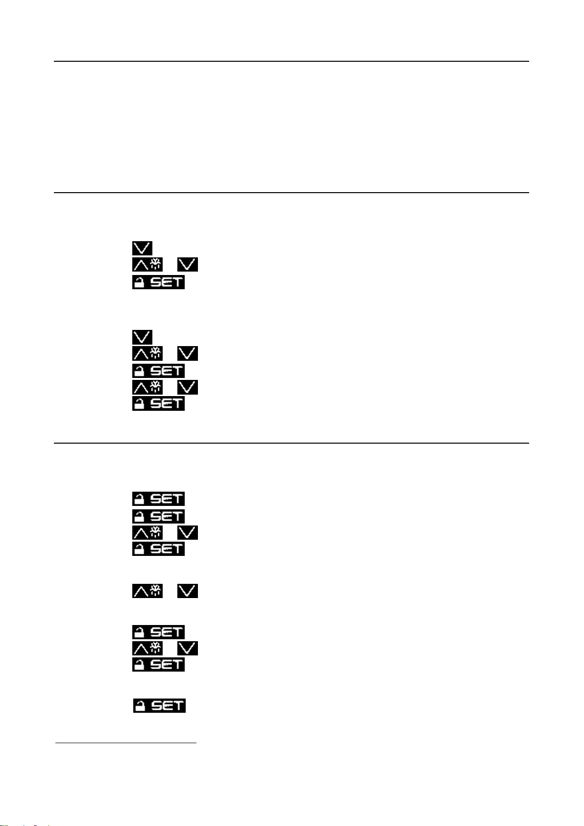
6.4 CHANGING THE SET POINT
Make sure the keyboard is not locked and no procedure is running.
To gain access the procedure:
• Press and 4 seconds and the display will show “PA”;
• Press ;
• Press or in 15 seconds to set the password2F
3
;
• Press or do not operate 15 seconds;
• Press and 4 seconds and the display will show “SP”, the first available parameter.
• Press or to scroll the parameter list until you reach “r0”;
• To select the parameter, press and use or in 15 seconds to modify the setting
value;
• Press to confirm the value or do not operate 15 seconds.
6.5 SHOWING THE TEMPERATURE READ BY PROBE 1 (AMBIENT TEMPERATURE)
Make sure the keyboard is not locked and no procedure is running.
• Press 2 seconds: the dispaly will show the first available label;
• Press or to select “Pb1”;
• Press to show the setting value.
6.6 SHOWING THE TEMPERATURE READ BY PROBE 2 (OUTLET WATER TEMPERATURE)
Make sure the keyboard is not locked and no procedure is running.
• Press 2 seconds: the dispaly will show the first available label;
• Press or to select “Pb2”;
Press to show the setting value.
3
Contact our company.
7425MUM651 Model: QBS - Use and Maintenance Manual Rev. 02
17

Code
Description
Type of rearm
AL1
Minimum temperature probe 1
(ambient temperature)
Automatic
AL2
Maximum temperature probe 2
(outlet water temperature)
Automatic
Pr1
Probe 1 error
Automatic
Pr2
Probe 2 error
Automatic
Loc
Keyboard and/or setpoint are locked
---
----
The quantity to show is not available
---
6.7 LOCKING/UNLOCKING THE KEYBOARD
Make sure the keyboard is not locked and no procedure is running.
• Press and 2 seconds: the display will show “Loc” 1 second.
If the keyboard is locked, you will not be allowed to:
• Show the temperature read by probe 1 and probe 2;
• Modify the working setpoint.
This operations provoke the visualization of the label “Loc” 1 second.
To unlock the keyboard:
• Press and 2 seconds: the display will show “UnL” 1 second.
6.8 ALARMS
The display will show the following code of alarm.
6.9 SETTING CONFIGURATION PARAMETERS
To gain access the procedure:
• Press and 4 seconds and the display will show “PA”;
• Press ;
• Press or in 15 seconds to set the password3F
• Press or do not operate 15 seconds;
• Press and 4 seconds and the display will show “SP”, the first available parameter.
• Press or to scroll the parameter list;
• To select a parameter, press and use or in 15 seconds to modify the setting
value;
• Press to confirm the value or do not operate 15 seconds.
4
;
4
Contact our company.
7425MUM651 Model: QBS - Use and Maintenance Manual Rev. 02
18

Parameter
Function
Factory setting
SP
Working setpoint
0°C//32°F
r0
Working setpoint differential
5K
r1
Minimum working setpoint
0°C//32°F
r2
Maximum working setpoint
25°C//77°F
r6
Type of working setpoint:
• Absolute setpoint r6=0
• Relative setpoint r6=1: temp. read by probe 1 – working setpoint
1
r7
Forced off of compressors
4°C//39,2°F
r8
Differential of parameter r7
[At r7+r8 value the compressor could be switched on]
2K
A1
Temperature the alarm of low temperature is activated AL1
4°C//39,2°F
A4
Temperature the alarm of high temperature is activated AL2
50°C//122°F
A10
Differential of parameter A1
[At A1+A10 value the alarm AL1 will be deactiveted]
2K
A11
Differential of parameter A4
[At A4-A11 value the alarm AL2 will be deactiveted]
5K
Parameter
Function
Suggested value
r1
Minimum working setpoint
6°C//42,8°F
r6
Type of working setpoint:
• Absolute setpoint r6=0
• Relative setpoint r6=1: temp. read by probe 1 – working setpoint
0
6.10 TABLE OF STANDARD PARAMETERS CONFIGURATION
Below there is a table of most important parameters and their factory setting. To modify the parameter
contact our company.
6.11 ALTERNATIVE METHOD OF TEMPERATURE REGULATION
The electronic controller allows to regulate the outlet working temperature with an absolute logic in
function of the temperature read by probe 1.
In that way, the SP value is the absolute regulation setpoint like in the following image.
To set this kind of working mode, please set the following values in that way (see paraghaph 5.9
Setting configuration parameters).
7425MUM651 Model: QBS - Use and Maintenance Manual Rev. 02
19
Dangerous situation
Safety device
Location
High condensation pressure
High-pressure switch
Compressor output pipe
Low water temperature
Anti-freeze thermostat
Water exit from the
evaporator
Frequent compressor start-ups
Anti-circulation timer
Electronic controller
Low water level in the tank
Water-level sensor
Tank
For some safety devices, once the cause of the alarm times out, the machine resumes
operation automatically as soon as the reset value is reached. Others must be manually
reset to restart the machine.
The following paragraph lists the characteristics of each safety device.
Safety device
Intervention value
Reset value
Type of rearm
High-pressure gauge
30 barg//435 psi
23 barg//334 psi
Manual
Anti-freeze thermostat
4°C//39,2°F
6°C//42,8°F
Semiautom.
Water-level sensor
--
--
Semiautom.
Anti-circulation timer*
5 min.
--
--
Safety Devices
QBS chillers have a series of safety devices that limit the machine's temperature and pressure values
to ensure that it operates within the expected limits and to avoid dangerous situations.
Here is a list of dangerous situations, including the relative safety device and its location.
Legend: n.a. not available – Opt.: optional
When they reach their calibration value, most of the security devices trigger an alarm managed by the
electronic controller.
6.1 CALIBRATION OF THE SAFETY DEVICES AND TYPE OF REARM
* This is a function of the electronic controller that prevents the same compressor from stopping and
starting too frequently: at least 5 minutes must elapse between one compre ssor’s power up and the
next.
7425MUM651 Model: QBS - Use and Maintenance Manual Rev. 02
20

Warning! The upper part of the compressor casing and discharge pipe are at a high
temperature.
Be especially careful when working in their vicinity.
High pressure switch
For this reason, when dealing with an intervention of the high-pressure
switch, it is necessary to:
A) Identify the cause of the rise in pressure (fan not working,
condensation coil dirty or obstructed, obstacles to the flow of
exiting air, operating temperature outside operating limits, etc.
(also see Chapter 9 Troubleshooting) and remove the cause, if
possible;
B) Wait until the high-pressure manometer falls below the reset
value (see the table, “Calibration of the safety devices and type
of rearm” in paragraph 6.1);
C) Rearm the pressure switch by pressing the red button: if you do
not hear a click, it is not rearmed;
D) Then rearm the electronic controller.
Attention! The high-pressure gauge stops the compressor while it keeps the condenser fan
running to lower the pressure in the condenser .
6.2 REARMING THE HIGH-PRESSURE PRESSURE SWITCH
The intervention of the high-pressure pressure switch is the only case in which, in addition to
manually rearming the electronic controller, it is also necessary to reset the pressure switch itself.
The high-pressure pressure switch is located in the compressor compartment on the uninsulated
copper pipe that goes from the compressors to the condensation coil; there is a manual-reset button on
top of it.
This can only be rearmed when the pressure in the circuit has fallen below the reset value (see table
Calibration of the safety devices and type of rearm in paragraph 6.1).
7425MUM651 Model: QBS - Use and Maintenance Manual Rev. 02
21

230V/1Ph/50Hz
Model QBS
001
002
SEPR
4,16
4,37
7
OPERATING LIMITS
The graphs show the limits for continuous operation of the QBS units, in relation to the temperature
of the water exiting the machine, and the temperature of the external air.
QBS 001÷002
8
SEPR - SEASONAL ENERGY PERFORMANCE RATIO
ACCORDING TO COMMISSION REGULATION (EU) 2016/2281
Only for units at 50Hz power supply.
22
7425MUM651 Model: QBS - Use and Maintenance Manual Rev. 02

To keep the machine running properly and providing the guaranteed performance required,
it is necessary to make some periodic checks.
Operation
Frequency
Execution
Check that the temperature of the water produced is in the
required interval
Daily
User
Check tank water level using level indicator – see section 3.4.3
Daily
Check for the presence of any alarm signals
Daily
Check the functioning of the fans
Monthly
Check that the temperature of the air is compatible with the
operating limits of the machine
Monthly
Clean the condensing coil with a jet of compressed air
Annual (1)
Specialized
personnel
Clean the water filter
Monthly(2)
Check that the subcooling and superheating values are,
respectively between 3÷5K//5,4÷9°F and 5÷7K//9÷12,6°F
Every 6 months
Check for traces of oil on the pipes of the refrigerant circuit
(symptom of refrigerant leaks)
Every 6 months
Check the tightness of the electrical terminals both inside the
electrical panel and on the terminal strips of the compressors
Yearly
Check the contacts of the contactors; if they show signs of
deterioration, replace them
Yearly
Check that the current absorbed by the machine is within the
values on the identification plate
Every 6 months
Attention! Before carrying out any maintenance on the unit or accessing internal parts,
make sure you have cut-off the electricity.
Attention! The upper part of the compressor housing and the output pipe are hot. Be
especially careful when working near them.
MAINTENANCE, INSPECTIONS AND PERIODIC CHECKS
9
(1) It may be necessary to carry this out more frequently in the case of particularly dirty environments.
(2) We recommend an extraordinary cleaning of the filter after the machine has been operating for the first
week.
(3) It is not necessary to do this if the system has been charged with an anti -freeze solution (water and a
suitable percentage of glycol) (see paragraph 3.4.3 Use of ethylene glycol as a winter anti -freeze).
7425MUM651 Model: QBS - Use and Maintenance Manual Rev. 02
23

Cause
Alarm or symptom
Solution
Execution
1. The unit does not start
Contacts of the main differential
switch are open
Electronic controller
off
Close the contacts
User
Unit's electrical panel cut -off switch
is open
Electronic controller
off
Close the contacts
User
Compressor timer active
The compressor icon
on the display of the
electronic controller is
flashing
Wait (5 mins at the most)
User
No consent from the service
thermostat
System water at
temperature (see
display)
Apply a thermal load to the
machine or lower the set
point
User
No consent from the antifreeze
thermostat
AL
Reset a temperature of the
water (setpoint) compatible
with the calibration of the
antifreeze thermostat
User
Service and anti-freeze probe
defective
AL
Check contacts and
replace, if necessary
Specialized
personnel
Water temperature probes defective
Pr1/Pr2
Check contacts and
replac e, if necessary
Specialized
personnel
Intervention of the main differential
switch
Electronic controller
off
Look for current leakage
inside the machine
Specialized
personnel
2. The compressor does not start
Intervention of the thermal
protection inside the compressor
The contactor of the
compressor is on but
the compressor is
stopped
Wait for cooling: check that
the compressor is working
under normal conditions.
Check for insufficient
refrigerant in the circuit (see
point 6).
Specialized
personnel
Contactor of the compressor off
The compressor icon
is on but the
compressor is stopped
Check the voltage at the
coil of the contactos of the
compressor and the
continuity of the coil itself
Specialized
personnel
3. The water pump does not make pressure and flow
The suction pipe of the pump is full
of air or the pressure drops on the
hydraulic circuit are too high
The water pump does
not work properly
Make sure that the tube that
draws the inlet water to the
pump is almost always fluid filled. It is also recommend,
at least in the very early restart phase, to close the
liquid outlet port of the
chiller to inc rease the
pump's pre valence (see
paragraph 3.4.3 Charging
the water circuit)
Specialized
personnel
TROUBLESHOOTING
10
24
7425MUM651 Model: QBS - Use and Maintenance Manual Rev. 02

Cause
Alarm or symptom
Solution
Execution
4. Intervention of the high pressure pressure switch
Condenser obstructed or
insufficient air flow-capacity
iA
Remove di rt from the
condenser and any obstacles
to the fl ow of air. Wait for the
pressu re to drop below the
reset val ue, then rearm the
high-pressure pressure switch
by pressi ng the button on top
of it (see figure in parag raph
6.2 ).
User
The unit has operated outside its
operating limits (such as air or
water too hot)
iA
If possible, restore conditions
that are compatible with t he
operating limits.
Reset the high pressure switc h
(pa ragraph 6.2).
User
Fan not working
iA
See point 4
Excessive refrigerant charge
High subcooling
(greater than
10K//18°F)
Drain excess refrigerant
Specialized
personnel
Presence of air or incondensable
gas in the refrigerant circuit
Presence of bubbles
on the flow peep hole,
also with subcooling
values greater than
5K//9°F
Drain the circuit, create
vacuum and recharge
Specialized
personnel
Refrigerant filter clogged or
thermostatic valve stuck
Pipe downstream from
the component
covered with frost
Check and replace
Specialized
personnel
5. Fan doesn't start
Very low outside air temperatures
and consequent intervention of the
condensation control
Fan icon off.
Condensation
pressure normal
The machine can working
anyway
6. The unit is working without ever stopping
Excessive thermal load
Reduce the thermal load.
Reduce the temperature of
the incoming water and/or
the flow-capacity of the exit
tap of the unit a little.
User
No refrigerant
See point 6
7. Compressor intake pipe covered with frost
No refrigerant
High overheating, low
underc ooling and high
output temperature of
the compressor.
Traces of oil on the
refrigerant circuit.
Check the chiller circuit with
a leak detector.
Repair any ruptures and
recharge the circuit.
Specialized
personnel
8. The unit stops and starts repeatedly; water temperature changes suddenly
Insufficient water flow rate
Check water flow rate.
Open the system tap fully.
If possible reduce system
feed leaks.
If possible add a pump in
series with suitable head.
Specialized
personnel
7425MUM651 Model: QBS - Use and Maintenance Manual Rev. 02
25

If the chiller is being dismantled, you must separate it into parts of homogeneous material.
The following table lists the main materials of the various components of the machine.
Part
Material
Refrigerant fluid
R134A, Oil
Panelling and supports
Carbon steel, epoxy paint
Chiller compressor
Steel, Copper, Aluminium, Oil
Evaporator
Copper
Condenser
Aluminium, Carbon Steel , Copper
Pipes
Copper
Fan
Aluminium, Copper, Steel
Valves
Steel, Bronze
Insulation
Synthetic rubber without CFC, EPS, Polyurethane
Pump
Steel, Copper
Tank
Stainless steel
Electrical wires
Copper, PVC
Electrical parts
PVC, Copper, Bronze
Dispose of refrigerant properly. Remove it from the chiller with suitable tools and
deliver it to authorized collection centres that will treat it and make it reusable.
DISMANTLING THE CHILLER
11
We recommend that you follow current safety norms for the disposal of each single material.
The refrigerant contains particles of lubrication oil from the chiller compressor.
7425MUM651 Model: QBS - Use and Maintenance Manual Rev. 02
26

WATER DIAGRAMS
12
QBS 001÷002
7425MUM651 Model: QBS - Use and Maintenance Manual Rev. 02
27

REFRIGERANT DIAGRAMS
13
QBS 001÷002
14
7425MUM651 Model: QBS - Use and Maintenance Manual Rev. 02
28

DIMENSIONAL DRAWINGS
QBS 001÷002 50Hz
QBS 001÷002 60Hz
29
7425MUM651 Model: QBS - Use and Maintenance Manual Rev. 02

COOLING SOLUTIONS
3770B Laird Road, Mississauga ON. L5L 0A7
Tel: 800-951-0777 905-820-3348
Fax: 905-820-3490
www.cagcooling.com
 Loading...