

Pure Reliability PILOT 250, PR-2250 User Manual

PILOT 250
PR-2250
This product manual contains important information about the safe installation and
use of this projector. Please read and follow these instructions carefully and keep this
manual in a safe place for future reference.
PEARL RIVER LIGHT & ACOUSTICS INDUSTRIAL LTD.
Yingbin Road, Dashi Panyu, Guangzhou, 511430 China
http://www.pr-lighting.com

INDEX
SECTION PAGE
SAFE USAGE OF THE PROJECTOR 3
INSTALLING THE PROJECTOR 4
FITTING THE LAMP 4
POWER SUPPLY – MAINS 5
CONTROL CONNECTIONS 5
XLR CONNECTORS 5
5-PIN AND 3-PIN CONVERSION 5
DMX TERMINATOR 6
SETUP OPTIONS – PROJECTOR CONFIGURATION 6
SETUP OPTIONS TABLE 7
PROJECTOR DMX START ADDRESS 8
DMX CONTROL CHANNEL FUNCTIONS 8
STAND-ALONE MODE 9
CHANGING THE GOBOS 10
MAINTENANCE 10
LUBRICATION 10
KEEPING THE PROJECTOR CLEAN 11
TROUBLESHOOTING 11
TECHNICAL DATA 12
ELECTRICAL DIAGRAM 13
COMPONENT ORDER CODES 14
CHANGING OPERATING VOLTAGE AND FREQUENCY 15
Please note that as part of our ongoing commitment to continuous product development, specifications are subject to change
without notice. Whilst every care is taken in the preparation of this manual we reserve the right to change specifications in the
course of product improvement. The publishers cannot be held responsible for the accuracy of the information herein, or any
consequence arising from them.
Every apparatus is tested completely and packed properly by the manufacturer. Please make sure the packing and / or the
apparatus is in good condition before your installation and use. Should there be any damage caused by transportation, consult
your dealer and do not use the apparatus. But any damage caused by improper use will not be assumed by the manufacturer
and / or dealer.
THESE ITEMS ARE PACKED TOGETHER WITH THE PROJECTOR
ACCESSORIES
Mounting Bracket (2 PCS)
M8x25 screw for mounting brackets (4 PCS)
Power-cord (1 PCS), XLR plug (1 PCS), XLR socket (1 PCS), Safety cord (1 PCS)
Spare gobos (4 PCS)
This manual (1 PCS)
INTRODUCTION
Thank you for purchasing our product PILOT 250, PR-2250.
This product manual contains important information about the safe installation and use of this projector.
Please read and follow these instructions carefully and keep this manual in a safe place for future
reference.
The PILOT 250 is an innovative projector with an elegant housing, which is made from high intensity
and heat–resistant complex plastic. The product complies to CE norms and standards and uses
international protocol DMX 512. It can be used as a stand-alone unit or linked to a controller, so it is
suitable for many different applications.
The PILOT 250 features 9 colours plus white on the colour wheel, 2 gobo wheels, one with 7
indexable, interchangeable rotating gobos, one with 7 interchangeable fixed gobos. DMX controlled
focus, a 3 facet rotating prism and 3 beam angles. The prism channel also has pre-programmed
“macros” giving automated selection of prism and gobo combinations for easy programming and
operation. The pan and tilt motor speeds are adjustable, the lamp may be switched on and off
remotely and the unit may also be reset remotely. The pan and tilt have encoder wheels allowing auto
position correction. A 2 blade shutter provides dimming and strobe effects.
PILOT250manualEN.doc
2/16

SAFE USAGE OF THE PROJECTOR
When unpacking and before disposing of the carton check there is no transportation damage before
using the projector. Should there be any transportation damage keep the carton, consult your dealer
and do not use the apparatus.
The projector is for indoor use only, IP20. Use only in dry locations. Keep this device away from rain
and moisture, excessive heat, humidity and dust. Do not allow contact with water or any other fluids, or
metallic objects.
The projector is not designed or intended to be mounted directly on to inflammable surfaces.
The projector is only intended for installation, operation and maintenance by qualified personnel.
The projector must be installed in a location with adequate ventilation, at least 50cm from adjacent
surfaces. Be sure that no ventilation slots are blocked.
Do not project the beam onto inflammable surfaces, minimum distance is 3m.
3m
Avoid direct exposure to the light from the lamp. The light is harmful to the eye.
Do not attempt to dismantle and/or modify the projector in any way.
Electrical connection must only be carried out by qualified personnel.
Before installation, ensure that the voltage and frequency of power supply match the power
requirements of the projector.
It is essential that each projector is correctly earthed and that electrical installation conforms to all
relevant standards.
Do not connect this device to any dimmer pack.
Make sure that the power-cord is never crimped or damaged by sharp edges. Never let the powercord come into contact with other cables. Only handle the power-cord by the plug. Never pull out the
plug by tugging the power-cord.
Keep the lamp clean. Do not touch the lamp glass with bare hands.
The projector should always be installed with a secondary safety fixing. A safety cord is supplied for
this, it should be attached as shown in the “installing the projector” section.
The lamp used in this projector is an MSD 250W discharge lamp. After being switched off don’t
attempt to restart the projector until the lamp has cooled, this will require approx 10 to15 minutes.
Switching the lamp on and off at short intervals will reduce the life of both the lamp and the projector.
Never run the projector without a lamp.
There are no user serviceable parts inside the projector, do not open the housing and never operate
the projector with the covers removed.
Always disconnect from the mains, when the device is not in use, or before cleaning it,
or before attempting any maintenance work.
If you have any questions, don’t hesitate to consult your dealer or manufacturer.
PILOT250manualEN.doc
3/16
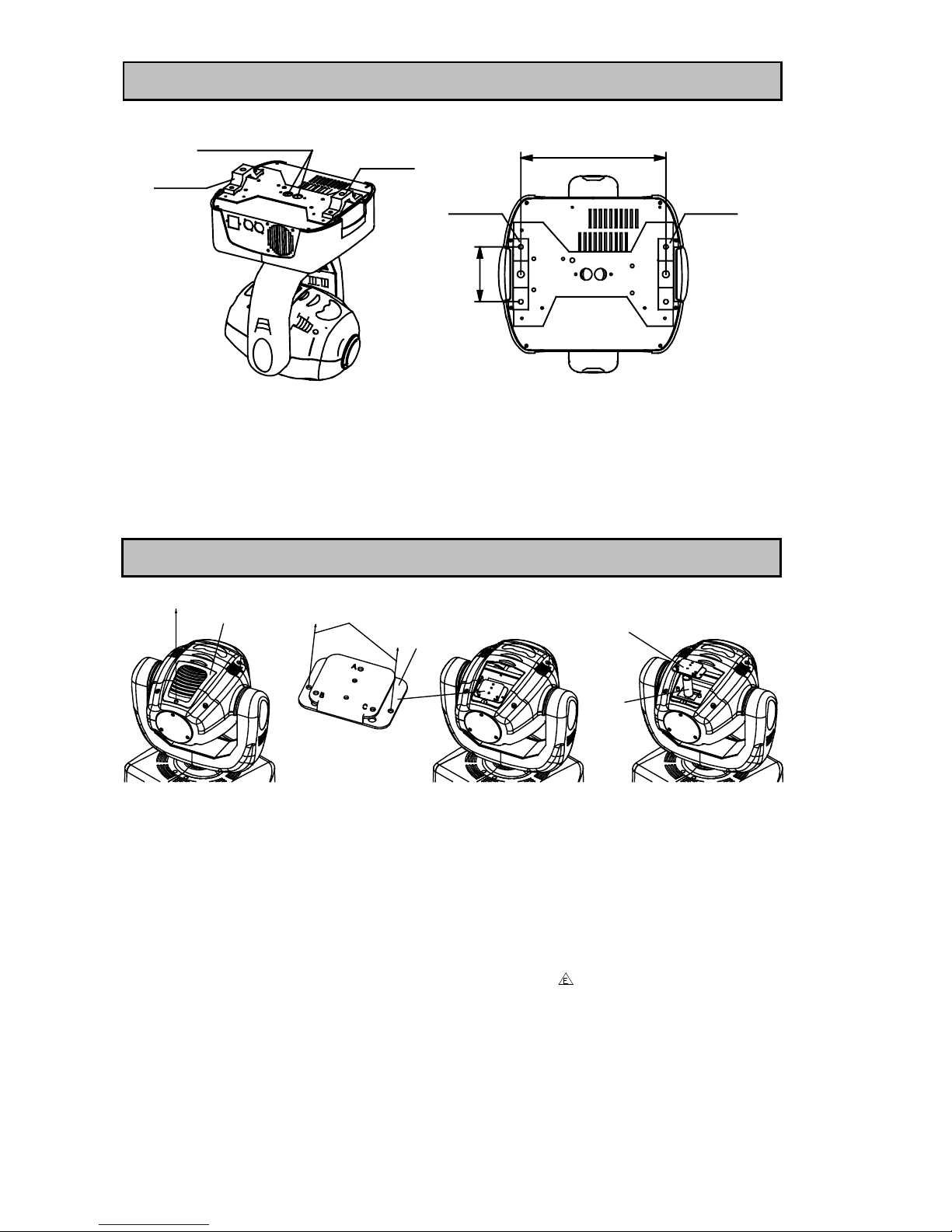
INSTALLING THE PROJECTOR
280mm
BRACKET
106mm
BRACKET
BRACKET
BRACKET
Pass safety fixing
through these holes
The projector should be mounted via its bracket using 2 x M12 bolts. The brackets attach to the
underside of the projector with 4 x M8x25 bolts provided. Always ensure that the projector is firmly
anchored to avoid vibration and slipping whilst functioning. Always ensure that the structure to which
you are attaching the projector is secure and is able to support a weight of 19Kg for each PILOT 250.
For safety the projector should have a secondary fixing with a safety chain through the holes on the
underside of the unit.
WARNING: The projector should NEVER be lifted or carried by the yoke.
FITTING THE LAMP
LAMP ACCESS
HATCH
SCREW
A,B AND C.
LAMP ALIGNMENT SCREWS
LOOSEN THE 2 x M4 SCREWS
LAMP BRACKET
PULL OUT THE LAMP BRACKET
TO ACCESS THE LAMP
LAMP
Undo the screw on the lamp access hatch, and then remove the hatch as shown in the above figure.
Undo the 2 x M4 screws (one on each side of the lamp bracket) and then pull out the lamp bracket
with the old lamp.
Pull out the old lamp and then plug in the new lamp. Do not touch the glass of the lamp with bare
hands.
Replace the lamp bracket and fasten the screws, then replace the lamp access hatch and fasten the
screw.
The MSD series are high pressure lamps with external igniters ( ). Care should always be taken
when handling these lamps. Always read the manufacturers "Instructions for use" enclosed with the
lamp.
PILOT250manualEN.doc
4/16
POWER SUPPLY - MAINS
FUSE F6.3A/250V
FUSE HOLDER
5mm x 20mm
L
E
N
L = BROWN
E = GREEN/YELLOW
N = BLUE
Use the plug provided to connect the mains power to the projector paying attention to the voltage and
frequency marked on the panel of the projector. It is recommended that each projector is supplied
separately so that they may be individually switched on and off.
IMPORTANT
It is essential that each projector is correctly earthed and that electrical installation conforms to all
relevant standards. Power consumption of the PILOT 250 is 410W at 220V.
To change the voltage and/or frequency of the Pilot 250, see the details at the back of this manual.
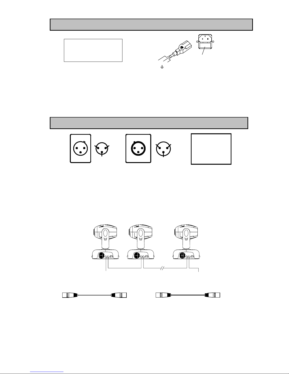
CONTROL CONNECTIONS
DMX IN
1
2
3
1
2
3
DMX OUT
DMX 512
PIN FUNCTION
1
2
3
GND
DATA DATA +
Connection between controller and projector and between one projector and another must be made
with 2 core screened cable, with each core having at least a 0.5mm diameter. Connection to and from
the projector is via cannon 3 pin XLR plugs and sockets which are included with the projector. The
XLR's are connected as shown in the figure above.
Connect the controller’s output to the first fixture’s input, and connect the first fixture’s output to the
second fixture’s input. The rest may be deduced by analogy. Eventually connect the last fixture’s
output to a DMX terminator as shown in the figure below.
Note, care should be taken to ensure that none of the connections touch the body of the plug or each
other. The body of the plug is not connected in any way. The PILOT 250 accepts digital control signals
in standard DMX512 (1990) format.
DMX OUT DMX OUTDMX IN DMX IN DMX OUT
TERMINATORDMX IN FROM
CONTROLLER
No. 1 No. 2 No. n
PILOT 250 uses 3-pin XLR plug / socket. If your controller uses 5-pin XLR plug / socket, you should
convert 5-pin plug / socket into 3-pin socket / plug as shown below.
5 PIN PLUG
Pin 1: GND (Screen)
Pin 2: Signal (data -)
Pin 3: Signal (data +)
Pin 4: N/C
Pin 5: N/C
3 PIN SOCKET
Pin 1: GND (Screen)
Pin 2: Signal (data -)
Pin 3: Signal (data +)
5 PIN SOCKET
Pin 1: GND (Screen)
Pin 2: Signal (data -)
Pin 3: Signal (data +)
Pin 4: N/C
Pin 5: N/C
3 PIN PLUG
Pin 1: GND (Screen)
Pin 2: Signal (data -)
Pin 3: Signal (data +)
When a DMX 512 signal is received the LED located near the digital display will illuminate green.
When not receiving a DMX signal the green and red LEDs will be off, and if the green LED flashes, it
means that the DMX signal is not correct.
PILOT250manualEN.doc
5/16
 Loading...