

Purenex Multipure Aquaversa User Manual

Multi-Pure
®
Multi-Pure Drinking Water Systems
Below the Sink Models
For Model Nos. MP750SB, MP750SI, and MP1200EL
OWNER'S MANUAL
Please retain this manual for future reference.
Multi-Pure Corporation P.O. Box 34630 Las Vegas, NV 89133-4630
Phone (702) 360-8880 Toll-Free (800) 622-9206
www.multipure.com

Multi-Pure Drinking Water Systems
Thank you for selecting a Multi-Pure Drinking Water System to meet your need for quality drinking water. You have
acquired one of the finest drinking water treatment devices available for the reduction of a wide array of contaminants.
We are confident that your Multi-Pure System will make a difference in your life. Thank you for your business.
I. General Information
A Operation & Maintenance Specifications...............................................................................................................3
B. Installation Overview and Part Numbers...............................................................................................................4
C.Warranty.................................................................................................................................................................5
D.Required Tool List..................................................................................................................................................5
II. Installing the Faucet
A. Drilling the Hole.....................................................................................................................................................6
B. Stainless Steel Faucet...........................................................................................................................................7
C.Stainless Steel Faucet with Capacity Monitor......................................................................................................8-9
III. Connecting to your Plumbing.............................................................................................................................10-11
IV. Preparing the Housing
A. Installing the Filter................................................................................................................................................12
B. Attaching the Inlet / Outlet Adapters....................................................................................................................12
V. Connecting the Tubing to your Drinking Water System
A. Blue Faucet Tubing connection to the Outlet Port ..............................................................................................13
B. Clear Tubing connection to the Inlet Port............................................................................................................13
C.Connecting to Ice-Maker, Instant Hot Dispenser or other device (optional) .......................................................14
VI. Placing the Unit Under Your Sink.........................................................................................................................15
VII. Installing the Inline Model.....................................................................................................................................15
VIII. Start-up and Use of Your Drinking Water System..............................................................................................16
IX. Filter Life.................................................................................................................................................................17
X. Product Registration.............................................................................................................................................17
XI. Instructions for Changing Your Filter..................................................................................................................18
XII. Performance Certification.....................................................................................................................................19
XIII. Performance Data Sheet.....................................................................................................................................20-22
XIV. California Certification..........................................................................................................................................23
XV. Troubleshooting....................................................................................................................................................24
XVI. Questions and Answers.......................................................................................................................................25
Table of Contents
F508D/0806
2
MP750Series
Model Num bers MP 750S B, MP 750SI, MP 1200E L*
Approx i m ate Filter Capacit y 750 gallons
Capaci t y with E nd-of-li fe Indicator 1200 gal l ons
Replac em ent F i l t er Type CB6
Approx i m ate Filter Cost $60.00 +
Approx i m ate Flow Rate @ 60 psi 0.75 gpm
Housi ng Compositi on St ai nl ess S teel
Rubber Items Nitri l e (NB R)
Outl et 1/4" tube x 1/ 8" Pipe
Inlet 3/8" tube x 1/ 8" Pipe
Max i m um Worki ng P ressure 100 psi / 7.0 k g/ cm²
Mini m um Worki ng P ressure 30 psi / 2.1 k g/ cm²
Max i m um Operating Temperature 100° F/ 38°C - for col d wat er us e onl y
Mini m um Operating Temperature 32°F/0°C - for c old water use only
Part i cle Retent i on Size sub m i cron (0.5 mi cron)
Certified by: NSF
+ pl us tax and shipping and handli ng
* model c om es with end-of-li fe indicator
NOTES
1. Replacement filters can be purchased directly from Multi-Pure Corporation. The replacement filter model number is CB6.
The approximate retail price of the replacement filter is also shown above. Price excludes sales tax and shipping and
handling fees (prices subject to change without notice).
2. Filter life will vary in proportion to the amount of water used and the level of impurities in the water being processed.
Replace the filter cartridge when the first of the following occurs: (a) annually; (b) when the unit's rated capacity is
reached; (c) the flow rate diminishes; (d) the filter becomes saturated with bad tastes and odors. The rated capacity of the
filter cartridge is 750 gallons for Models MP750SB and MP750SI; capacity of the MP1200EL is 1200 gallons.
3. MP1200EL comes with a capacity monitor that automatically flashes a yellow light when it is time to replace the filter.
4. Not intended to be used where the water is microbiologically unsafe or with water of unknown quality without adequate
disinfection before or after the unit. Systems certified for cyst reduction may be used on disinfected waters that may contain filterable cysts.
5. Do not allow water to freeze in the unit. If unit is exposed to freezing temperatures, drain water from unit and remove filter.
6. Do not allow water to sit in unit for extended periods of time (10 or more days) without being used. If unit is to be left unused
for more than 10 days, drain all water from the system and remove the filter. Upon your return, reconnect the filter in the
housing and continue use. In the event water does sit in the unit for 10 or more days, the system should be flushed by
allowing water to flow to waste for about 3 minutes; then continue use as normal.
7. To dispose of the used filter, remove it from the housing and place the old filter in your normal refuse. The filter disposed of
in a normal landfill will not release any chemical contamination but will probably continue to adsorb additional contaminants
that are disposed of in landfills.
8. Check for compliance with state and local laws and regulations.
3
Operation and Maintenance SpecificationsI.A.
Connect clear tubing to plumbing -- Option A or B
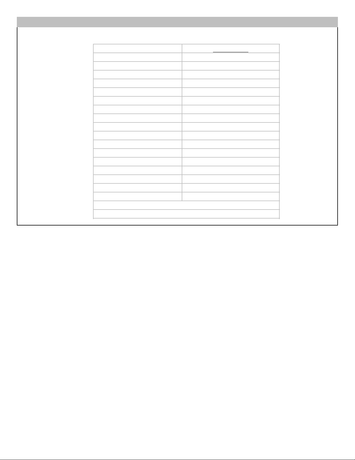
Item # Part # Part Description
1 MC650 Faucet assembly with blue tubing
attached
2 MC232 Clear tubing -connects inlet adapter to
plumbing
3 MC720 Small Outlet adapter - connects to blue
tubing attached to faucet
4 MC730 Large Inlet adapter - connects to clear
tubing
5 MCL500 Housing top
Item # Part # Part Description
6 MC253BS V-band with knob
7 CB6 Carbon Block Filter
8 MC351 O-ring
9 MCB750 Housing bottom
10 MC930ASBL Adapta Valve assembly
11 MC722 Tubing adapter
12 MC252 Black Rubber Cushion
(inside housing top)
13 MC780 Wing nut
14 MC126 Bracket (not shown)
tubing
from faucet
v-band
knob
4
5
9
8
7
6
3
12
13
4
2
cold
cold
sink
sink
riser
Adapta Valve
1/2” configuration
1/2” slip joint nut
No slip joint nut at
angle stop valve
angle stop valve
angle stop valve
Water supply line with
Adapta Valve in 3/8” configuration
Water supply line with
Adapta Valve in 1/2” configuration
A.
B.
riser
1/2” slip joint nut
3/8” slip joint nut
Adapta Valve
3/8” configuration
MP 750SB Installation Overview & Part Numbers
I.B.
OR
2
2
11
11
10
10
1
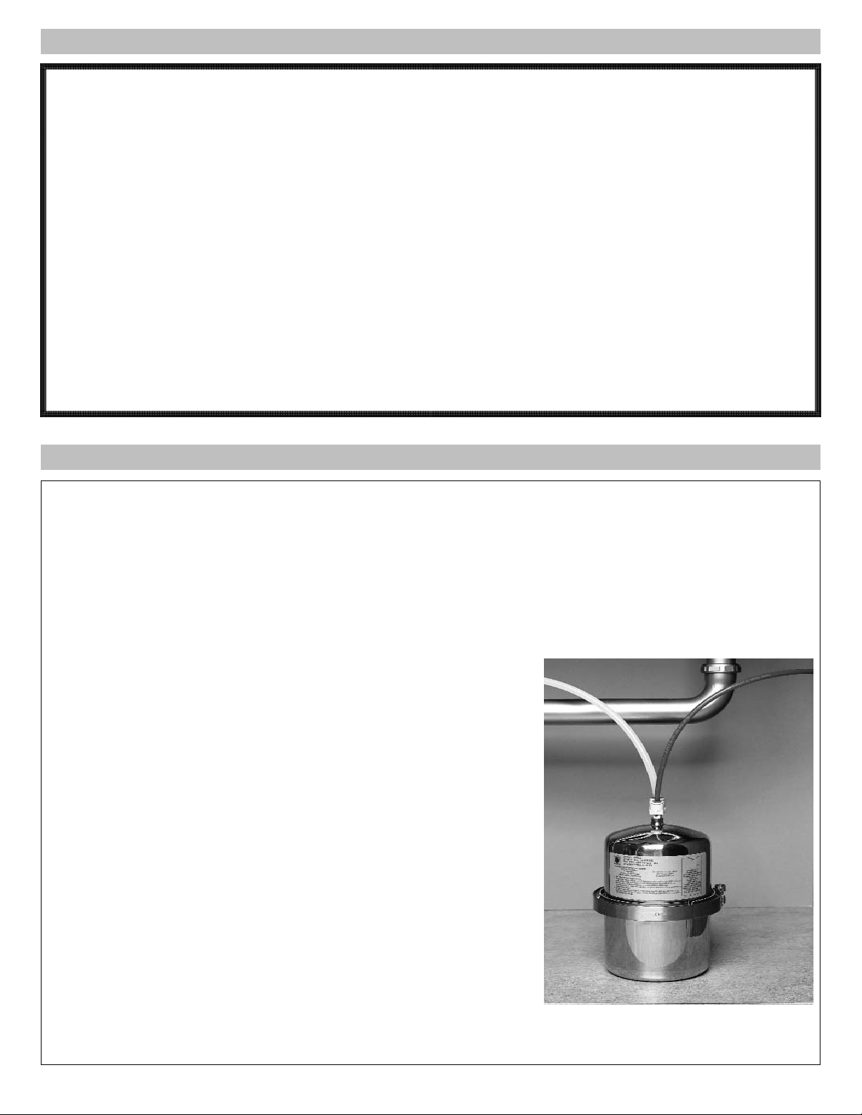
The Models MP750SB, MP750SI, and MP1200EL Drinking Water Systems are designed for use below the sink and can
easily be installed on the incoming cold water line. The MP750SB and MP1200EL units are connected to a specially
designed stainless steel faucet (spigot) which installs directly on your sink, requiring little space. Your below sink unit is
shipped with only one installation kit consisting of the accessories and fittings deemed appropriate for your area. Alternate
accessories may be purchased at a minimal cost.
The Multi-Pure Model MP750SI includes the housing, filter, and adapters; no installation fixtures or accessories are provided. MP750SI is appropriate for an in-line installation and can be used with your existing faucet. It is recommended that
the inline model be installed by a professional plumber in accordance with established plumbing procedures.
Model MP750SB
Required Tool List
The following tools are required to install your below sink Multi-Pure
Drinking Water System:
Installation of Faucet/Spigot (Ceramic/Porcelain Sink):
- 3/8" Reversible Electric Drill
- 7/16" (or 1/2”) high speed steel drill bit
- ½" carbide tipped masonry drill bit
- Hammer
- Center punch
- 8" adjustable wrench
- Pliers or Vise Grips
Installation of Faucet/Spigot (Stainless Steel Sink):
- all of the above (except masonry drill bit), plus…..
- 1/8” high speed drill bit
Adapta Valve Installation:
- 8" adjustable wrench
- Wire Cutter or Knife
Installation of MP1200EL Capacity Monitor:
- (see tool list in Section II.C)
5
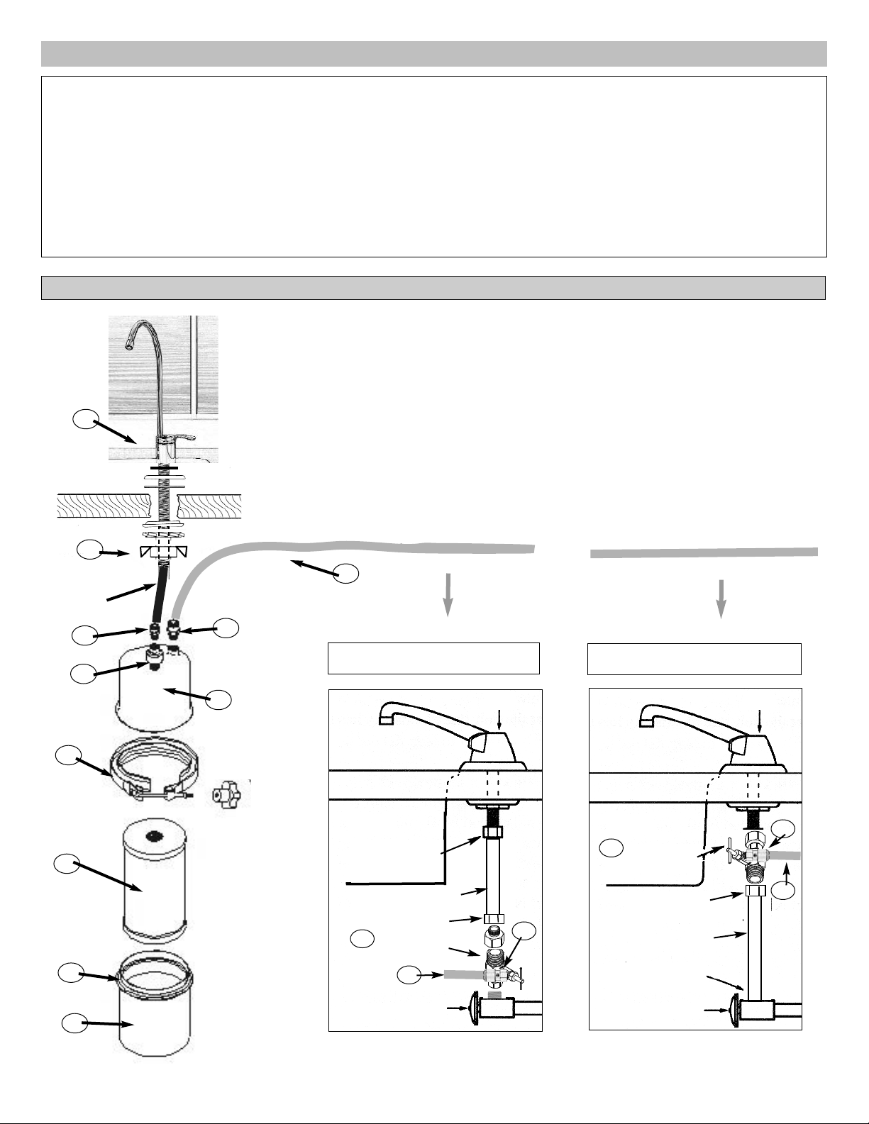
I.D. Below the Sink Installations
Multi-Pure 90-Day Guarantee: Multi-Pure demonstrates its confidence in the performance of its Drinking Water
Systems by offering its 90 day money-back guarantee. If you should find the Drinking Water System unsatisfactory, let
us know within 90 days of purchase, and we will promptly exchange it or refund your money.
Multi-Pure Warranty: Multi-Pure Corporation warrants to the original retail customer its Drinking Water Systems and
components to be free of defects in material and workmanship for use under normal care, and will repair or replace any
System at no charge (excluding transportation to Multi-Pure headquarters) to the customer during the warranty period.
The Drinking Water System housings are warranted for a lifetime (provided that filter has been changed at least once per
year); all exterior hoses and attachments to the System are also warranted for defects in material and workmanship for
one year.
Multi-Pure Solid Carbon Block Filters are warranted for defects in material and workmanship for use under normal care.
The capacity of the filter cartridge depends upon the amount of impurities in the water to be processed. For optimum
performance, it is essential that the Solid Carbon Block Filter cartridge be replaced annually or when it has processed its
listed capacity, whichever comes first.
Except as otherwise expressly provided above, Multi-Pure Corporation makes no warranties, express or implied, arising
by law or otherwise, including without limitation the implied warranties of merchantability and fitness for a particular purpose, to any person. This limited warranty may not be altered, varied or extended except by a written instrument executed by Multi-Pure Corporation. The remedy of repair or replacement as provided under this limited warranty is exclusive.
In no event shall Multi-Pure Corporation be liable for any consequential or incidental damages to any person whether
occasioned by negligence of the manufacturer, including without limitation damages of loss of use, cost of substitution,
property damage, or other monetary loss.
I.C. Warranty
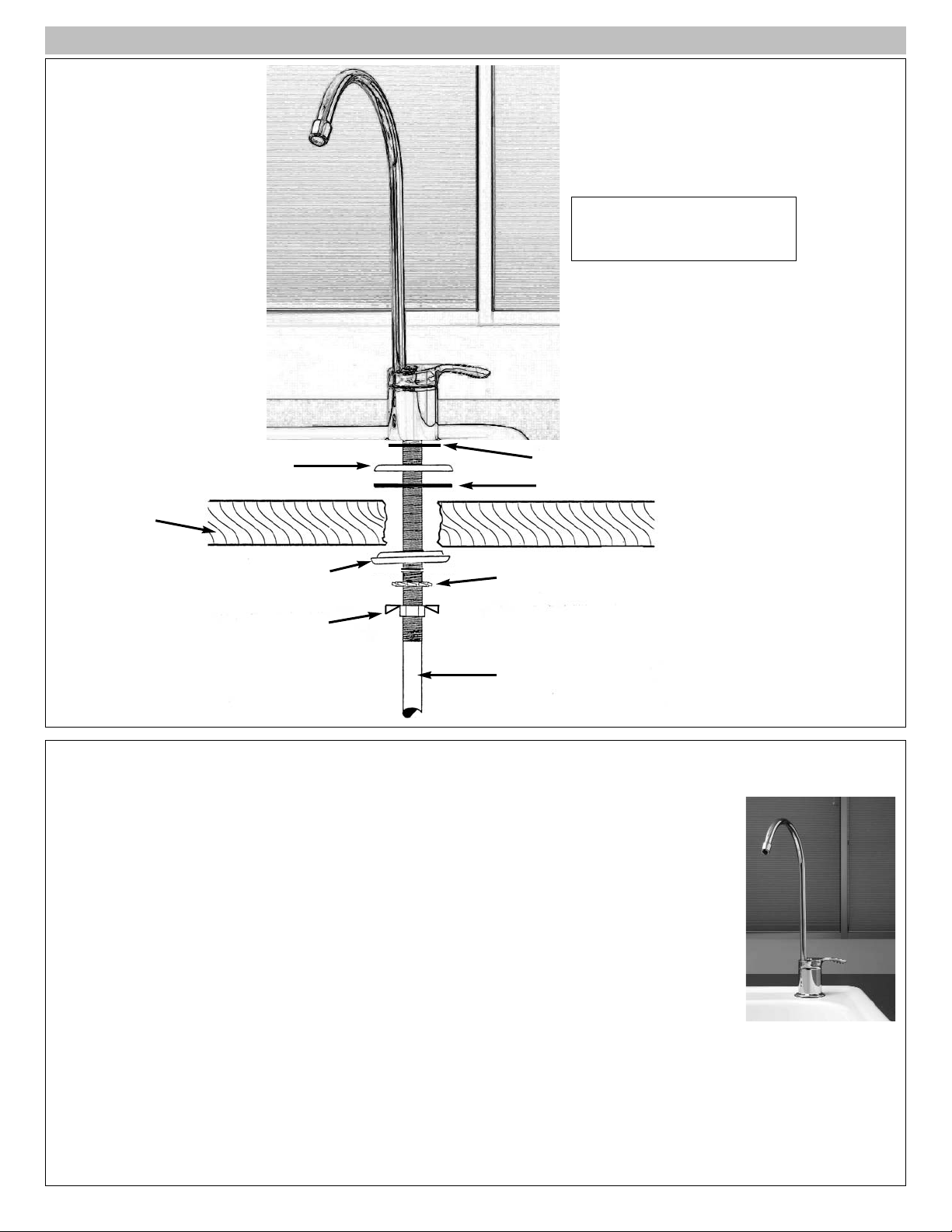
Multi-Pure’s stainless steel faucet can be installed through a standard sink hole, if one
is available. If you have a hole for a side spray hose on your sink, that hole may be
used for your drinking water faucet, eliminating the need to drill a hole for the faucet.
The following instructions are for installing at your sink the special drinking water faucet
included with your below sink model. Determine the type of faucet included with your
unit and review the instructions for installing your type of faucet.
S
t
ainless Steel Faucet: For instructions on installing the Stainless Steel Faucet with
tubing attached that was shipped with Model MP750SB, see Section II.B.
S
tainless Steel Faucet with Cap
acity Monitor: For instructions on installing the
MP1200EL Faucet and Capacity Monitor, see Section II.C.
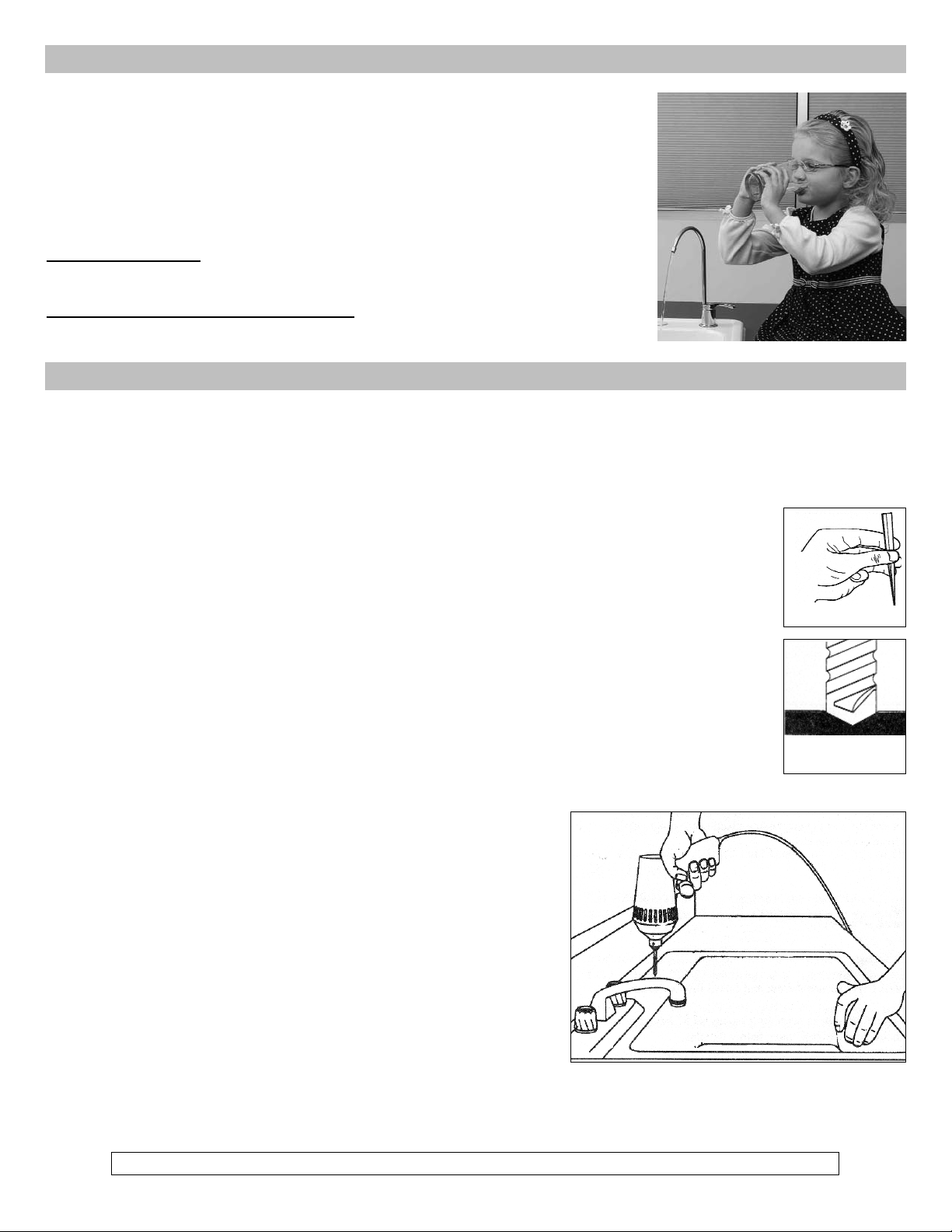
1. Porcelain Sink, Ceramic Sink, or Cast Acrylic Sink
Note: Porcelain, cast acrylic, and ceramic sink surface materials are extremely hard and can crack or chip quite
easily. Use extreme caution when drilling. Multi-Pure Drinking Water Systems accepts no responsibility for consequential damage resulting from the installation of a faucet.
1. Select and mark the spot for mounting the faucet on your sink top.
a. Confirm that there are no reinforcing ribs under the sink location you select for your faucet.
b. If you have an extra hole in your sink for a rinsing hose, you may want to disconnect that hose
and use the existing hole for your drinking water faucet.
2. Using the hammer and center punch, make an indentation by tapping the center punch gently on the
ceramic/porcelain where the hole is to be drilled.
3. Use the ½" carbide tipped masonry drill bit to grind away the porcelain down to the metal, clearing
away enough porcelain to allow for drilling a hole without damaging the porcelain surface.
4. Carefully use the 7/16" ( or 1/2”) high speed steel drill bit (CAUTION: do not allow the 7/16" bit to
"grab" the porcelain - this would damage the porcelain surface) to completely drill a hole through the
metal sink.
2. Stainless Steel or Metal Sink
You will need to use a 1/8" high speed drill bit in addition to the other tools
listed for the installation of a faucet on a stainless steel sink.
1. Select and mark the spot for mounting the faucet on your sink. If you
have an extra hole for a spray hose at your sink, you may want to disconnect that hose and use the existing hole for your drinking water
faucet.
2. Using the hammer and center punch, make an indentation where
the hole is to be drilled.
3. Use the 1/8" high speed steel drill bit to drill a pilot hole.
4. Use the 7/16" (or 1/2”) high speed steel drill bit to completely drill a hole through the stainless steel sink.
Mark the Spot
Carefully grind
away porcelain
6
II. Installing the Faucet
II.A. Drilling the Hole
Note: For drilling a hole in your countertop, please consult with the countertop manufacturer.
7
Mounting the Faucet
1. Note that the blue tubing is attached to the faucet.
2. From the sink / counter top, place over the faucet hole:
a.The larger soft black rubber washer
b. The cover plate
c. The smaller soft black rubber washer
3. From under the sink, slide over the blue tubing:
a. the black plastic (hard) washer (with the small side up)
b. lock washer
c. the wing nut
4. Hand tighten the wing nut to secure the faucet. Using vice grips, secure the wing nut and
faucet below the sink.
5. From above the sink, (CAUTION: protect the faucet base from scratching) using an 8"
adjustable wrench, turn the faucet base clockwise until firm. Then remove the vise grips from
below the sink.
To operate your Multi-Pure faucet, just turn the handle on for continuous flow. To stop flow, return the handle to its
original position.
The faucet is now ready to be connected to your drinking water unit.
See Section V.A.
II.B. Installing the Stainless Steel Faucet
small black washer
large black washer
Cover Plate
Lock Washer
Blue Tubing
Plastic Washer
Wing Nut
COUNTERTOP
Complete Faucet Assembly
with Blue Tubing
MC650
8
II.C. Installing the Faucet with a Capacity Monitor
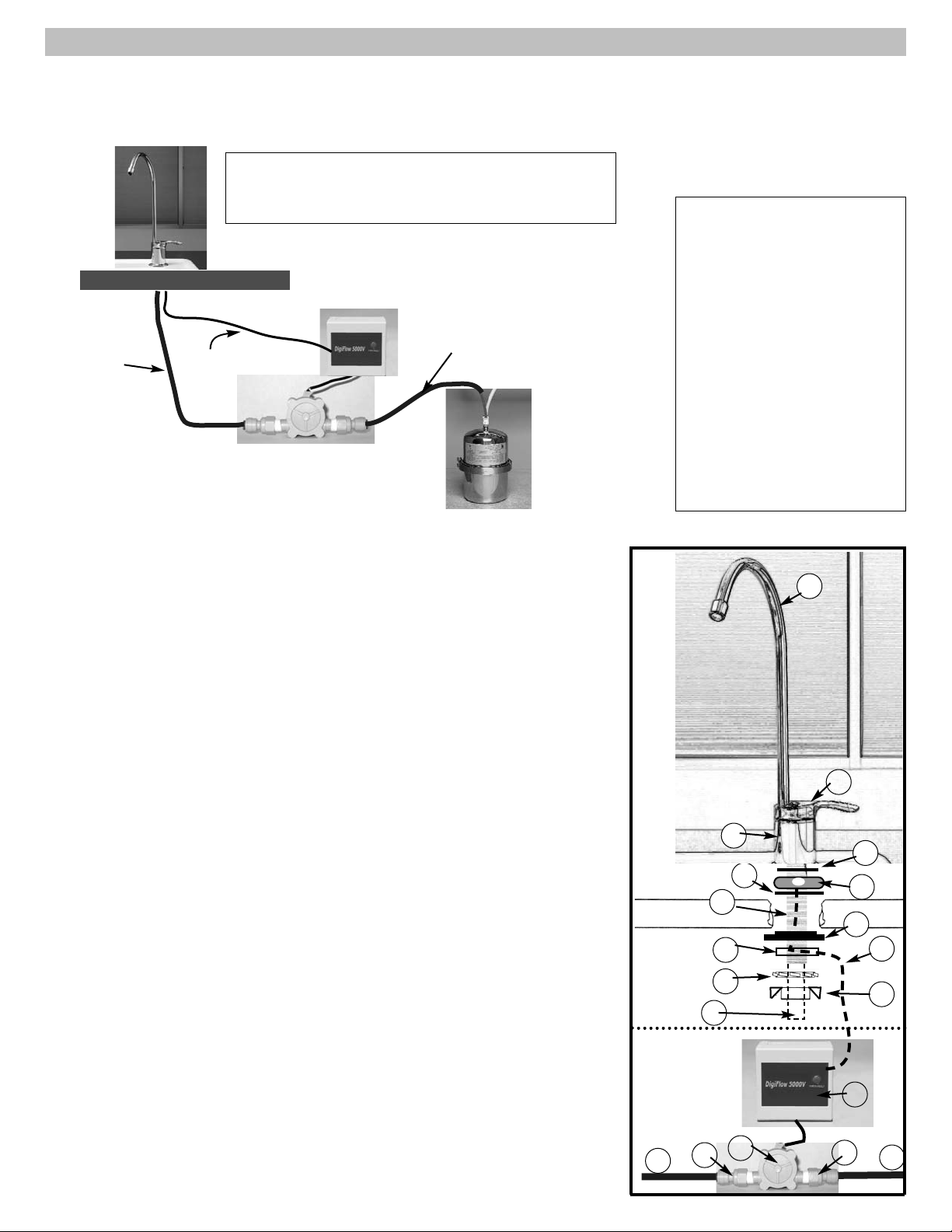
1 spout
2 faucet handle
3 faucet base
4 faucet stud
5 tubing (blue) attached to faucet
6 smaller rubber washer
7 capacity indicator plate (black)
8 black wire
(attached to #7)
9 larger rubber washer
10 hard black washer with side cut
11 track washer
12 lock washer
13 wing nut
14 capacity flow device
15 filter monitor box
16 adapters
(MC745), two
17 tubing from capacity flow device
to housing outlet
Capacity
Monitor
Assembly
Faucets with Capacity
Monitor include:
Mounting the Faucet with a Capacity Monitor:
1. Follow the preceding instructions for drilling the hole; however, use the 1/2”
drill bit all the way through the sink instead of the 7/16” drill bit to allow room to
feed the faucet stud and the monitor cable down through the hole in the sink.
2. Note that the blue tubing is attached to the faucet.
3. From the sink / counter top, place over the faucet hole:
a. The larger soft black rubber washer (#9).
b. Then the Capacity Indicator Plate (#7); feed the attached black cable (#8)
through the hole in the sink / counter. Position the Capacity Indicator Plate
so that the indicator light will be easy to see.
c. Place the smaller soft black rubber washer (#6) over the Capacity Indicator
Plate.
d. Place the faucet base (#3) on the soft washer and Capacity Indicator Plate,
feeding the faucet stud and blue tubing down through the hole in the sink /
counter. The faucet stud will now be accessible from below the sink.
4. From under the sink, do the following:
a. Slide the black plastic hard washer (#10) (with the small side up) over the
blue tubing (#5), black wire (#6) and faucet stud (#4).
b. Slide the black "track" washer (#11) over the threaded faucet stud with
the flat side down. Guide the black wire (#8) through the "track" to assure
that the wire will be protected in the track and not be pinched between the
sink /counter and the stud nut.
c. Slide the lock washer (#12) on the faucet stud.
d. Screw on the stud wing nut (#13), hand-tightening it just enough to keep
the faucet secure on the sink top.
Countertop
tubing from
faucet
tubing from
housing
Filter Monitor Box
Capacity Flow Device
black wire from capacity
indicator plate
Installation Overview
4
5
7
8
9
10
11
12
13
countertop
countertop
1
2
3
6
14
15
5
16
16
17
Your Multi-Pure Drinking Water System is equipped with a DigiFlow 5100V Capacity Monitor that flashes red when the
filter should be changed. Models with capacity monitors are equipped with a chrome-plated designer faucet with the tubing
attached. In addition you will receive the DigiFlow 5100V Capacity Monitor (consists of two pieces), two adapters, and additional tubing (see diagram and parts list below). Not included but required for installation are two AAA batteries.
 Loading...