

Page 1
01. General Provisions
02. Scope of delivery
03. Specifications
04. Driver installation and ventilation
05. Driver features
06. Driver control signal connection
07. Current and voltage selection
08. Driver SSM connection
09. DIP-switch driver tuning
10. PC driver connection via USB interface
11. Driver parameter adjustment by configuration program
12. Driver error and indication
13. Warranty
OPERATIONAL MANUAL
2
3
3
5
6
7
8
9
12
14
16
21
22
PLDS880
Servo-step motor DSP driver
Page 2

www.purelogic.ru8 (800) 555 63 74
01
General Provisions
PLDS880 is a DSP processor based digital driver of Servo-Step
Motor (SSM) with possibility of driver parameter PC adjustment via
USB interface. Driver may work both in servo mode and SM common
driver mode without encoder. In servo mode SSM is controlled as fully
functional servo motor with position and speed control. This allows
obtaining motor maximum moment output and excluding step skip at
overload. Driver is highly efficient, SSM rotation noise and vibration is
significantly reduced.
Device features integral SSM winding SC, encoder power supply SC,
SSM back EMF effect protection circuits; SSM mid-frequency resonance
compensator; power supply voltage polarity reversal protection and
SSM soft start; damper; STEP frequency generator and STEP inlet
frequency excess protection. Driver operates with STEP/DIR/ENABLE
standard protocol. All driver control inlets are optically isolated and
compatible with 2.5V, 3.3V, 5V logic levels. Also module has AUTOSLEEP mode that is started at STEP signal unavailability.
Driver is optimal choice for Purelogic R&D PL57/PL86 Series 2
phase bipolar servo-step motors. Operation with other 2 phase SSM for
instance Leadshine is also possible.
01. General Provisions
!
For more information on using and configuring our products
please visit our site www.purelogic.ru
Page 3

Edition of 09.11.2016
3
PLDS880. Servo-step motor DSP driver
Specifications
Scope of Delivery
• PLDS880 step motor DSP driver - 1 piece
• Operational Manual - 1 piece
03
02
SSM step division (micro step)
Integral generator SSM speed
ERROR output parameters
Module net weight
STEP signal max. frequency
Module power supply voltage
SSM operating current
SSM max. speed
SB encoder support
Insulation resistance
Operating temperature
Diff.inlet, 500-1024 pulse/rev
500 MOhm
0...50 °С
1...512
0…500 rev/min
50V/50mA MAX
0.45 kg
200 kHz
18…80V (typical value 70V)
2А…10А
3000 rev/min
• All driver connections and operation mode changes shall be made
only with disabled power supply source
• Do not install power supply disconnector (circuit breaker) after
power supply source (at driver power supply line). Disconnector may be
installed only at ~220V side power supply unit inlet.
• Do not connect driver power supply in series. Only “star” type
connection is allowed (each driver separate power supply line is
connected to PSU).
Page 4
www.purelogic.ru8 (800) 555 63 74
03. Specifications
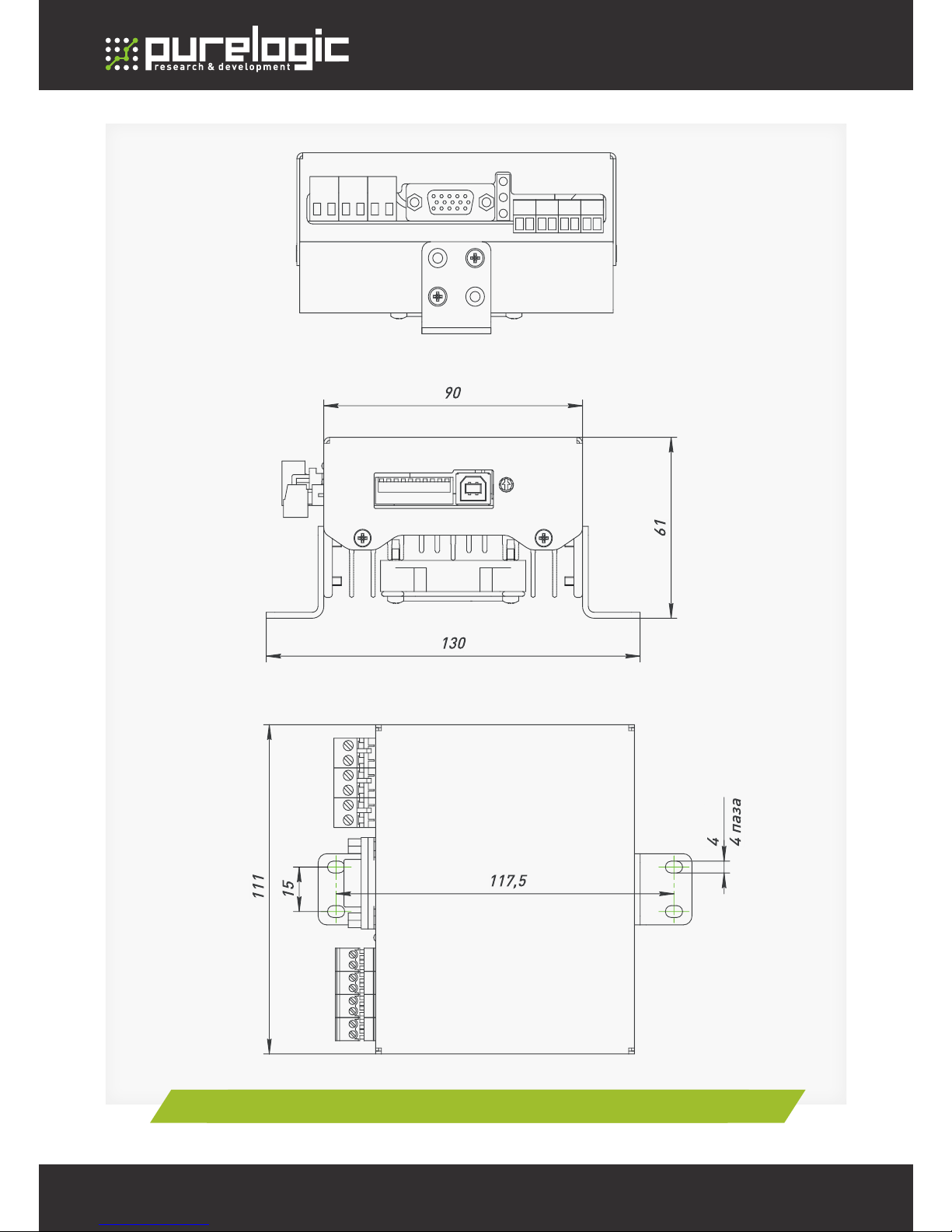
Figure 1. PLDS880 SSM driver dimensions
Page 5
Edition of 09.11.2016
5
PLDS880. Servo-step motor DSP driver
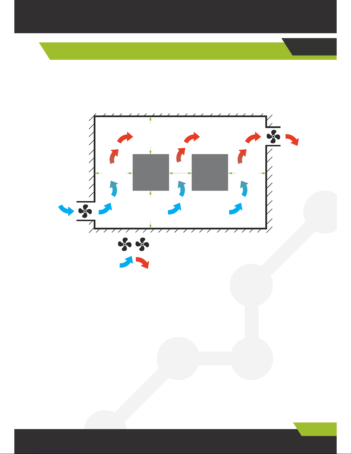
To ensure optimal thermal conditions equipment inside NC control rack
shall be mounted according to diagram below:
Драйвер –Driver
Вентиляторы - Fans
Направление воздушного потока - Air stream direction
Ambient conditions
1) Operating temperature: 0-450C.
2) Ambient operating humidity: below 40-80% (w/o condensation).
3) Storage temperature: -40 ~ 550C.
4) Storage ambient humidity: below 80% (w/o condensation)
5) vibration below 0.5G.
6) avoid moisture entry
7) avoid direct sunlight
Driver Installation and Ventilation
04
>100mm >100mm
>100mm
>25mm
— Направление воздушного потока
Драйвер Драйвер
>100mm
— Вентиляторы
Page 6

www.purelogic.ru8 (800) 555 63 74
04. Driver Features
05
Driver Features
• Driver PC adjustment via USB interface. USB interface is galvanic
isolated from driver.
• Driver may work in both servo mode and SM conventional driver mode
without encoder
• Any SSM step division within 1…512.
• Pulse number per (PPR, CPR) encoder revolution is 500…1024.
• PI-regulator in SSM phase control current loop.
• STEP/DIR/EANBLE/ERROR module control signal optic isolation.
• Integral STEP signal test generator (0…500 rev/min).
• SSM soft start. After energizing or ENABLE signal SSM winding
current is increased gradually. This excludes typical “impact” at SSM
start.
• AUTO-SLEEP mode, driver after 1 sec. of downtime (STEP signal
unavailability) automatically switches to SSM rotor complete/partial
current hold mode to reduce SSM heating.
• SSM winding SC, SSM misconnection module protection
• Encoder power supply circuit SC module protection
• Power supply voltage polarity reversal protection (Driver start is
failed)
• SSM reverse EMF effect protection
• Heating protection (temperature sensor)
• Integral SSM mid-frequency resonance compensator.
• Integral damper
• ERROR driver trouble signal opto-isolated output
• SSM connection easy-to-use dismountable terminals/
• STEP frequency, emergency, driver power supply indication.
8) avoid oil mist and salt entry
9) avoid corrosive liquefied gas entry
Page 7
Edition of 09.11.2016
7
PLDS880. Servo-step motor DSP driver
Module is controlled by standard STEP/DIR and ENABLE signals.
Signals are transmitted at differential opto-isolated inlets.
Yellow LED is illuminated and driver is ON at generated ENABLE
signal. Yellow LED is flashing and SSM is rotating at produced STEP
frequency.
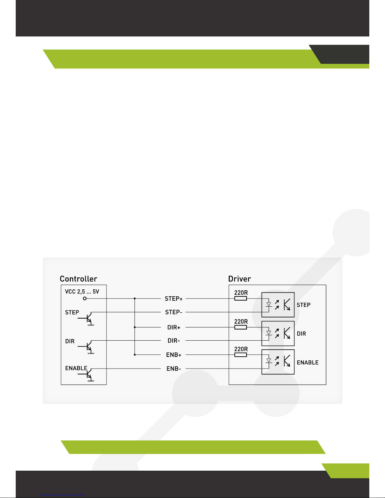
Configuration of control differential inlets and connection to control
system (controller) with “open collector” type outlets are shown at
Figure 2. Module control signals are connected in accordance with (Fig.
5).
STEP signal parameters: Operating voltage 2.5V, 3.3V. 5V (connection
of additional current limiting resistor may be required).
Control Signal Connection
06
Figure 2. Configuration of differential inlets
Page 8

www.purelogic.ru8 (800) 555 63 74
07. Curret and voltage selection
07
Current and voltage selection
Driver power supply max. voltage selection depend upon used SSM
and its required speed. This SSM optimal power supply voltage is
calculated by formula U= √ 32* (SSM phase inductance in mH) but
max. 80V. PL57 type SSM recommended voltage is 45V. PL86 type SSM
recommended voltage is 70V.
Power supply current shall be selected considering 50…70%
of SSM winding specified operating current. SSM operating current is
set by corresponding value in configuration program (Work_Current_
Min and Work_Current_Max). If no STEP signal is available more than
1 second driver is switched to sleep mode (AUTO-SLEEP mode) and
reduces winding current.
max. 20 mA current consumption, signal 2 ms min. time. SSM step is
performed at signal rising edge.
DIR signal parameters: Operating voltage 2.5V, 3.3V. 5V (connection
of additional current limiting resistor may be required), max. 20 mA
current consumption, 200 ns actuation time before/after STEP rising
edge.
ENABLE signal parameters: Operating voltage 2.5V, 3.3V. 5V
(connection of additional current limiting resistor may be required),
max. 20 mA current consumption, 100 ms actuation time. Logical unit
(inlet is energized) is SSM driver is ON and SSM windings are deenergized, zero (nothing is generated or 0V at inlet) is SSM driver is ON
and SSM windings are energized.
Page 9

Edition of 09.11.2016
9
PLDS880. Servo-step motor DSP driver
PLDS880 perfectly fits for controlling of Purelogic R&D PL57/PL86
Series bi-polar and unipolar step motors.
Purelogic R&D SSM is connected to driver according to Fig. 3
(terminals PH1.1(+A), PH1.2(-A) and PH2.1(+B), PH2.2(-B) and encoder
connector). Encoder connector contact designation is also shown at Fig.
3. PLDS880 driver is connected acc. Fig. 4.
Driver is protected against SSM winding misconnection
between each other/to “+” of power supply and Short Circuit in encoder
power supply circuit. Note that motor reverse rotation is started at
reversal of SSM PH1.x<>PH2.x phase connection and encoder A<>B
signals (analog of DIR signal inversion).
Connection of SSM phases and encoder signals is
interrelated. If driver generates error 50 (OverPosition) at initial startup exchange SSM PH1.x<>PH2 phases without changing of encoder
signal connection.
Driver SSM conductor length shall be max. 10 meters.
Longer conductors may result in driver operation failures.
It is highly recommended to arrange SSM wires in phase
bundles: power +A and –A, +B and –B, encoder outlet A and A, B and
B, put bundles in screened metal braids (power wires in one braid,
encoder signal wires to other braid). SSM casing and braids shall be
earthed. Do not arrange and lay encoder signal wires and SSM power
conductor in one braid
Driver MMC connection
08
Page 10

www.purelogic.ru8 (800) 555 63 74
08. Driver SSM connection
Блок питания – Power Supply Unit
Шаговый двигатель – Step motor
Устройство коммутации – Switching device
Page 11

Edition of 09.11.2016
11
PLDS880. Servo-step motor DSP driver
Fig. 3 Driver connection general arrangement drawing
Page 12

www.purelogic.ru8 (800) 555 63 74
08. Driver SSM connection
Fig. 4 Driver motor connection
разъем DHS15F
на кабеле DHS15F-3м
и на драйвере PLDS880
разъем DHS15M
на шаговом двигателе
Разъем
Энкодер Контакт Название
Выход энкодера
И на драйвере
Красный Зеленый Желтый
Синий Черный Белый
Разъем на шаговом двигателе
На кабеле
Цвет Назначение
At cable
Colour Designation
Connector
Encoder Contact Description
Encoder outlet
And at driver
Red Green Yellow
Blue Black White
Connector at step motor
Page 13

Edition of 09.11.2016
13
PLDS880. Servo-step motor DSP driver
Driver operating parameters (step division, Autosleep mode ON/OFF,
integral STEP generator ON/OFF, SSM downloaded profile selection)
may be set by SW1…SW10 switches. All switchings shall be performed
when driver power supply is ON.
Standard profile (certain type SSM parameter set) is selected with
SW1, SW2, SW3 switches according to Figure 5.
At power supply driver automatically downloads profile set by
SW1, SW2, SW3 switches from non-volatile memory “Bank 0” value
downloads profile saved in “0” memory. SSM step division is specified
with SW4, SW5, SW6, SW7 switches according to Figure 6. Autosleep
mode is controlled with SW8 switch. If it is in lower position (ON
position) mode Autosleep is enabled. If it is in upper position Autosleep
is disabled. PLDS880 driver operation mode is selected with SW9 and
SW10 switches.
At started STEP signal internal generator SSM speed and
direction may be controlled by potentiometer STEP GENERATOR. At
potentiometer handle left or right movement from center position SSM
rotor shall rotate clockwise or counter clockwise correspondingly.
SSM rotor speed depends upon inclination of potentiometer handle
from center position.
Fig. 5 Driver standard profile selection diagram
Земля не используется
Напряжение питания
Power supply voltage
Ground Spare
DIP-switch driver adjustment
09
Page 14

www.purelogic.ru8 (800) 555 63 74
10. PC driver connection via USB interface
10
Driver PC connection via USB
PLDS880 driver may be connected to PC via galvanic isolated USB port
for parameter adjustment.
For PLDS880 module PC correct operation configuration
program shall be downloaded and virtual COM-port driver shall be
installed using link: http://www.purelogic.ru/files/downloads/SOFT/
PLDxxx_SW.zip
Module PC connection procedure
• Connect PLDS880 to PC using A/B type USB cable;
• Switch on PLDS880 driver;
• Start configuration program;
• In configuration program pop-up window specify COM-port
assigned to PLDS880 driver. Port number may be found by pressing
WIN+PAUSE in Device Manager, in Port (COM and LPT) group (Fig. 8).
Then press Connect button (Fig. 9)
Fig. 7 Driver operation mode selection diagram
Fig. 6. SM and SSM step division selection diagram
Page 15

Edition of 09.11.2016
15
PLDS880. Servo-step motor DSP driver
Fig.8 Virtual COM-port in Device Manager
Панель управления – Домашняя страница
Панель управления – Домашняя страница
Диспетчер устройств
Файл Действие Вид Справка
Настройка удаленного доступа
IDE ATA/ATAPI контроллеры
Защита системы
Видеоадаптеры
Звуковые, видео и игровые устройства
Диспетчер устройств
Дисковые устройства
Клавиатуры
Control panel –Homepage
Control panel –Homepage
Device manager
File Action View Help
Remote access adjustment
Controllers IDE ATA/ATAPI
System additional parameters
Video adapters
Audio, video and game devices
Device manager
Disk devices
Keyboards
Page 16

www.purelogic.ru8 (800) 555 63 74
10. PC driver connection via USB interface
Fig. 9 Device connection via virtual COM-port
Компьютер
Последовательный порт (СОМ1)
Контроллеры USB
Процессоры
Мониторы
Сетевые адаптеры
Мыши и иные указывающие устройства
Системные устройства
Центр поддержки
Порты (COM и LPT)
Устройства HID (Human Interface Devices)
Центр обновления Windows
Computer
Serial port (СОМ1)
USB controllers
Processors
Monitors
Network adapters
Mouse and other indicating devices
System devices
Support Center
Ports (COM and LPT)
HID (Human Interface Devices) devices
Window Update
Счетчики и средства производительности Performance Information and Tools
Page 17

Edition of 09.11.2016
17
PLDS880. Servo-step motor DSP driver
If COM-port is selected correctly and PLDS880 is ON driver
parameters are displayed in program main window (Fig.10). “Status:
OK” will be in status line.
Fig. 10 Program main window
11
Driver parameter adjustment in configuration program
SSM standard profiles prepared by Purelogic R&D are recommended
and driver parameters shall be adjusted only in exceptional cases.
Each profile comprises set of parameters displayed in configuration
program window. All parameters are divided to adjustable (changeable)
and displayed (not changeable) ones.
Using configuration program Customer is able to:
• Change profile parameters. After any parameter change press
“Apply” button
Page 18

www.purelogic.ru8 (800) 555 63 74
11. Driver parameter adjustment by configuration program
• Save/Download profile (current parameters) to/from driver non-
volatile memory. 7 memory banks “0”….”6” are available.
• Save/Download profile (current parameters) to/from file.
• Download standard profiles from non-volatile memory.
Standard profiles are developed by Purelogic R&D specialists for
certain type SSM.
If Customer changes profile and wishes driver to operate with it
at every start then it is required to save profile in driver non-volatile
memory bank “0” and set profile downloading from “Bank 0” by SW1,
SW2, SW3 switches. Otherwise profile may be saved in “1”…”6” or to file
for following future use.
If Customer changes profile without it saving then modified profile
will be deleted from memory after de-energizing and driver will
download profile set by SW1, SW2, SW3 (Fig.5) after energizing.
Description of driver control program menu items:
• “Connect/Disconnect” is driver connection setup.
• “Apply” is button that shall be pressed after any profile parameter
change. Parameter is modified physically in driver RAM according
values set in program corresponding fields.
Hot key is ENTER.
• “Save →write profile in memory” is saving of current profile
(parameters) in any of 7 available banks of non-volatile memory. “0”
bank is working “Bank 0” and “1”…”6” banks are additional.
• “Save → write profile in file” is saving of current profile
(parameters) to file. This is very useful for quick adjustment of other
drivers with the same parameters.
• “Download→ Download standard profile is downloading of standard
profiles (according to step motor name)
to driver RAM. Enables driver quick adjustment for SSM certain
model.
• “Download → Download profile from memory” is profile
downloading from 7 available banks of non-volatile memory to driver
RAM. Enables quick downloading previously saved profiles.
• “Download → Download profile from file” is profile downloading
from file to driver RAM. Enables downloading of previously saved profile
from file.
Page 19

Edition of 09.11.2016
19
PLDS880. Servo-step motor DSP driver
• “Settings → Information” is description of configuration program
operation, driver parameters.
• “Settings → Language” is selection of configuration program
interface language.
Description of adjustable parameters:
• “Work_Current_Max” is maximum operating current of step motor
phases, peak current. Current is increased to this value automatically
at overloading. Range is 0.2 – 1.0 (corresponds to 2A-10A).
• “Work_Current_Min” is nominal operating current of step
motor phases specified in SM technical certificate. Range is 0.2-0.8
(corresponds to 2A-8A).
• “PI_I_Kp” is PI regulator proportional gain in step motor phase
current regulating loop. Range is 1.0-4.0. Impacts SM acceleration, LF
resonance.
• “PI_I_Ki” is PI regulator integral gain in step motor phase current
regulating loop. Range is 0.0-1.0. Impacts SM acceleration, LF
resonance.
• “PI_M_Kp” is PI regulator proportional gain in frequency multiplier
loop. Range is 0.1-4.0. Value PI_M_Kp <1 permits to smooth STEP
command impulse irregularities. Value PI_M_Kp>1 permits to react
more strongly on STEP command input impulse change.
• “PI_M_Ki” is PI regulator integral gain in frequency multiplier loop.
Range is 0.0-1.0.
• “PI_POS_Kp” is PI regulator proportional gain in position
regulating loop. Range is 0.1-4.0. The higher is PI_POS_Kp the faster
SM rotor is placed in set position.
• “PI_POS_Ki” is PI regulator integral gain in position regulating
loop. Range is 0.0-1.0. Value PI_POS_Ki >0 makes lag effect at SM rotor
placement in set position.
• “PI_SPEED_Kp” is PI regulator proportional gain in speed
regulating loop. Range is 0.1-4.0. The higher PI_SPEED_Kp value is the
higher is SM winding current reaction to STEP command speed change.
• “PI_SPEED_Ki” is PI regulator integral gain in speed regulating
loop. Range is 0.0-1.0. PI_SPEED_Ki > 0 value makes lag effect at SM
winding current reaction at STEP command speed change.
• “Elec_Damp_K” is step motor damping rate (resonance
Page 20

www.purelogic.ru8 (800) 555 63 74
12 Driver error and indication
suppression). Range is 0.0-4.0 (0.0 is damping OFF, 4.0 is maximum
damping).
• “Elec_Damp_Lim” is step motor damping limit. Range is 0.0-1.0.
• “Driver_En” is parameter controlling driver ON/OFF. “1” is driver
ON. “0” is driver OFF.
• “Driver_ID” is driver identification which is assigned by User. Range
is 0 – 10000.
• “El_Damp_En” is parameter controlling resonance suppression
circuit ON/OFF. “1” is ON, “0” is OFF.
• “Auto_Sleep_En” is parameter controlling step motor current
reduction circuit ON/OFF at down time. “1” is ON. “0” is OFF.
• “Control_Type” is parameter selecting step motor control mode:
0 is SERVO mode STEP/DIR/ENABLE;
1 is SERVO with potentiometer R and DIR/ENABLE signals;
2 is STEP/DIR/ENABLE normal mode w/o feedback;
3 is normal mode with potentiometer R & DIR/ENABLE signals and
w/o feedback.
• “Microstep_Sel” is step motor step division ratio. Range is 1-512.
• “QEP_PPR” is Encoder resolution in pulse per CPR, PPR revolution.
Range is 500-1024.
PI_Pos_Kp, PI_Pos_Ki, PI_SPEED_Kp, PI_SPEED_Ki, QEP_PPR
parameters are not used in operational modes w/o encoder.
Description of displayed parameters
Actual parameters are parameters that User is not able to change
from configuration program but they may be changed in process of
device operation.
Actual parameters include:
• “Motor_Speed” is actual step motor rotor speed. Range is 0.0-1.0
(corresponds to 0-3000 rev/min).
• “Error_Code” is driver disabling error code. See below.
• “Bus_Volt” is actual power supply voltage in volts (V).
• “Temp_Core” is DSP processor actual temperature. It is measured
in Celsius degrees (0C). Temperature sensor is installed in DSP
processor.
• “Temp_Heatsink” is radiator actual temperature. It is measured in
Celsius degrees (0C). Temperature sensor is installed at radiator.
• “FLAG_STEP” is STEP optical inlet actual status. “1” is STEP
Page 21

Edition of 09.11.2016
21
PLDS880. Servo-step motor DSP driver
command signal frequency ON. “0” is STEP command signal frequency
OFF.
• “FLAG_DIR” is DIR optical inlet status. “1” is step motor shaft
clockwise rotation. “0” is counter clockwise rotation.
• “FLAG_ENB” is driver actual status ON/OFF. “1” is ON, “0” is OFF.
It depends upon Driver_En parameter and ENABLE optical input status.
In process of operation device tracks several internal parameters.
If value of any parameter exceeds threshold value the driver shall be
disabled. Red LED is lighted, yellow LED is gone out and “Error_Code”
parameter in configuration program will have error code.
Driver errors, “Error_Code” parameter:
0 is OK, normal operation
10 is UnderVoltage, power supply voltage < 15V. 11 is OverVoltage
SW, step motor phase voltage > 85V (including due to reverse EMF that
damper is not able to suppress).
12 is OverVoltage HW, step motor phase voltage > 85V (including due
to reverse EMF that damper is not able to suppress).
20 is OverCurrent SW, current overload.
21 is OverCurrent HW, current overload.
30 is OverTemp1, DSP controller overheating.
31 is OverTemp2, power key, radiator overheating.
40 is OverRPM, step motor shaft speed > 3000 rev/min.
41 is OverFreq, STEP command signal input frequency > 200 kHz.
42 is OverSpeed, speed regulating loop overload.
50 is OverPosition, position regulating loop overload.
Indication:
Green LED is ON, power supply voltage is applied. If it is OFF, power
supply voltage is not applied.
Red LED is ON, driver is OFF, emergency. If this LED is OFF then
driver is ON, no emergency.
Yellow LED is ON, ENABLE signal is generated and driver is ON. If
this LED is OFF, then there is no ENABLE signal and driver is OFF.
Driver errors and indication
12
Page 22

www.purelogic.ru8 (800) 555 63 74
13. Warranty
Guaranteed service life is 12 months from purchase date. Guarantee
is valid only in case of observance of operational and preventive
maintenance conditions.
1. General provisions
1.1. If Goods are purchased as components Seller guarantees
operability of each component but is not responsible for quality of their
joint operation (improper selection of components).
If you have any questions, contact our technical specialists for
technical assistance.
1.2. Seller is not guarantee compatibility of purchased Goods with
Buyer components or Goods purchased from the third parties.
1.3. Article parameters and scope of delivery are subject to change
by Manufacturer without notice due to constant technical improvement
of products.
2. Guarantee service acceptance criteria
2.1. Goods are accepted for guarantee service in the same
configuration as they have been purchased.
3. Guarantee service procedure
3.1. Guarantee service is provided by testing (checking) of Goods
declared defects.
3.2. Guarantee repair is performed after defect confirmation.
4. Guarantee does not cover glass, electric lamps, starters and
consumables and also:
Or driver failure. If this LED is flashing then STEP frequency is
generated and SSM is rotating.
At power supply green and red LEDs are ON. In 1 sec in case
failure unavailability red LED is OFF and yellow LED is set lighting
according to STEP/ENABLE signals.
13
Warranty
Page 23

Edition of 09.11.2016
23
PLDS880. Servo-step motor DSP driver
This article is made and accepted in accordance with mandatory
requirements of effective technical documentation and considered as
suitable for operation
Batch No: QCD:
4.1. Goods with damages due to improper transportation and storage
conditions, misconnection, off-design operation or conditions that
are not specified by Manufacturer (including excess temperature and
humidity), damages due other conditions (power supply voltage surges,
natural disasters etc) and having mechanical and thermal damages.
4.2. Goods with effects of impact and/or entry of foreign matters,
objects (including dust), liquids, insects and having foreign signs.
4.3. Goods with signs of unauthorized access and/or repair (signs of
opening, crude soldering, element replacement etc.)
4.4. Goods with self-diagnostics indicating improper operation
conditions.
4.5. Technically complex Goods which erection, assembling and
commissioning works are performed by other specialists but not
specialists of Seller or companies recommended by Seller except cases
directly specified by Goods documentation.
4.6. Goods that operation is performed under conditions when
electric power supply does not correspond to Manufacturer
requirements and in absence of equipment and network electric
protection devices.
4.7. Goods that have been resold by initial Purchaser to the third
persons.
4.8. Goods with defects occurred as result of use of poor quality or
exhausted spare parts, consumables, accessories and in case of use of
spare parts, consumables, accessories that are not recommended by
Manufacturer.
Page 24

Please note that this documentation is subject to change
due to the continuous technical
improvement of our products. You can always download
the latest version on our website www.purelogic.ru
www.purelogic.ru
Contact information
+7 (495) 505-63-74 - Moscow
+7 (473) 204-51-56 - Voronezh
394033, Russia, city of Voronezh.
Lenin Av., 160
Office 149
Mon-Thu: 8.00–17:00
Fridey: 8.00–16.00
Time-out: 12.30–13.30
sales@purelogic.ru
 Loading...