

User manual
PLCM-R1
CNC machine Ethernet control panel

CONTENTS:
1. Outline
1
2. Delivery set
3. Specifications
4. Main controls
5. Setting of control panel for operation with MACH3 program
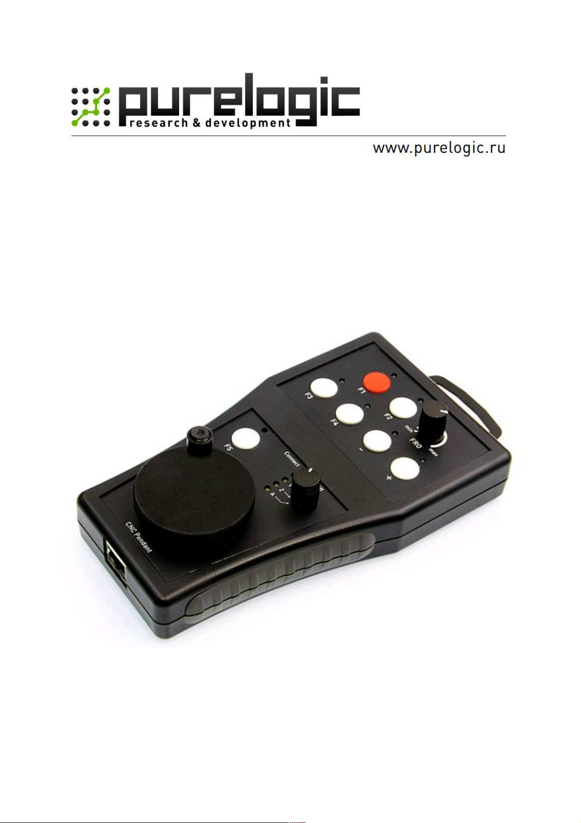
1. OUTLINE
Control panel is used for remote control of CNC machine. Control panel is compatible with MACH3 program; it is
connected to PC via Ethernet interface. Operation panel has flexible settings – all control keys and LED indications are
programmed by user. Operator of CNC machine can precisely position cutting tool, change cutting conditions and
execute programmed commands using control panel.
Control panel is powered from USB bus. Voltage is supplied to panel via free conductors of Ethernet cable. Supply
voltage is injected into Ethernet cable by means of special adapter (supplied in delivery set).
Control panel has 7 control buttons and 7 general purpose LED indicators, movement axis selection switch, encoder
and potentiometer for smooth parameter changing (for example, NC program execution speed, etc.).
2. DELIVERY SET
1
1
2
3
• PLCM-R1 CNC machine control panel – 1 piece
• PLCM-R1 connection and setting manual – 1 piece
• Software disc – 1 piece
• Ethernet cable – 2 pcs.
• B type USB cable – 1 piece
• Power injector – 1 piece
• Fixing pawl – 1 piece
3. SPECIFICATIONS
Supply voltage
Max. current consumption 250mA
Control interface
Number of control buttons 7
Number of LED indicators
Additional controls
Insulation resistance 500mOhm
Operating temperature 0 ... 50 °С
Weight without package 0.3 kg
Dimensions (WxHxD) 80 х 20 х 55 mm
Ethernet, RJ-45 connector
Compatible with MACH3 program.
7 programmable indicators
4 indicators of axis selection
5V DC
via USB bus of PC
Encoder
Potentiometer
Current axis switch
-1-
4. MAIN CONTROLS
USE HIGH-GRADE JAM-PROOF Ethernet CABLE (cat. 5 or higher). CONTROLLER IS COMPATIBLE WITH
MACH3 R3.043.xxx VERSIONS OR LATER.
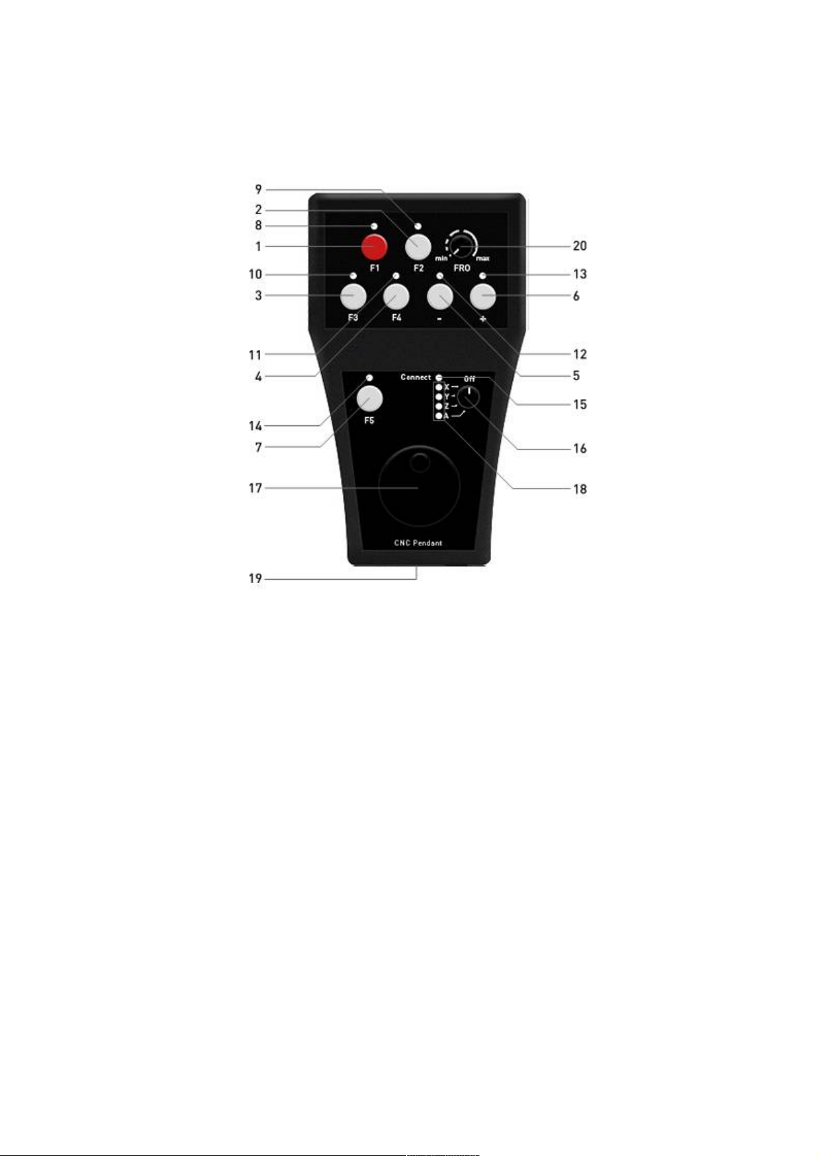
Fig. 1. Layout of buttons and indicators
• 1..7 buttons do not have specific designation, they can be programmed to any function. If control panel with
MACH3 software is used, any code can be assigned to each button (list of user interface buttons, OEM Buttons).
• Similarly, 8..14 Led indicators can be used for any purpose. Specifically, any indication can be assigned to each
LED indicator (OEM LEDs).
• LED 15 is lit when connection with control software is established.
• Switch 16 is used for selection of axis to be controlled by rotary encoder 17 and/or buttons. Switch has 5 positions
and enables selection of one of four axis X, Y, Z, A and switching off the control.
• LED indicators 18 display status of switch 16 only when connection with PC is established. If no LED indicator is
lit, then switch is on OFF position and axis manual control is forbidden.
• If connection with PC is not established, LED indicator 15 is unlit, but all LED indicators 18 are lit. This means
that control panel is ON, but there is no connection with PC and control panel can not work.
• Potentiometer 20 enables smooth adjustment of any parameter, for example, NC program execution speed (Feed
rate override in MACH3).
• Connector 19 is used for connection of control panel to Ethernet local network. It is recommended to use cable of
cat.5 or higher for connection. Direct and cross crimped patch cords are also acceptable. Direct connection to PC is
possible without need for router.
• Control panel is powered via Ethernet cable through unbound pairs. For this purpose special power injector is
attached to control panel; it is connected to Ethernet network (router or PC network interface card) and to USB bus via
its inputs to obtain power. Output of injector is connected to control panel via standard network cable. Length of cable
must not exceed 50 metres.
-2-

5. SETTING OF CONTROL PANEL FOR OPERATION WITH MACH3 PROGRAM
1. Connect control panel using the attached power injector according to diagram shown below.
When connection is correct, LED indicators 18..21 light up. This means that control panel is ON but it has
no connection to NC program.
Fig. 2. Power injector connection diagram
2. Install relevant plug-in for operation of control panel with MACH3 software.
Download archived file of software from www.purelogic.ru/doc/SOFT/PLPendant.zip and run “setup.exe”
file contained in archive. Software installation wizard will open.
Fig. 3. Installation wizard
* - Additional system components such as Microsoft .NET Framework 2.0 distribution kit and Microsoft
Visual C++ 2008 Redistributable Pack must be installed on your system for correct operation of plug-in. If
wizard does not find these components on your system, you will be asked to go to the page using the link
to download and install these components. Plug-in for MACH3 will not function without these
components.
Press “Next”, wizard will offer to perform automatic setting of PC network adapter for correct connection
with control panel (fig.4).
-3-

Control panel has preset IP-address 192.168.10.11. Automatic device search procedure for each interface
will try to change IP-address to IP-address of 192.168.10.X subnet to check facility of access to control
panel.
If control panel is not found IP-address of interface will return to initial setting and search will be repeated
on next network card. When device with 192.168.10.11 address is found, search will be stopped.
Note that automatic search procedure can disrupt local network operation since IP-address of your
network card is changed. Therefore, use this function only if you do not use local network resources and
Internet on this PC. Press “Install”. Wizard will copy necessary files and accomplish its operation.
Fig. 4. Automatic setting of network
3. Start MACH3 and enter Config->Config Plugins menu.
In opened window (fig.5) turn on PLPendant Purelogic RnD plug-in and restart MACH3.
Fig. 5. Automatic setting of network
-4-

4. Select Plugin control -> PLPendant control. Control panel setting window will open as shown on
fig.6.
Fig. 6. Control panel setting window
5. There is drop-down list of all detected control panels at the bottom on window.
Control panels are distinguished by serial numbers specified in parentheses. Select the required device.
* - If you can not select the device (list is empty), this means that Windows Firewall blocks access to
control panel. You should either add MACH3 to firewall exceptions list or disable firewall.
6. “Update” button is used for repeated search of devise in network;
“Set address” button calls window (fig.7) for changing of control panel network settings.
Fig. 7. Change of control panel network settings
-5-

7. Drop-down lists at the left and right sides of control panel image are used for designation of
required functions to buttons and LED indicators.
Click required button of indicator of control panel by mouse pointer to open the list of available functions
relevant to that control.
You can also enter the number of required function of OEM Button or OEM LED manually.
8. FRO DRO field is used for designation of function to FRO potentiometer.
Any other function can assigned to it although it is called FRO and initially designed for convenient
adjustment of NC program execution (Feed rate override). This potentiometer can control any data
window (OEM DRO) in MACH3. In FRO DRO field select data field for binding to potentiometer as well
as select required value range. By default potentiometer is set to control Feed rate override function (DRO
821 code) and value range of 0 to 255.
9. Press “Save settings”. Control panel is ready for operation.
10. Encoder at the bottom of control panel is used for movement of selected axis.
Several modes of encoder operation are available. If you use standard screen-set of MACH3, press “Tab”
on keyboard to open additional window of movement control at the right side (fig.8). Encoder operation
mode selector switch is located at the upper part of control panel.
• In “Velocity only” mode axis is moved at the velocity proportional to encoder rotation speed.
• In “Single Step” mode rotation of encoder to one step causes movement if selected axis to the value
specified in “Step” field (a little below in the same window). Amount of step can be changed by “Cycle
jog Step” button. This mode is convenient in precise positioning.
• “Step/Velocity” mode represents combination of these two modes. While rotating at low speed encoder
operates in “Step” mode; when rotation speed is increased, operation control changes to “Velocity” mode.
Mode switchover limit is set in window located under "Step/Velocity” button and it is specified in
percentage of maximum rotation speed of encoder.
Fig. 8. Movement control in MACH3
-6-
 Loading...