

Page 1
Installation guide
PLCM-E3
CNC Ethernet controller
www.purelogic.ru
CONTENTS:
1. General information ........................................................... 2
2. Delivery set ......................................................................... 2
3. Technical specifications ..................................................... 3
4. Basic sockets and indicators ….......................................... 4
5. Installation and software setting ....................................... 8
Page 2

3
PLCM-E3 CNC Ethernet controller
2
28.05.13 revision
1. GENERAL INFORMATION
This device is PLCM series controller (see “User manual”). It
has 3 input-output ports and USB interface for connection with PC.
2. DELIVERY SET
• PLCM-E3 controller – 1 pcs.
• User manual for PLCM series controllers – 1 pcs.
• Installation guide for PLCM-E3 – 1 pcs.
• Disk with the software – 1 pcs.
• Ethernet cable – 1 pcs.
• USB cable, “B” type – 1 pcs.
• IDC26-DB25 (LPT) – 1 pcs.
3. TECHNICAL SPECIFICATIONS
Supply voltage
5V DC via XP9,
5V from USB port,
48V via Ethernet (PoE)
Maximum consumption current 250 mA
Control interface
Ethernet, USB, “B” type, STEP/DIR/
ENABLE signals translation, input
signals translation, compatibility
with MACH3
STEP signals maximum frequency 100 kHz
Quantity of inputs
15 pcs, buffered, 5V CMOS, Logical levels:
“0”<1.8V, “1”>2.5V.
Quantity of outputs Maximum input voltage: 5V
Maximum quantity of CNC machine axes
36 pcs, buffered, 5V CMOS,
10 mA MAX
Isolation resistance 6
Operating temperature 500 MOhm
Net weight 0 … 40 °С
Overall dimensions (Width x Height x Depth) 0,3 kg
Check wiki.purelogic.ru for more detailed information
You will find general information about PLCM series controller
!
TURN OFF POWER DEVICE BEFORE MAKING ANY CONNECTIONS
POWER SUPPLY NEGATIVE WIRE CONNECTION WITH GROUND
(GND), HOUSING AND ETC. IS FORBIDDEN
HIGH-QUALITY SHIELDED CONNECTION CABLES IS
RECOMMENDED TO USE
CONTROLLER WORKS WITH R3.043.xxx MACH3 VERSIONS AND
ABOVE, NECESSARILY UPDATE MACH3
!
Page 3
5
PLCM-E3 CNC Ethernet controller
4
28.05.13 revision
4. BASIC SOCKETS AND INDICATORS
• XP7 socket (Fig. 2) is intended for connection PLCM-E2 to
Ethernet local network. The connection is recommended to make
by a cable which has category 5 or above. Patch cords application
with direct and cross type of pressing is accepted. Possibly direct
connection to PC without switchboard use.
• The XP8 socket is intended for connection of PLCM-E3 to PC
USB port. The connection is recommended to make by a short shielded
cable with ferrite rings.
• Controller has 3 ports (XP1, XP2, XP3), which are similar to PC
LPT-port according to destination and pins numbering (Fig. 1). Adapter
scheme (according to Fig. 1) allows to receive full LPT port analog from
any PLCM-E3 port. One such adapter is included in the delivery set.
It is necessary to specify DB25 socket numbering of adapter in
the Ports & Pins MACH3 dialog box.
Similarly to LPT port, 1, 2, 3, 4, 5, 6, 7, 8, 9, 14, 16, 17 pins are
outputs, 10, 11, 12, 13, 15 are inputs.
• Near each port there is a jumper (JP1, JP2, JP3 for P1, P2, P3
ports accordingly), making closed which it is possible to apply supply
voltage (+5V) on pin No. 26 of the corresponding socket controller .
This opportunity can be used for an external equipment power supply
connected to a controller port.
• XP6 (g.2) allows to connect duplicate LEDs for controller
state indication, for example, in the case of placement it in something
housing. Reset output can be used for controller hardware reset. For
this it is necessary to close 1 and 2 outputs of these socket.
• JP5 jumper connects a round pin platform (which is used for
screw) to power supply negative wire and can be used for negative wire
connection with housing in the case of ground certain type designing.
• JP4 jumper is for current value reset of controller IP-address to
default value (192.168.10.10). For this it is necessary to close a jumper
at SWITCHED OFF controller and to turn on power supply. Then pins
are disconnected after 1-2 seconds.
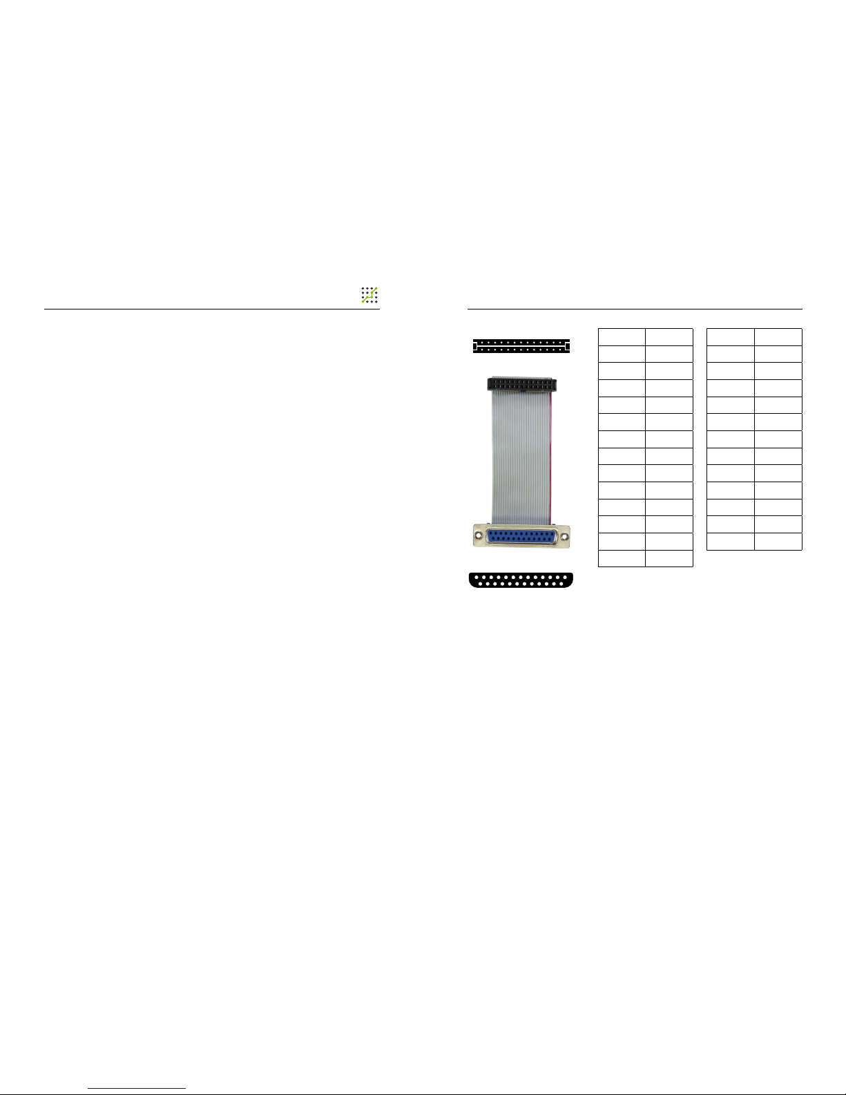
DB25 PIN IDC PIN
1 1
14 2
2 3
15 4
3 5
16 6
4 7
17 8
5 9
18 10
6 11
19 12
7 13
26 (Even) 2
25 (Odd) 1
13 1
25 14
Fig.1. Cable-adapter IDC26-DB25
20 14
8 15
21 16
9 17
22 18
10 19
23 20
11 21
24 22
12 23
25 24
13 25
NC 26
Page 4

7
PLCM-E3 CNC Ethernet controller
6
28.05.13 revision
Fig. 2. Connection diagram
IDC26
PINS PURPOSE
IN MACH3
input/Output
1 1 Output
2 14 Output
3 2 Output
4 15 input
5 3 Output
6 16 Output
7 4 Output
8 17 Output
9 5 Output
10 GND -
11 6 Output
12 GND -
13 7 Output
14 GND -
15 8 Output
16 GND -
17 9 Output
18 GND -
19 10 input
20 GND -
21 11 input
22 GND -
23 12 input
24 GND -
25 13 input
26
+5V
(disconnectable)
-
Fig. 3. Outputs purpose of XP1,
XP2, XP3 sockets
DB25
PINS PURPOSE
IN MACH3
input/Output
1 1 Output
2 2 Output
3 3 Output
4 4 Output
5 5 Output
6 6 Output
7 7 Output
8 8 Output
9 9 Output
10 10 input
11 11 input
12 12 input
13 13 input
14 14 Output
15 15 input
16 16 Output
17 17 Output
18 GND -
19 GND -
20 GND -
21 GND -
22 GND -
23 GND -
24 GND -
25 GND -
Fig. 4. Adapter outputs purpose
for XP1, XP2, XP3 ports
Page 5

9
PLCM-E3 CNC Ethernet controller
8
28.05.13 revision
Fig. 5. Cable type setting
5. SOFTWARE INSTALLATION AND SETTING
1. Turn on the controller and connect it to the Ethernet or USB
busbar (simultaneous connection through both interfaces is enabled).
Link LED should to light up in the process of Ethernet connection.
If LED doesn’t light up or blinks and network connection icon appears/
disappears in Windows, cable type automatic detection is incorrect (it
is caused by feature of some network interface cards). In this case, it is
required to adjust parameters manually. For this purpose go to “Start
– Control panel – Network and Sharing Center – Local Area Connection
– Properties”. Further press «Congure» (Fig. 5). Select “Speed/duplex
settings” property in “Advanced” window and set “10 Mbit/s full duplex”
value (Fig. 6). (Parameters and names in various network interface
cards can differ slightly from each other).
Fig. 6. Speed setting and Duplex
Operating Mode setting.
2. It is necessary to install PlugIn for device operation with
MACH3.
Download archive with PLCM series controllers software to
the address www.purelogic.ru/les/downloads/SOFT/PLCM.zip and
launch “setup.exe”. Controller Setup Wizard will open (Fig. 7).
Press “Next”. If you install software for the rst time and you
want that Setup Wizard install of necessary drivers, select devices
which it is planned to apply on this PC (Fig. 8). If any of devices isn’t
chosen, Setup Wizard will make only PlugIn updating for MACH3.
Fig. 7. Setup Wizard
Fig. 8. Driver installation
Page 6

11
PLCM-E3 CNC Ethernet controller
10
28.05.13 revision
Setup Wizard will suggest to perform automatic setting of PC
network adapter for correct connection with PLCM-E3 after “Next”
button pressing in the process of PLCM-E3 point choice (Fig. 9).
Automatic search procedure of the controller can break a work of local
network. Therefore use this function only if you don’t use local network
resources on this personal computer and you don’t use the Internet.
In search process controller should be connected to the local network.
Controller should be connected to PC using the USB interface
in Wizard operating process. It is required for the correct driver USB
installation.
Press “Next”, “Install”. Setup Wizard will copy necessary les and
will nish the work.
Fig. 9.
Network automatic installation
3. Select the corresponding PlugIn in a window presented at fig. 4.
when MACH3 runs after PlugIn installation
As a rule, in the list there are two PlugIn versions for PLCM
controllers: test and stable. Select that with which you want to work
at present. So that MACH3 doesn’t suggest to select PlugIn in each
launching it is necessary to place the tick «Don’t ask me again». If
there is a need to change the output device, select MACH3 menu item –
Function Cfg’s – Reset device sel.
If you decided to pass to another version, for example, last time you
were working with stable version, and now you want to try test version,
after launching you NEED to follow in PlugIn settings (see below) and to
update the controller internal software.
Fig. 10.
PlugIn choice.
Fig. 11.
PlugIn setting in MACH3
4. After successful PlugIn launching in MACH3 PlugIn Control
menu there will be a PLCM control item.
If image was appeared as in Fig.11 and you cann’t select the device
connected to Ethernet. It means that Windows Firewall blocks access
to PLCM-E3. It is necessary to add MACH3 in Firewall exceptions or to
disconnect a Firewall.
Page 7

13
PLCM-E3 CNC Ethernet controller
12
28.05.13 revision
5. Execute PlugIn setting.
It is necessary to select one of controllers connected to system from
the drop-down list. There will be controller additional settings (Fig.12)
after a choice. If PlugIn detects that the rmware became outdated, it
will be offered to update a rmware in the controller. It is enough to make
controller choice procedure once at the rst device installation.
Fig.12.
PlugIn setting in MACH3
Settings description:
Time of MACH3 look-ahead trajectory calculation - species
the data volume about a motion trajectory which the program
needs to prepare in advance, to count forward, it is a buffer. The
more this amount CNC operation is stabler. For example, MACH3
ceases to count new trajectory data during rotation of ToolPath
images. Therefore the more those are counted in advance,
motion «failure» probability is less during the image rotation or
another load of MACH3.
Time of PLMACH look-ahead trajectory calculation - the
similar buffer in PLCM board without MACH3 participating.
The buffer stabilizes work during short-term failures of
PLCM<>MACH3 connection and decelerations of MACH
calculation.
Remark: On the one hand the more value of these
parameters, the better (it is more buffer, operation is stabler). But
with buffer increase FeedHold will be delayed to the sum of these
two parameters, i.e. if MACH3 = 1 second buffer and PLMach =
0.5 second buffer, CNC system reaction time will be as the sum
of FeedHold =1.5 second pressing and step motor braking time
according to the pre-set prole of acceleration.
The logging
In the logging process the log-le of PLCM< > MACH3
interchange is saved in le «C:\MACH3\PLСM.log». If the device
operation is incorrect this le needs to be sent to Purelogic RND
technical support service with the detailed problem description.
Receive IP address automatically
We recommend to leave this point active if there is a DHCP
server in your local network (the device which can dynamically set
IP addresses; the usual house networking gateway for Internet
connection can be it).
Use the following IP address
It is necessary to use this variant if there is no the DHCP in
your network server xing IP addresses.
Press the OK button for setting process completion.
Page 8

Pay attention that documentation can be changed due
to constant technical upgrading of production.
You can download last versions from www.purelogic.ru
!
www.purelogic.ru
address: Bld. 160, Leninsky prospect,
Voronezh city, 394033, Russia
phone: +7 (495) 505-63-74,
+7 (473) 204-51-56
e-mail: info@purelogic.ru
 Loading...