

Page 1
Ver 1.1
USER MANUAL
MX
-
1800 / 3600
03/02/2009
Modular Digital Matrix Router
Page 2

Table of ContentsTable of Contents
1-4. NAMES AND FUNCTION OF EACH PART
2
2. TECHNICAL SPECIFICATION
(RS
232 / LAN / G
)
4-1.THE STRUCTURE OF
COMMAND CODE FOR RS
232 &
LAN COMMUNICATION
1. BASIC KNOWLEDGE OF THE PRODUCT
1-1. SAFETY INFORMATION AND INSTRUCTION
1-2. PACKAGE CONTENTS
1-3. PRODUCT FEATURES
1-5. INSTALLATION ENVIRONMENTS AND METHODS
2. PRODUCT INFORMATION
2-1. MX-3600 SYSTEM DIAGRAM.
-
3. HOW TO OPERATE
3-1 HOW TO CREATE CHANNELS
a. EDID Read and Save
b. Preview Mode
c. System Configuration
-
d. Preset Mode
3-2 ABOUT PRODUCT ID
3-3 RS-232C (COM PORT) COMMUNICATION PROTOCOL
3.3.1. PC Control Software
3.3.2. Hyper Terminal (ComMaster)
3-4 LAN (TCP/IP) COMMUNICATION PROTOCOL
3.4.1. PC Control Software
4. COMMUNICATION COMMAND CONFIGURATION
4-2. LAN COMMUNICATION
4-3. CONNECTOR PIN ASSIGNMENT
5. WARRANTY INFORMATION
eneral Configuration
-
ABOUT RETURN OF GOODS
Page 3
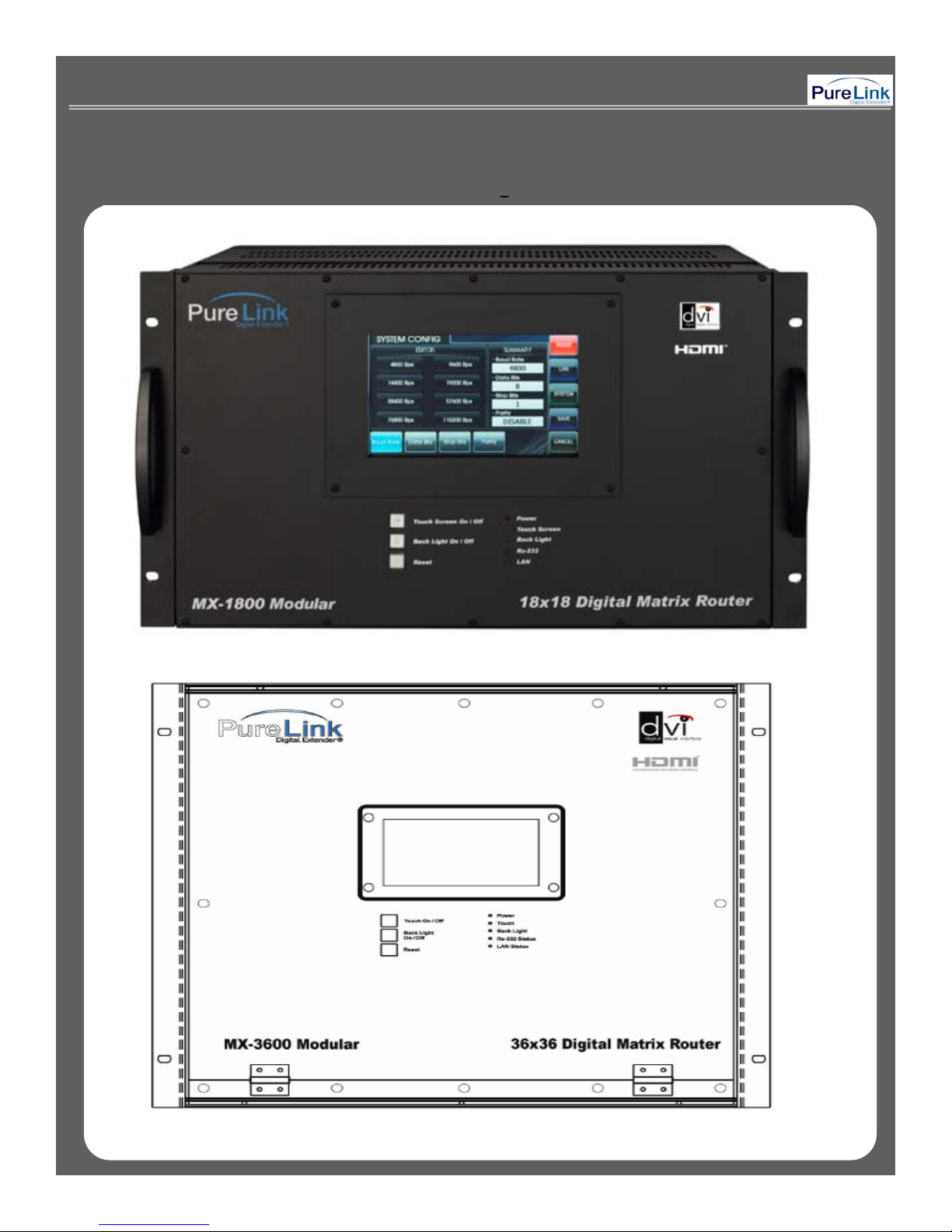
MX Series Front Panel DiagramMX Series Front Panel Diagram
gg
< MX-1800 Modular Matrix Router>
3
< MX-3600 Modular Matrix Router>
Page 4
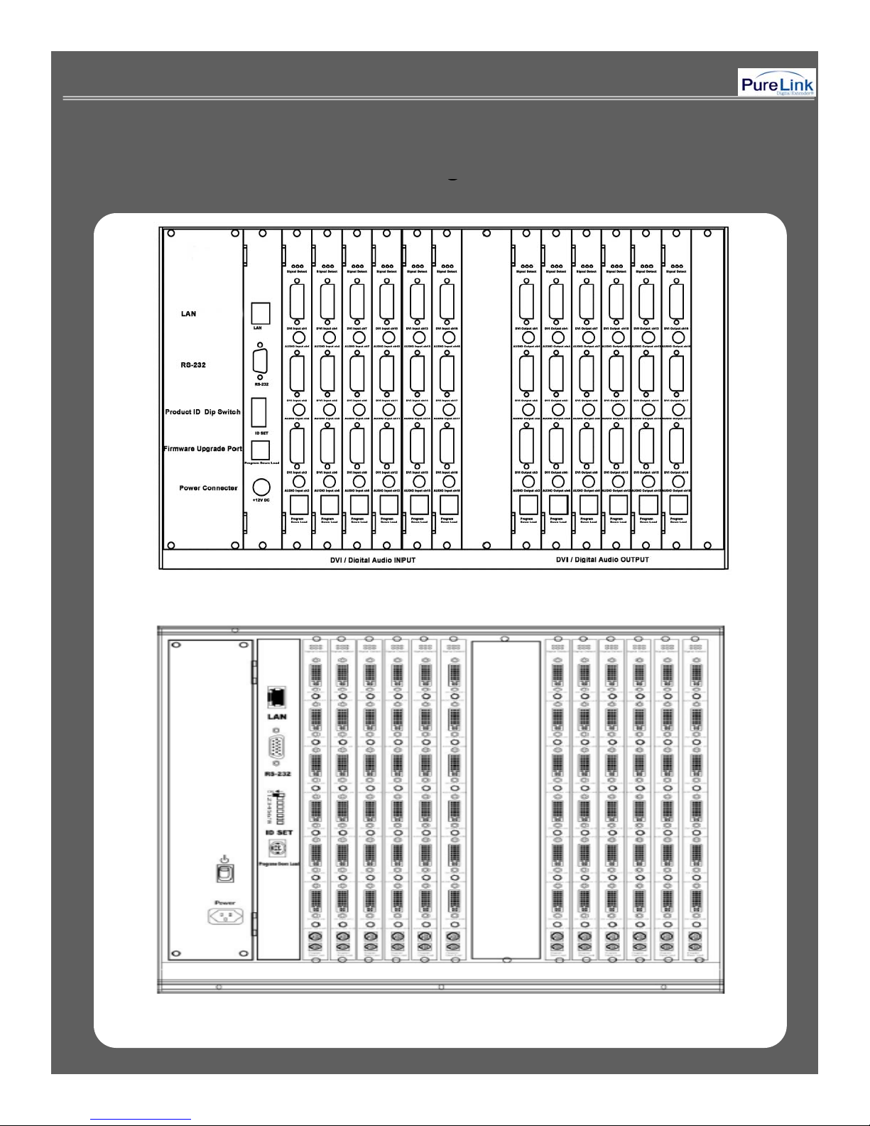
MX Series Rear Panel DiagramMX Series Rear Panel Diagram
gg
< MX-1800 Modular Matrix Router>
< MX-3600 Modular Matrix Router>
4
Page 5
1. Basic Knowledge Of The Product1. Basic Knowledge Of The Product
Unpl
thi
Please refer to the user manual guide if the product has to be operated by using other type of power
O
tilati
Keep it away from liquid, magnetic, inflammable substances.
11--1 Safety Information and Instruction1 Safety Information and Instruction
▪ All the safety and user manual should be read before the appliance is operated.
▪ The safety and operating instructions should be retained for future reference.
▪
ug
s product from the wall outlet before cleaning. Do not use liquid cleaners or aerosol cleaners.
Use a damp cloth for cleaning.
▪ Do not use this equipment near areas of running water or dense condensation.
▪ This product should be operated by a proper power source s indicated on the marked label.
If you are not sure of the type of power supplied to your home, consult your local electricity company.
source, such as portable battery power supply.
▪ This equipment may be equipped with a 3 wire grounding-type plug, a plug having a third (grounding) pin.
This pin will only fit in to a grounding type power outlet. This is a safety feature. In addition , this equipment
should be plugged into a properly grounded outlet in order to avoid electric shock. Do not bypass the
grounding features of the power cable or plug.
▪
pening in the cabinet are provided for ven
on and to ensure reliable operation of the equipment and to
protect it from overheating. The openings should never be blocked.
▪ Do not use any damaged power cords or plugs, or loosed outlets, this may cause electrical shock or fire.
▪ Do not put any heavy object on this equipment.
▪
▪ Turn off power before insert or take out INPUT/OUTPUT slot card.
▪ Input/Output cards may be damaged when they are replaced with power turned on.
If you experience any malfunctioning of product or have any question as to operation of the product,
please contact our customer service center.
Dtrovision, Inc.
Tel: 201-488-3232
5
Page 6
According to Council Directive 73/23/EEC (February 19, 1973) on the Harmonization of the Laws of Member
▪
User s manual
▪
Flexible EDID Management feature
Declaration of Conformity
States relating to Electrical Equipment; Council Directive 89/336/EEC (May 3, 1989) on Electromagnetic
Compatibility; Council Directive 93/68/EEC (July 22, 1993)-Amen din g Directives 89/336 /EE C (MC) and
73/23/EEC (Low Voltage Equipment Safety), and/or CPU Boards and Power Supplies used Council Directive
93/68/EEC with Matrix, Dtrovision LLC., 9A Bergen Turnpike Little Ferry, NJ 07643 201-488-3232, declares
under sole responsibility, that the product identifies with 93/66/EE C of the Council Directive Low Voltage
Equipment Safety. Each product marketed is identical to the representative unit tested and found to be compliant
with the standards.
11--2 Package Contents2 Package Contents
▪ Main body: MX-1800 / MX-3600
▪ Power adapter: DC12V, 12A
▪ RS-232C & LAN cables
’
11--3 Product Features3 Product Features
Digital Matrix Router (MX-1800/3600) is an integrated digital processor that supports all kinds of digital interfaces
such as DVI, HDMI, which are applied to most digital products. MX Matrix Series are designed to meet
customers’ demands by providing prompt availability of DVI or HDMI Input / Output cards. MX-1800 allows you to
populate the Input/ Output card with any connection (DVI or HDMI) you like and expand as needed.
▪ 19” standard rack mountable (6U).
▪ Support up to 18 (36) input / output channels.(MX-1800 /MX-3600)
▪ Enable to insert different combination of DVI/HDMI Input / Output cards.
.
▪ Plug-and-play which makes set up and installation much easier.
▪ Compliant to High-bandwidth Digital Content Protection (HDCP)
▪ Supports high resolution up to WUXGA(1920x1200)@60Hz, 1080p@60Hz
▪ Convenient control methods:
- Control via front panel touch screen
- Control via LAN (TCP/IP).
- Control via RS-232C port
▪ It has an instantaneous noise protection circuit built in input and output ports therefore it can protect expensive
equipment from fault caused by noises (if any).
▪ Any latest firmware version can be upgraded via supplied download cable.
6
Page 7
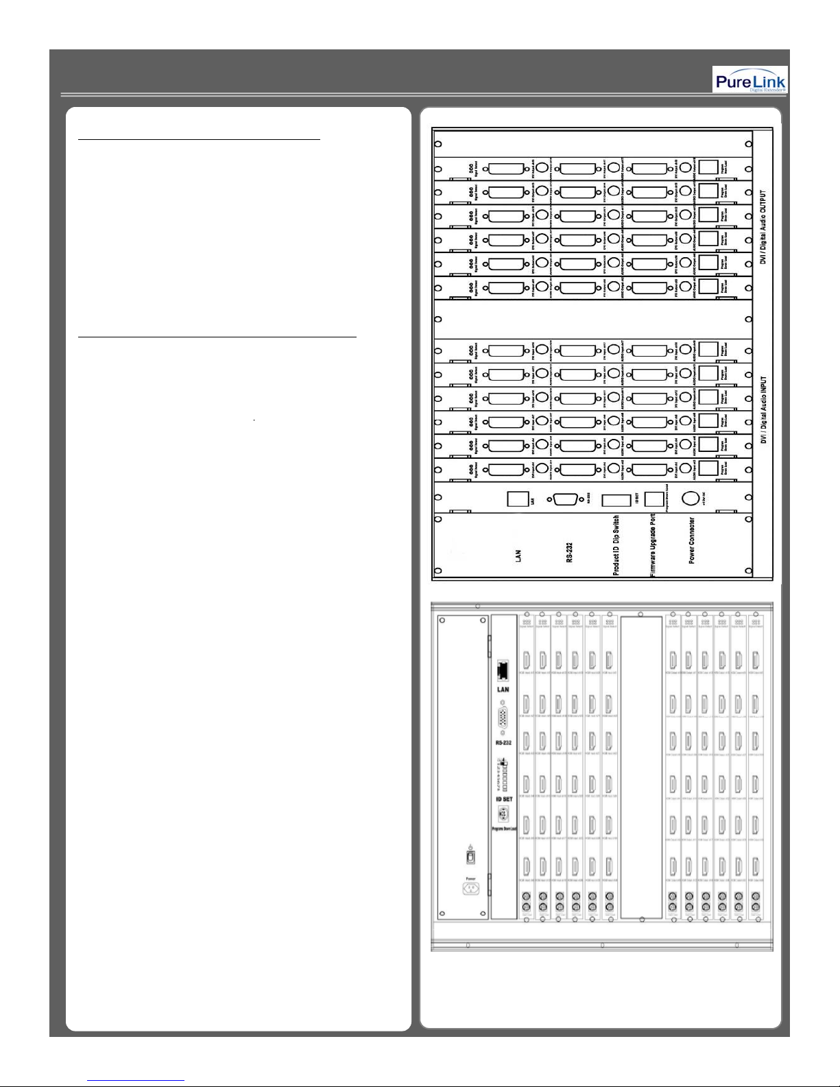
11--4 Names and Function of Each Part4 Names and Function of Each Part
)
(
)
•
HDMI Input / Output card with 3 or 6 ports
p
)
p( )
▪
Recommend stabilized AC input power
• Main Chassis (For MX-1800 or MX-3600
• DVI Input / Output card with 3 or 6 ports, digital
coaxial audio, HDCP compliant.
• DVI Input / Output card with 3 or 6 ports, digital
coaxial audio, Non-HDCP.
.
11--5 Installation environments and methods5 Installation environments and methods
▪ For installation environments, we recommend the
following environments for our matrix.
▪ Below 30°C of ambient tem
erature(Best condition
▪ Install and operate in the environment below 60%
of ambient humidity (Best condition)
▪ Use it in the environment of free of vibrations and
dusts and in good ventilation condition
(Recommend to use AVR).
< Picture A - 1 >
7
Page 8
2. Functions of the product2. Functions of the product
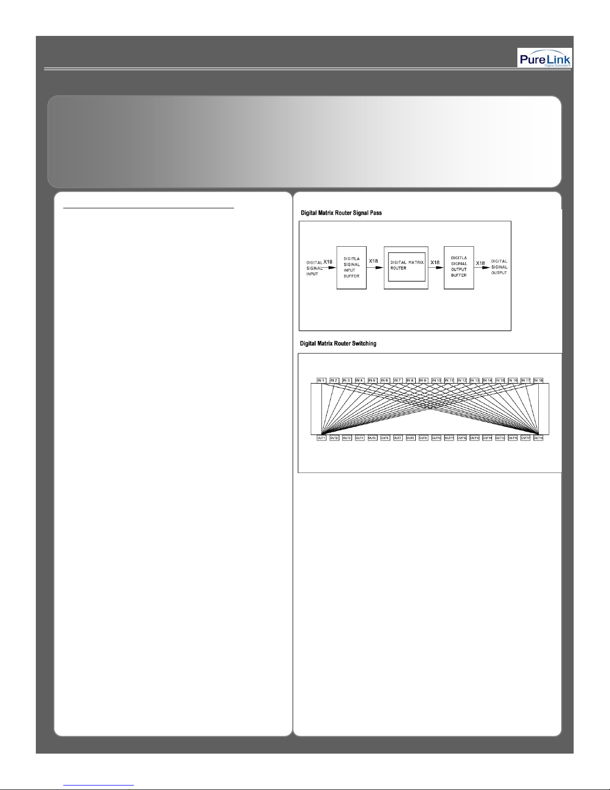
22--1. MX1. MX--1800 / 3600 System Diagram1800 / 3600 System Diagram
Any combination of input channel can be routed to
any output channel or single input channe l can be
assigned to multiple output channel by using front
touch panel, RS-232c or LAN (TCP/IP)
communication port.
< Picture B - 1 >
8
Page 9

22--2 Technical Specification 2 Technical Specification
ps (
p( g )
P
iti
▪ Type of signals: TMDS signals, digital R.G.B. 2k
▪ HDMI data transmission band: 2.25 Gbps (single link).
▪ DVI-D data transmission band: 1.65 Gb
single link).
▪ HDMI version 1.3 with deep color 36 bits
▪ Resolutions: VGA (640*480) ~ WUXGA (1900*1200)@60Hz, 720p~1080i/p.
▪ Audio IN/OUT: digital audio coaxial (In DVI board only)
▪
anel: 7 inch touch panel, pressure recogn
on sensor
▪ Port switch control: Front LCD touch panel, RS-232C port, LAN port.
▪ Input / output port: Input 18(36) / output 18(36)
▪ Input / output connector: DVI-D 29 pin Female or HDMI 19 pin Female
▪ Power source: DC12V, 12.5A
▪ Power consume: 100Watts/max : 120Watts.
▪ Size (Width * Length *Height, INCH): 17.2” * 10.2” * 10.5”. (MX-1800) / 19” * 10.5” * 17.5” (MX-3600)
▪ Weight: 26.5 lbs (MX-1800) / 46 lbs (MX-3600)
9
Page 10
3. How to operate3. How to operate
PREVIEW:
Preview the status of selected input/output
33--1 How to Create Channels1 How to Create Channels
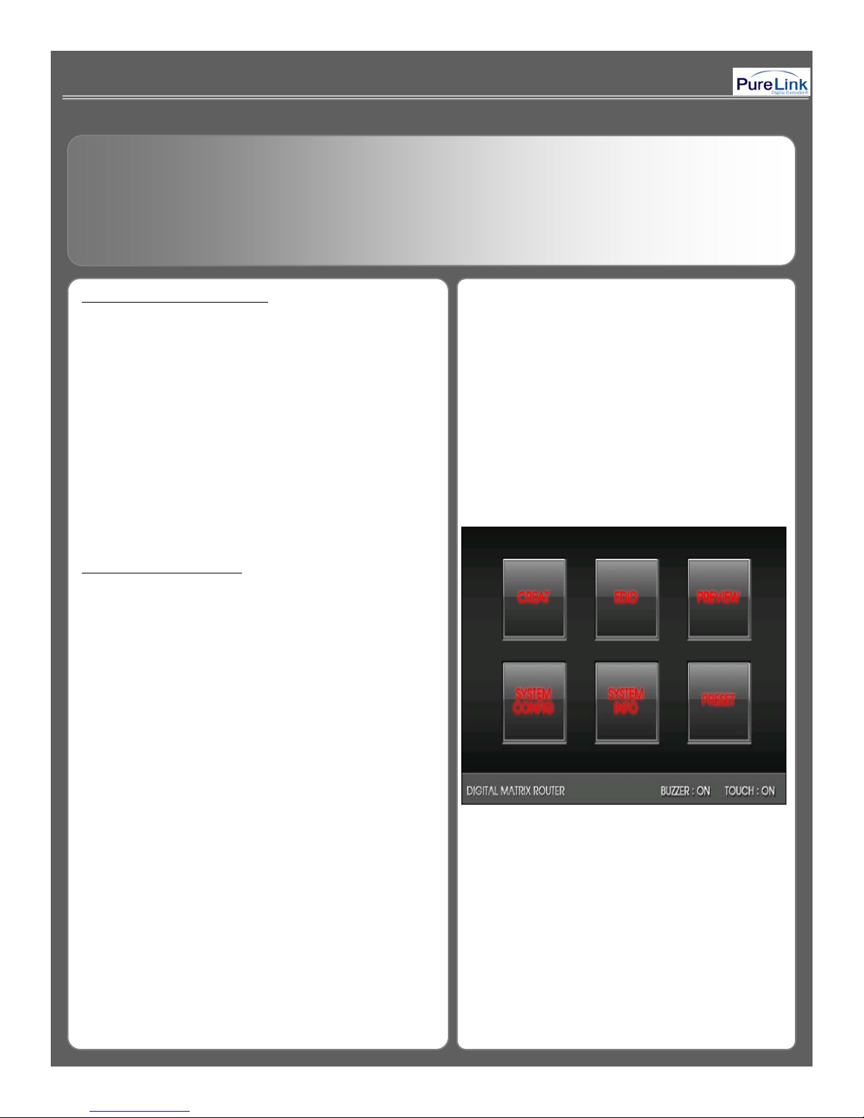
When matrix is turned on, the front touch panel LCD
display will show the list of Main Menu as follows:
Power switch: Power On/Off
Touch On/Off: Touch panel operation On/Off
Back Light On/Off: Touch panel backlight On/Off
Reset: System reboots after press and hold the button
for 3~4 seconds
Touch Panel Main Menu
CREATE: To create input/output chan ne l
EDID: Read and save the EDID data from connected
display device
channel or EDID setting
SYSTEM CONFIG: Allows to change the system setting
SYSTEM INFO: Review the general configuration of the
system
PRESET: preset input/output channels which are often
used
<Please refer to Picture C-1>
< Picture C - 1 >
10
Page 11
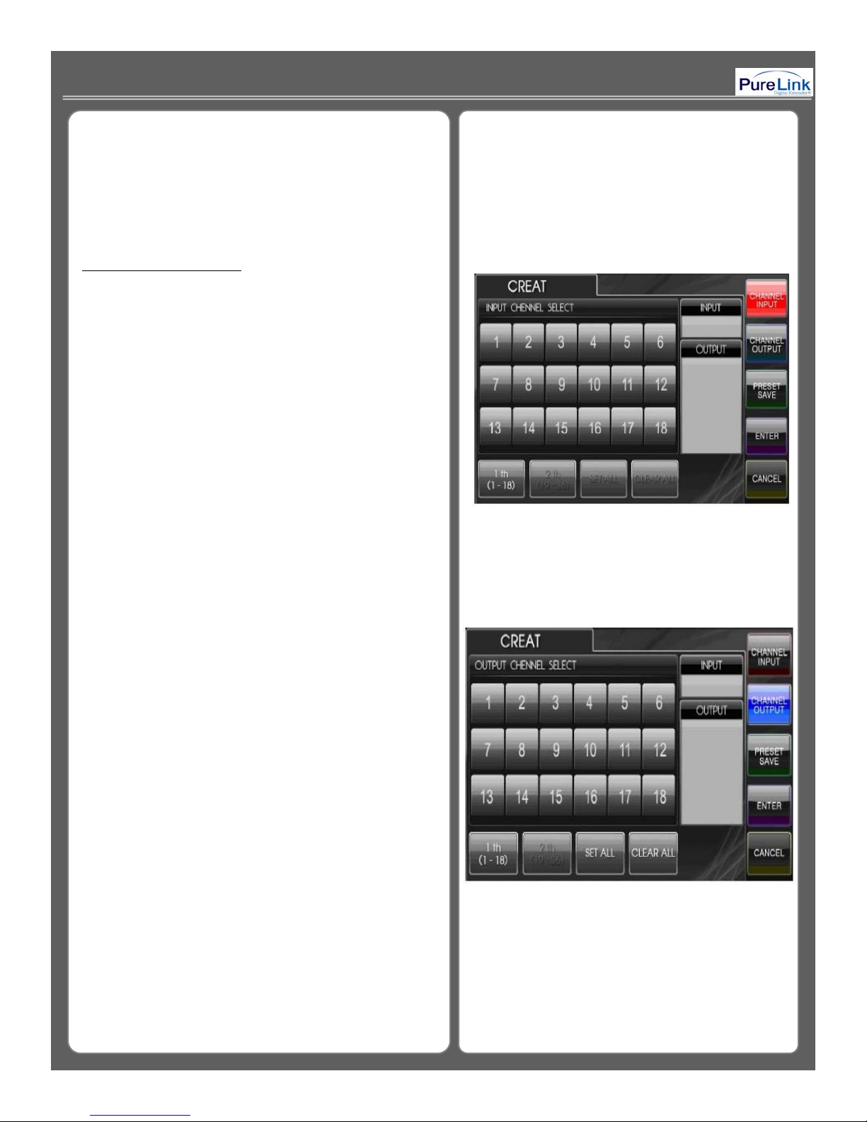
How to Create Channel:
<Please refer to Picture C
2>
Step 2. Press CHANNEL OUTPUT button
select
Select Input / Output channel: When CREATE icon on
main menu is selected, Pic. C-2 will appears on the
front LCD display.
Step1. CHANNEL INPUT menu -> Select any Input
channel -> Go to Step 2.
-
->
Output channel (multiple output channel can be selected)
-> Go to Step 3.
*Press CANCEL button to cancel the current job ->
return to main menu
SET ALL: Select all output
CLEAR ALL: Cancel all selection
<Please refer to Picture C-3>
< Picture C - 2 >
< Picture C - 3 >
11
Page 12
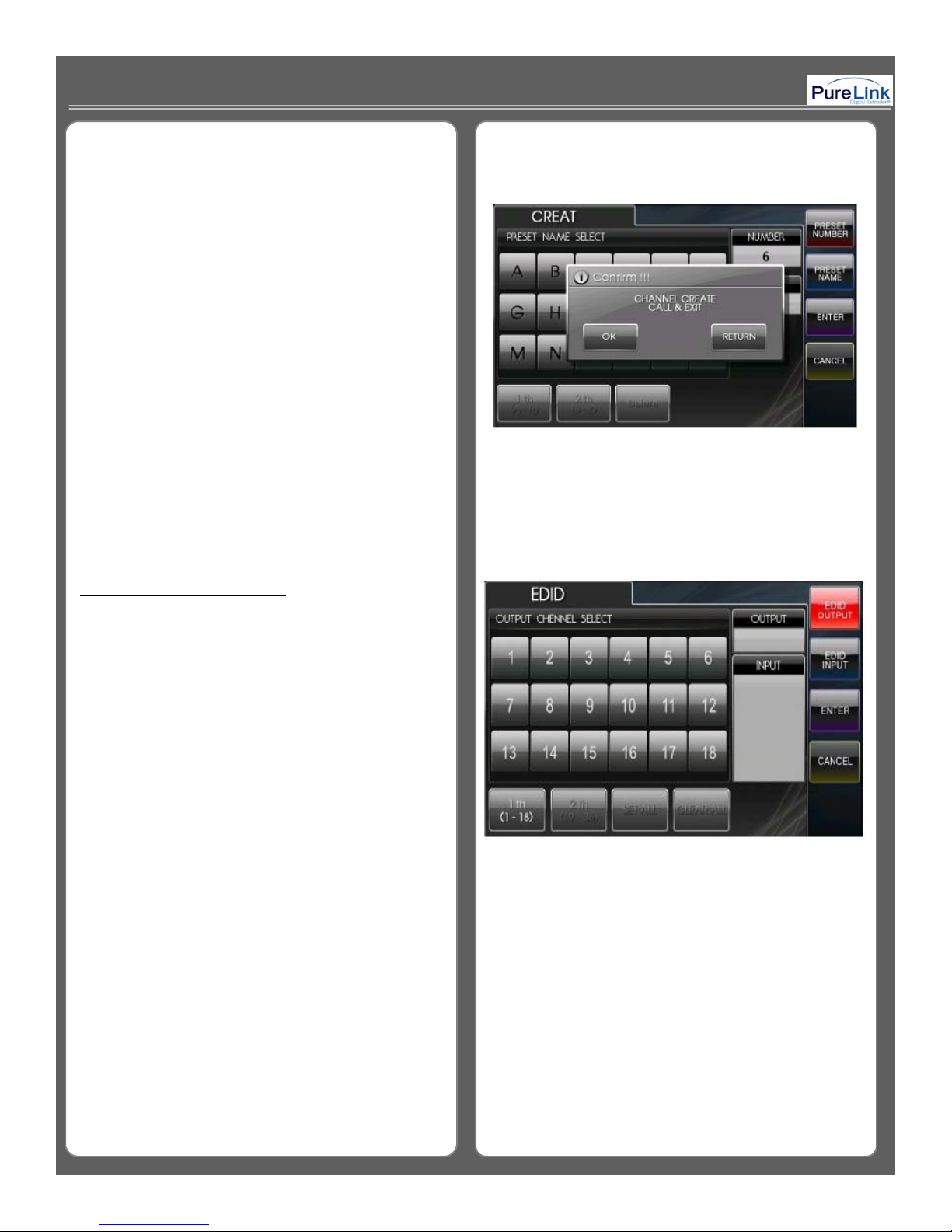
Step 3. Confirmation
OK: Finish the channel set up ->return to main menu
RETURN: Returns to CHANNEL OUTPUT menu
<Please refer to Picture C-4>
< Picture C - 4 >
How to read and save EDID:
Read and Save EDID : If EDID icon is selected,
Pic. D-1 will appears on the front LCD display.
<Please refer to Picture D-1>
< Picture D - 1 >
12
Page 13
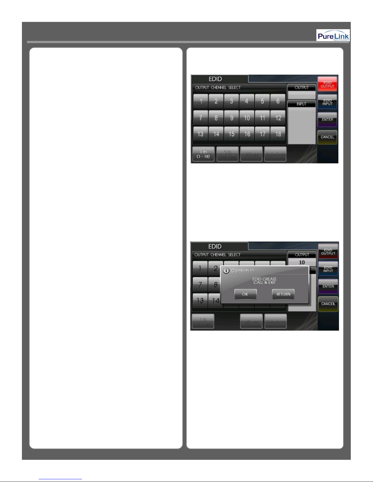
Step1. OUTPUT EDID SELECT menu -> select
OUTPUT channel (to retrieve EDID information from
connected display device.) -> go to Step 2.
<Please refer to Picture D-2>
< Picture D - 2 >
Step 2. Press EDID INPUT button -> select INPUT
channel (one or multiple input channel can be
selected) -> press ENTER button to confirm.
SET ALL: Select all output
CLEAR ALL: Cancel all selection
OK: Finish the EDID save -> return to main menu
RETURN: Returns to INPUT EDID SELECT menu
<Please refer to Picture D-3>
< Picture D - 3 >
13
Page 14
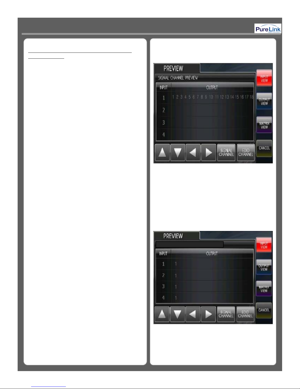
3-1b Preview of Input and Output Channel or
right side
<Please refer to Picture D
5>
EDID selection:
When PREVIEW icon is selected, Pic.D-4 will
appears on the front LCD display.
INPUT VIEW: View the status of selected Input
channel
OUTPUT VIEW: View the status of selected Output
channel
MATRIX VIEW: View the status of selected all
input/output channel on single display
ARROW: Move the screen to front, back, left and
CANCEL: Return to main menu
<Please refer to Picture D-4>
< Picture D - 4 >
When EDID Channel button is selected, EDID
PREVIEW menu shows as Pic.D-5
INPUT VIEW: View the status of selected input
channel
OUTPUT VIEW: View the status of selected output
channel
MATRIX VIEW: View the status of selected all
Input / Output EDID setting
ARROW: Move the screen to front, back, left and
right side
CANCEL: Returns to the main menu
-
EDID CHANNEL PREVIEW
< Picture D - 5 >
14
Page 15
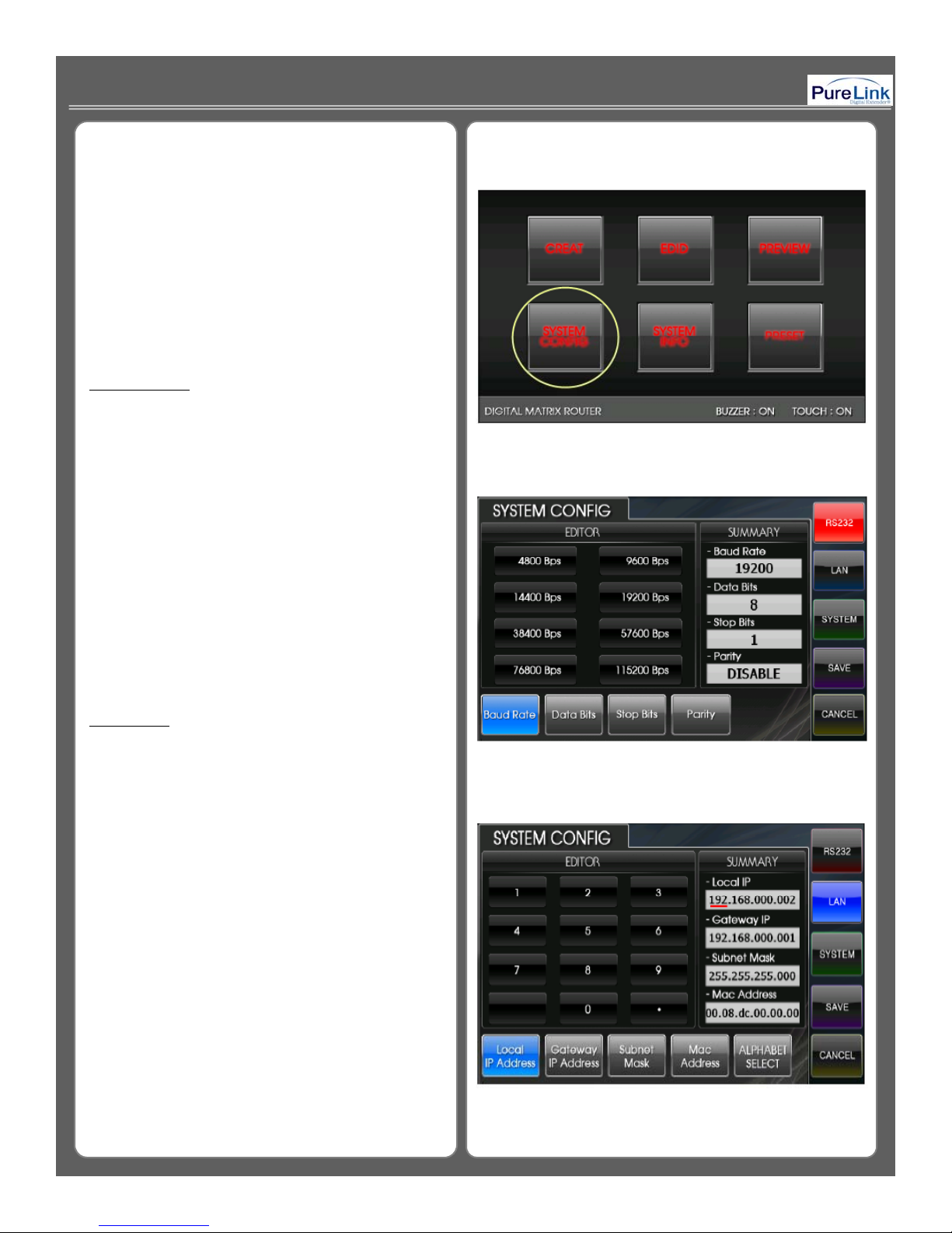
System Configuration: When SYSTEM CONFIG
is selected
Pic. E-1 will appears on the front LCD
DATA Bits:
Set up data bits, default: 8 bit
Local IP Address:
Set up local IP address
,
Display.
SYSTEM CONFIG is designed to change the
configuration of RS-232, LAN, and SYSTEM.
<Please refer to Picture E-1>
RS-232 Setup
Baud Rate: Set up communication speed for
RS-232, default: 19200bps
Stop Bits: Set up stop bits, default: 1 bit
< Picture E - 1 >
Parity: Confirm parity, default: Disable
SAVE: Save any change you make
CANCEL: Returns to the main menu
<Please refer to Picture E-2>
LAN Setup
,
default: 192.168.000.002
Gateway IP Address: Set up Gateway IP Address,
default: 192.168.000.001
Subnet Mask: Set up Subnet Mask,
default: 255.255.255.255
Mac Address: Set up Mac Address,
default: 00.08.DC.00.00.00
ALPHABET SELECT: Select alphabet and number
< Picture E - 2 >
SAVE: Save any change you make
CANCEL: return to main menu
<Please refer to Picture H-3>
15
< Picture H - 3 >
Page 16

SYSTEM GENERAL CONFIGURATION
SYSTEM INFO shows the current status of channel
When SYSTEM icon is selected,
Pic E-4 will appear on the front LCD display.
Buzzer: Buzzer sound On/Off
SAVE: Save any change you make
CANCEL: Return to main menu
<Please refer to Picture E-4>
< Picture E - 4 >
SYSTEM INFORMATION
Configuration, LAN Config., RS232 Config., and
General system information
CANCEL: Returns to the main menu
<Please refer to Picture E-5>
< Picture E - 5 >
16
Page 17
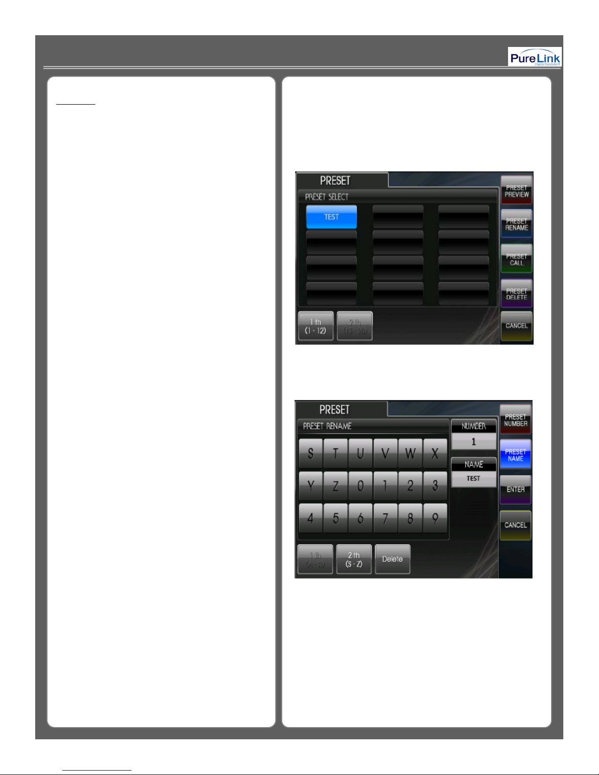
PRESET
groups of preset. For example, lets say you want
selected by preset number
It allows users to have up to 20 different
to use only 4 inputs & output channel and assign
them in certain order. Then PRESET feature will
help saving previous assignment.
PRESET PREVIEW: View the status of saved
preset Channels
PRESET RENAME: Change the saved preset
number and name
PRESET CALL: Change the current channels
to one of the selected preset
PRESET DELETE: To delete any preset as
needed
CANCEL: Returns to the main menu
<Please refer to Picture F-1>
PRESET NAME: Change the name of preset
Up to 12 letters can be used to
make name for selected preset.
SAVE: Save changed name
CANCEL: Returns to the main menu
<Please refer to Picture F-2>
< Picture F - 1 >
.
< Picture F - 2 >
17
Page 18
Preset Save: Create -> Input -> Select One or
If you done selecting all Input and Output
>Enter
located on rear panel and ID number must be
Multiple #-> Output-> Select One or Multiple ## ->
> Preset Save ->Preset Number -> Select # ->
Preset Name ->Input Name->Save
Preset Call: Preset Call-> Select Preset Name ->
Preset Call
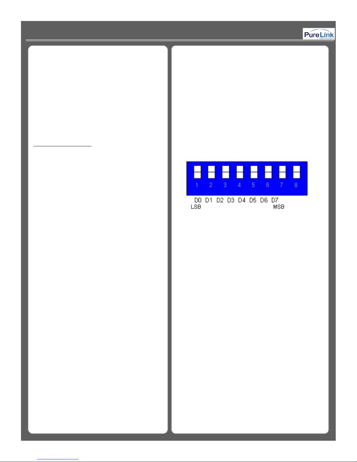
33--2 About Product ID2 About Product ID
▪ Product ID setting (use of DIP switch)
▪ The Product ID can be changed via DIP switch
selected within ID number 1~255. if the ID
number is set to “0”, it will become invalid
number.
▪ It needs to be set up in order to identify the
matrix when it attempts to communicate with
external controller or PC control program.
▪ It’s in the form of binary number.
<Please refer to Picture G-1>
-
*The factory default product ID is always set to “1” *
< Picture G - 1 >
For example;
Product ID = 01 (00000001b) –
1 ON, 2 OFF, 3 OFF, 4 OFF,
5 OFF, 6 OFF, 7 OFF, 8 OFF,
Product ID = 10 (00001010b) –
1 OFF, 2 ON, 3 OFF, 4 ON,
5 OFF, 6 OFF, 7 OFF, 8 OFF,
Product ID = 23 (00010111b) –
1 ON, 2 ON, 3 ON, 4 OFF,
5 ON, 6 OFF, 7 OFF, 8 OFF
18
Page 19
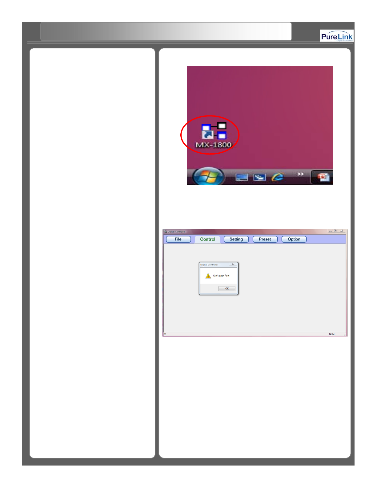
33--3. RS3. RS--232C (COM PORT) Communication Protocol232C (COM PORT) Communication Protocol
configuration, Can t open port! Message window
RS-232C
PC Control Software
Step 1. Click MX-1800 icon to execute the PC
Digital Controller program.
<Please refer to Picture H-1>
< Picture H - 1 >
Step 2. When the PC COM port number you
choose doesn’t correspond with the control program
will appears. Therefore you must to check your
COM port setting before you execute the Digital
Controller.
<Please refer to Picture H-2>
“
’
”
< Picture H - 2 >
19
Page 20
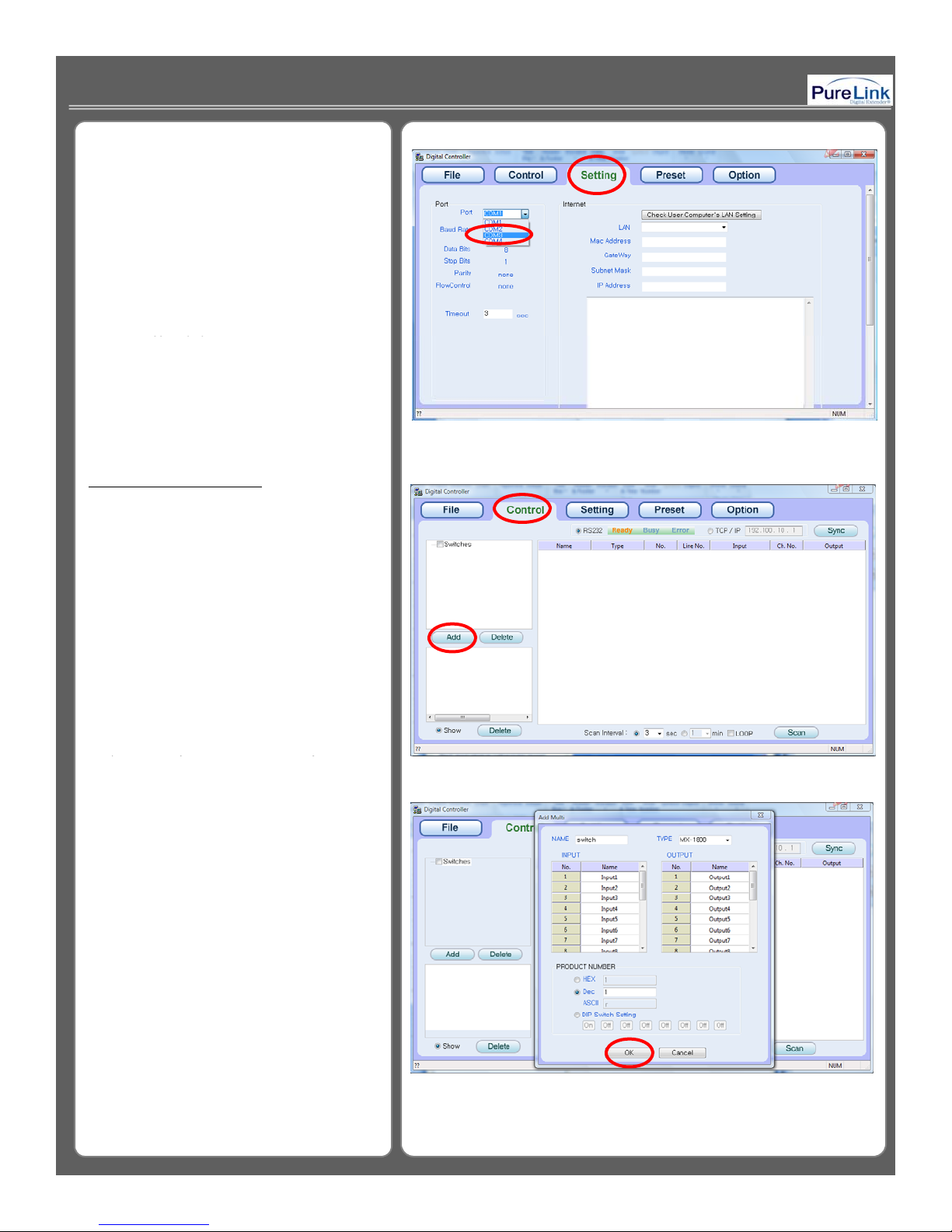
command
py ,y
value
Step 3. Go to “Setting” on the tab menu and
select valid COM port.
Port: Select the communication port #1 through #4
Baud Rate: Select the Baud Rate which is
correspond to the connected matrix
switcher.
Timeout: Configure the delay time for each control
<Please refer to Picture H-3>
ADD YOUR MATRIX ROUTERADD YOUR MATRIX ROUTER
Step 1. Go to “Control“ and click “Add” button to
add the matrix you want to connect with.
<Please refer to Picture H-4>
< Picture H - 3 >
Step 2. Before you click on OK button, you can
assign a name to each input and output
channel the way you like.
NAME: Create the switcher title
TYPE: A fixed selection of MX1800 or MX-3600
INPUT: You can assign a name to each
Input channel
OUTPUT: You can assign a name to each
Output channel
Product Number: It is same as Product ID number.
*You can select the ID number from 01
to 99 for Decimal value, and by doing it,
HEX and ASCII value automatically
change to the same value as Decimal
.
<Please refer to Picture H-5>
< Picture H - 4 >
< Picture H - 5 >
20
Page 21
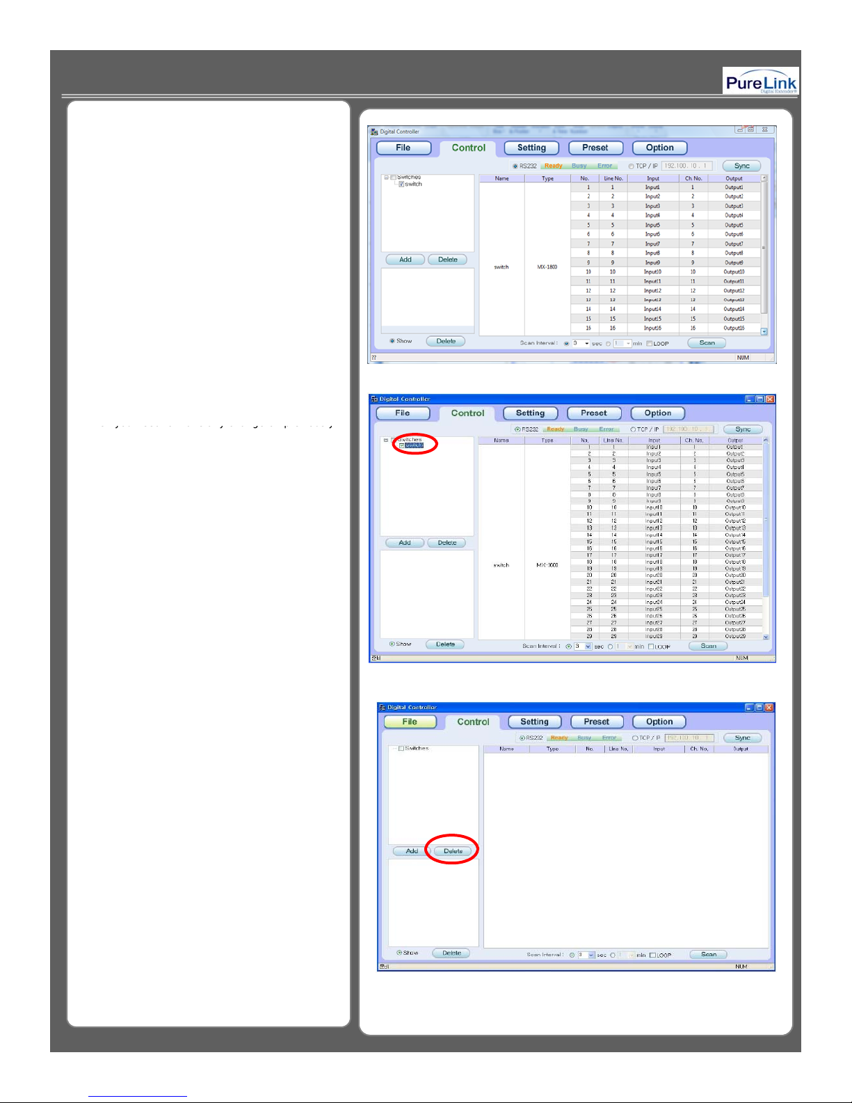
When you need to make any change on previously
< Picture H
>
Step 3. Now you can see an added switch
and the list of channels
<Please refer to Picture H-6>
To modify the added switcher:
added switcher setting, you can go back by doubleclick on added switcher from the list of switcher box
<Please refer to Picture H-7>
< Picture H - 6 >
To delete the added switcher:
When you want to delete the added switcher from
the switcher list, you need to select and highlight
the switcher, then click on Delete key.
<Please refer to Picture H-8>
-
7
< Picture H - 8 >
21
Page 22
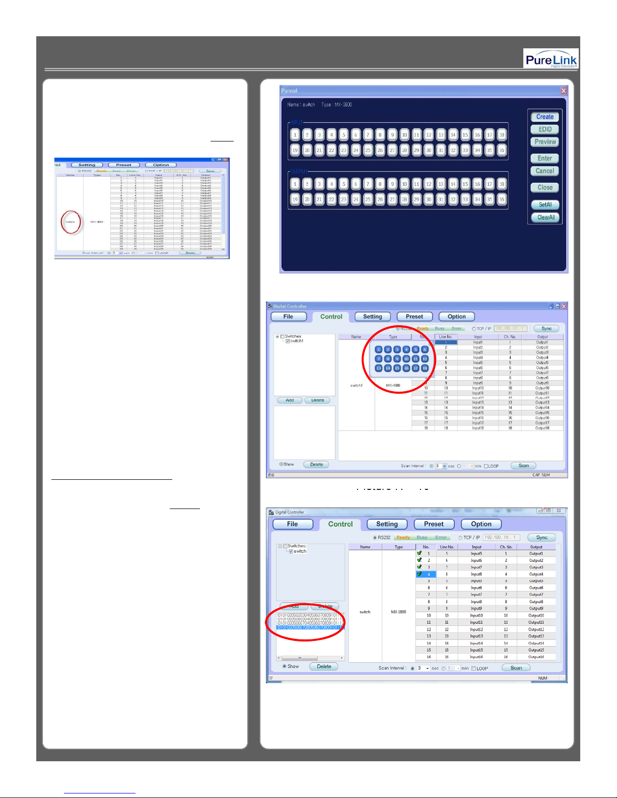
To use Pannel window:
easily performed by using the
Pannel
window
SetAll
: Select all Input & Output Channel
Picture H
10
channel, click on Scan to start the scan
Selecting and changing input/output channel can be
To activate the Pannel window, double click NAME
column as shown under.
Create: Use to create a new input/output channel
EDID: Register EDID information
Preview: Shows the detail and condition of current
setup
Enter: Create and Save
Cancel: To cancel the configuration
Close: To close PANNEL window
.
< Picture H - 9 >
ClearAll: Unselect all channel
< Please refer to Picture H-9>
CHANNEL SWITCHING & SCAN
Step 1. When you click on any Line No., you
will see a number selection box which
allows you to choose or change the input
channel.
*Line No. represents the Input channel
*No. represents the Output chann el
<Please refer to Picture H-10>
Step 2. You can select which channel to scan by
clicking on any No. box. The selected No.
box will have a green checkmark on it. The
time of scan interval is adjustable from 1-8
second or 1-8 minutes. After selecting the
.
* If you look at the bottom of left corner, it will show
the list of command code that is being transmitted
to the Matrix router.
<
-
< Picture H - 11 >
>
22
<Please refer to Picture H-11>
Page 23
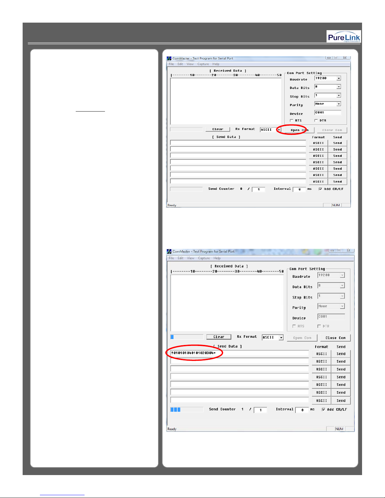
RS-232C
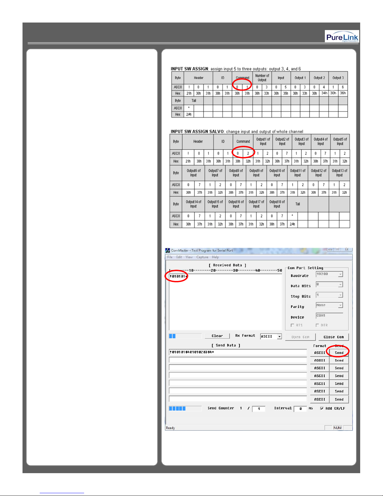
!010101040101020304
2. Hyper terminal or other applications
(For your convenience, we developed
an external control software program
called “Com-master”.)
Step1. Execute ComMaster program and
click “Open Com” button.
<Please refer to Picture I-1>
Step2. In Pic I-2, it is shows a command code
as an example; to route input 1 to output
1,2,3 and 4.
*ASCII command code:
*
.
<Please refer to Picture I-2>
*You can find more sample command
code on page 30.
< Picture I - 1 >
< Picture I - 2 >
23
Page 24
RS-232C
product ID is set to 01
Example of communication code when
product ID is set to “01”.
Example of communication code when
“
”
.
<Please refer to Picture I-3>
.
Step3. Click “Send” button. If the command
code you send is correct, you will see a
response value !010101* on the Received
Data window
<Please refer to Picture I-4>
< Picture I - 3 >
< Picture I - 4 >
24
Page 25
RS-232C
Nothing Ch
!
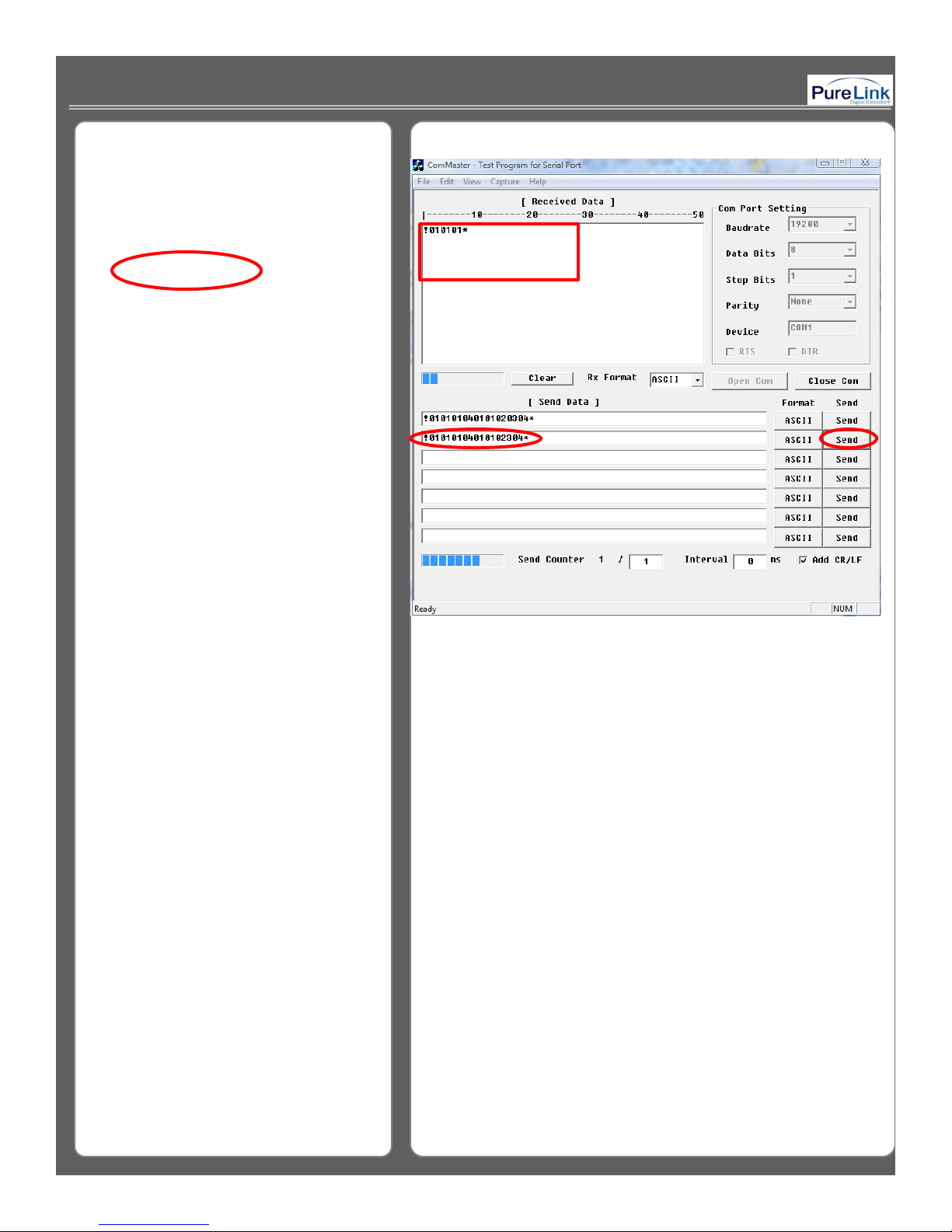
When an incorrect command is send to the
matrix router, there won’t be any response.
Example of Incorrect command
!0101010302304*
<Please refer to Picture I-5>
anged
< Picture I - 5 >
25
Page 26
33--4. LAN (TCP/IP) Communication Protocol4. LAN (TCP/IP) Communication Protocol
LAN (TCP/IP)
PC Control SoftwarePC Control Software
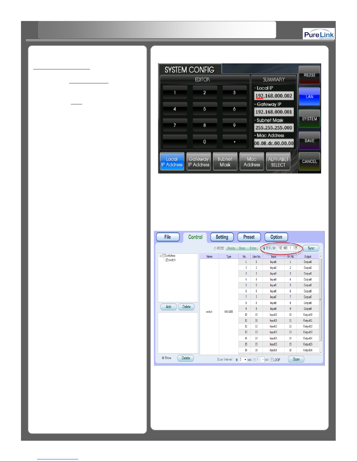
Step 1. Go to System Configon the touch
panel screen.
Step 2. Select LAN
network configuration.
Local IP Address: Set up local IP
Address / default: 192.168.000.002
Gateway IP Address: Set up Gateway IP
Address / default: 192.168.000.001
Subnet Mask: Set up Subnet Mask /
Mac Address: Set up Mac Address/
Step 3. Execute MX-1800 / 3600 control
program.
Step 4. Enter the same IP address as you
already set up in the router. Your
LAN connection is now complete.
icon to set up the
default: 255.255.255.255
default: 00.08.DC.00.00.00
< Picture J - 1 >
< Picture J - 2 >
26
Page 27
33--4. LAN (TCP/IP) Communication Protocol4. LAN (TCP/IP) Communication Protocol
Internet Explorer LAN Control PageInternet Explorer LAN Control Page
LAN (TCP/IP)
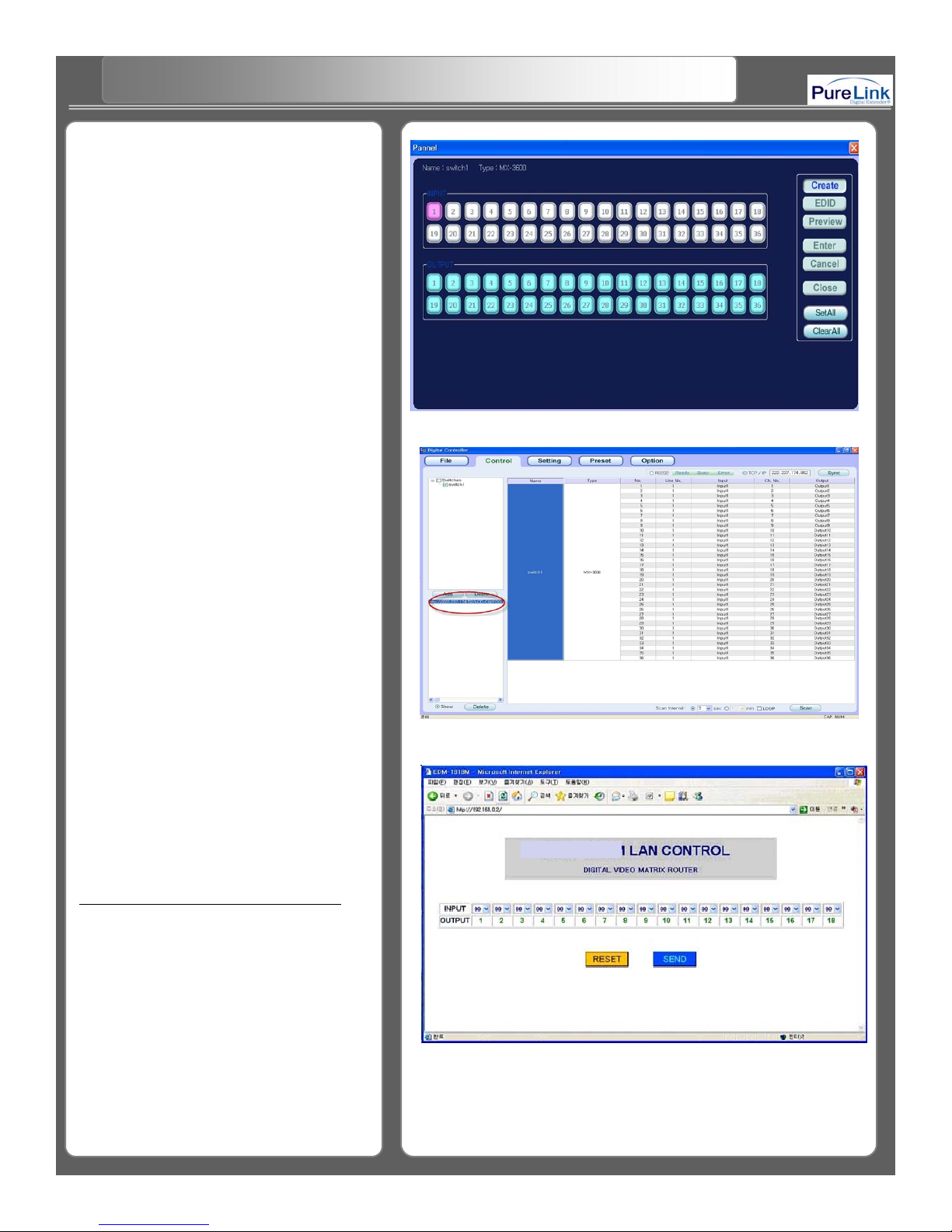
Step 5. Open the Pannel window to
create any channel. In J – 3, the
input #1 channel is being routed to
all output channels
Step 6. Press enter key to create channel
and close Pannel window.
Step 7. Now, Input #1 is assigned to all
output channel and you can confirm
whether the command has been
sent to router by checking the
command data at the bottom of left
corner. <Please refer to Pic J-4>
< Picture J - 3 >
After you open the web browser and
apply the same IP address as the one
you already configured in your matrix
Router, you will be connected to LAN
Control page and able to switch channel
or reset the router.
If you select Input channel for output and
press SEND, the channel will be changed.
<Please refer to Picture J-5>
< Picture J - 4 >
MX-1800 /360
0
< Picture J - 5 >
27
Page 28
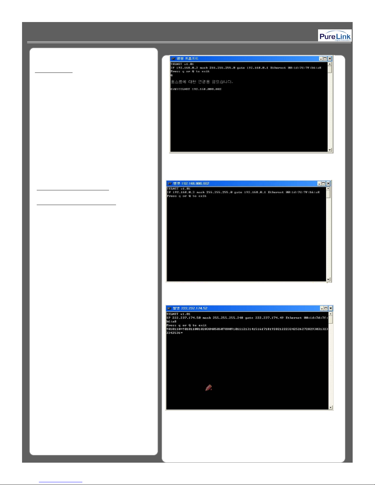
LAN (TCP /IP)
Correct : 192.169. 233. 12
TelNetTelNet Setup Setup
When you use Telnet via LAN port, it
enable you to remotely control Window
DOS prompt, Hyper Terminal, and
the Telnet program. (Control code is
correspond with RS-232 command.)
*Note: When you attempt to use either
Telnet or Internet Explorer to communicate
with the router, you must not input “0”
value in the last three digits of IP address
otherwise connect cannot be accomplished
Incorrect : 192. 169. 233. 012
<Enter the router IP address
e.g.) TelNet + IP Address then press enter>
< If Telnet is successfully connected, LAN setting information
will appears on the window>
<To confirm the setting, you need to send the following code:
!010110* and then you will be receiving the response value>
28
Page 29
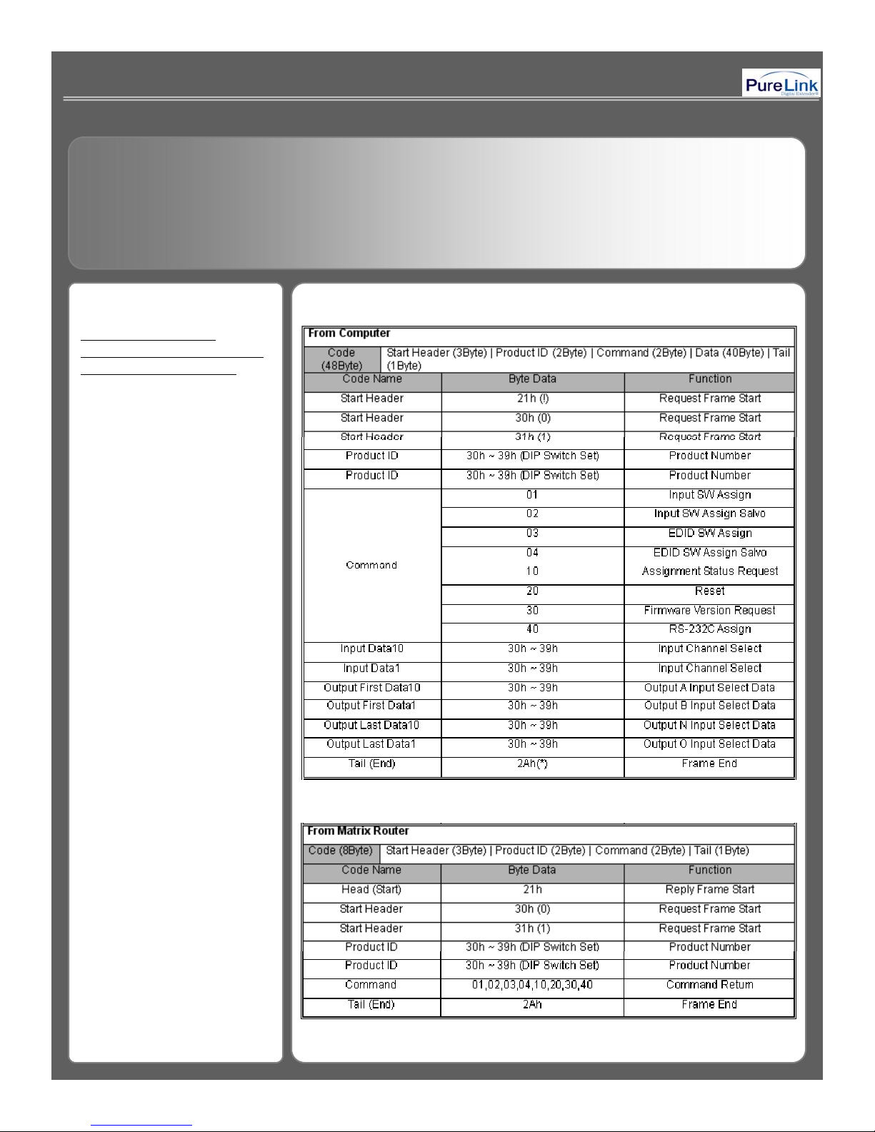
4. 4. Communication Code ConfigurationCommunication Code Configuration
44--1.The Structure of 1.The Structure of
Command code for RSCommand code for RS--232 232
& LAN Communication & LAN Communication
29
Page 30
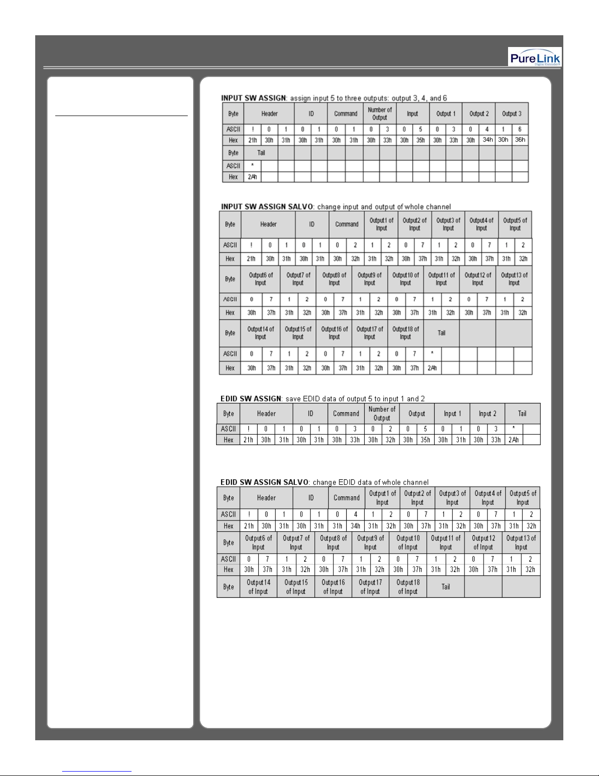
Example of Command Code.
Example of communication
code when product ID is set
to “01”.
30
Page 31
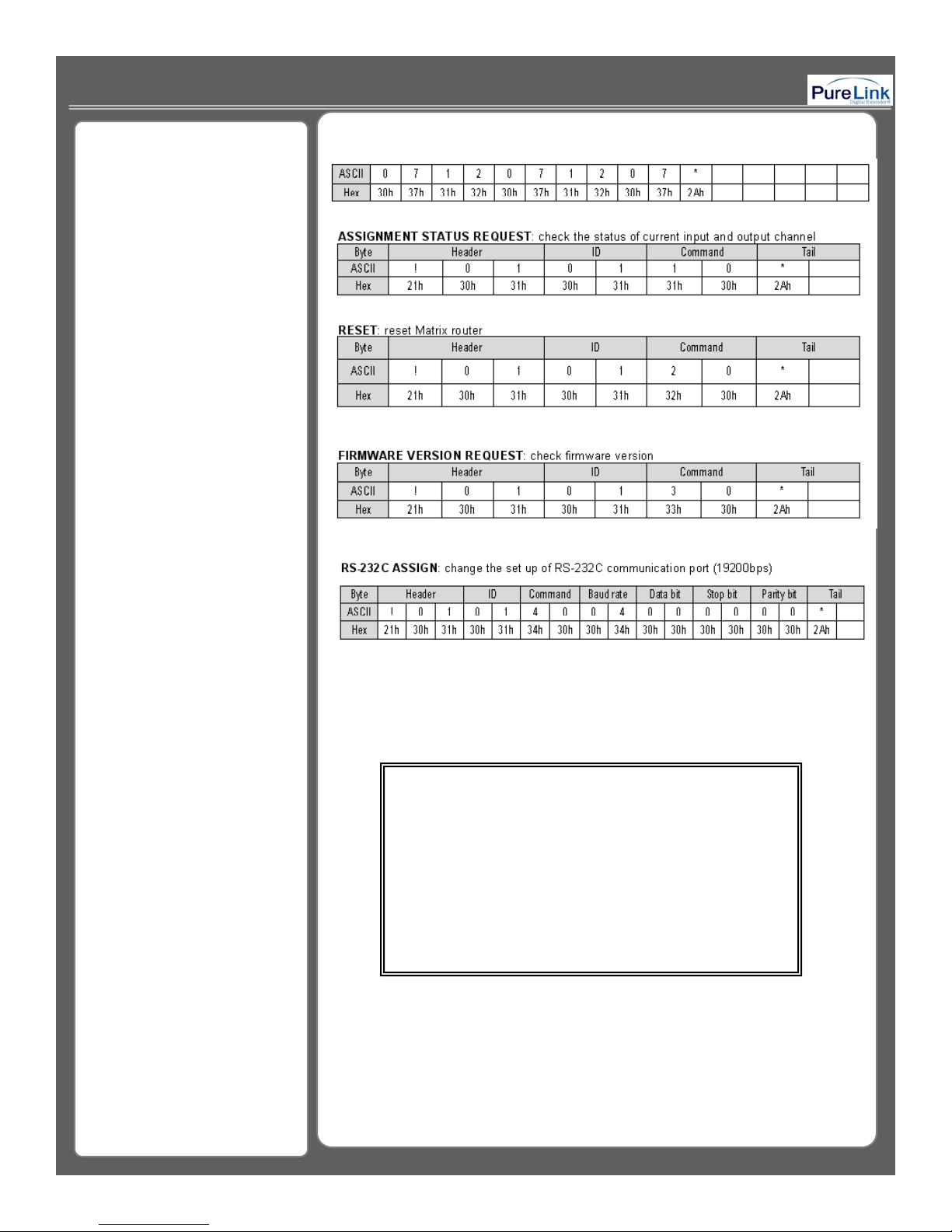
Baud rate:
bit
odd parity
code to PC control software program
“ 00 ” : 1920 bps
“ 01 ” : 4800 bps
“ 02 ” : 9600 bps
“ 03 ” : 14400 bps
“ 04 ” : 19200 bps
“ 05 ” : 28800 bps
“ 06 ” : 38400 bps
“ 07 ” : 57600 bps
“ 08 ” : 76800 bps
Data bit:
“ 00 ” : 8 bit
“
”
01 : 5
“ 02 ” : 6 bit
“ 03 ” : 7 bit
Stop bit:
“ 00 ” : 1 bit
“ 01 ” : 2 bit
Parity bit:
“ 00 ” : disable
“ 01 ” : even parity
“
”
02 :
***** Attention <RS-232C communication control> ****
If user develop own control program, please make sure to
confirm the response value after transmit the command
.
31
Page 32
44--2 LAN Communication 2 LAN Communication
11=I01&O12=I02&O13=I03&O14=I04&O15=I05&O16=I06&O17
The following data is required in order to switch channels via
internet connection
Begin with a string of LCD.CGI”,
“O 01 = I 18” represents “Output 01 Input
18”, the sequences and the size of strings
have to be identical to each other
After the reset, it needs to be connected to server again(switcher).
Channel change
http://192.168.0.2/LCD.CGI?O01=I16&O02=I18&O03=I11&O04=I12&
O05=I13&O06=I08&O07=I15&O08=I16&O09=I17&O10=I02&O
=I07&O18=I08&Submit_=SEND
Initialization (Reset)
http://192.168.0.2/LCD.CGI?O01=I16&O02=I18&O03=I11&O04=I12&
O05=I13&O06=I08&O07=I15&O08=I16&O09=I17&O10=I02&O
11=I01&O12=I02&O13=I03&O14=I04&O15=I05&O16=I06&O17
=I07&O18=I08&Submit_=Reset
32
Page 33
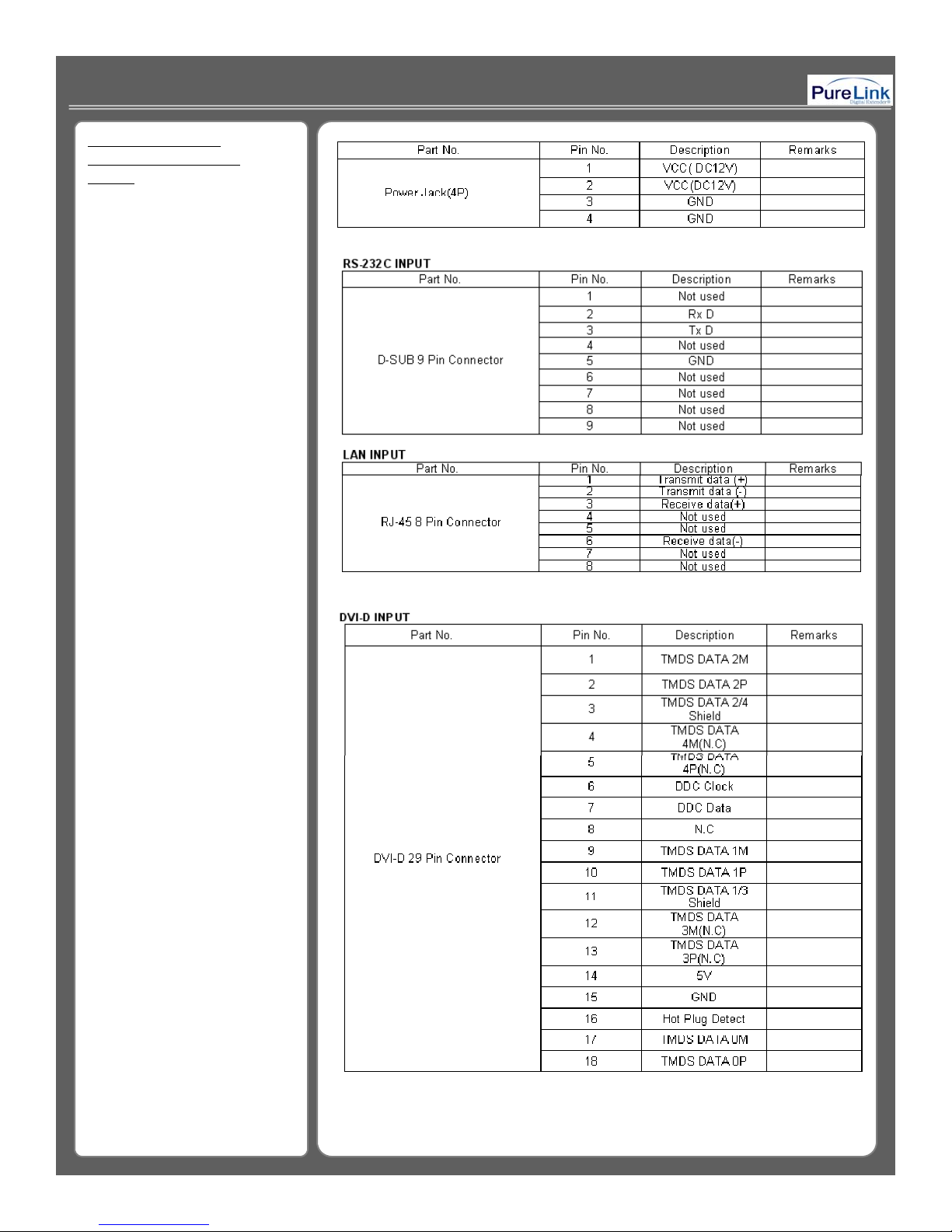
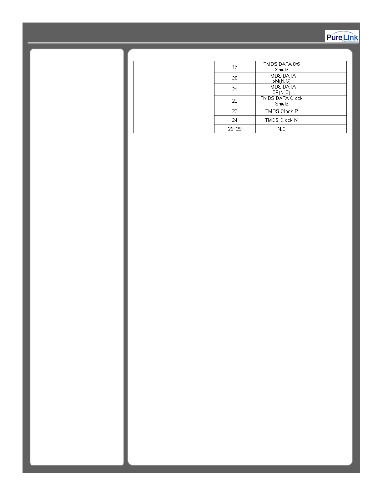
44--3 Connector Pin 3 Connector Pin
Assignment POWERAssignment POWER
INPUTINPUT
33
Page 34
34
Page 35
5. Warranty Information
y
y
deliver to customer an equivalent product or part to replace the defective item, or
the product has been damaged due to abuse, misuse, neglect, accident, unusual
▪ 2 Years Warrant
Dtrovision warrants this DVI Switcher to be free from defects in workmanship
and materials, under normal use and service, for a period of 2 yeasr from the date
of purchase from Dtrovision or its autho rize d resellers.
If a product does not work as warranted during the applicable warranty period,
Dtrovision shall, at its option and expense, repair the defective product or part,
refund to customer the purchase price paid for the defective product.
All products that are replaced will become the property of Dtrovision.
Replacement products may be new or reconditioned.
Any replaced or repaired product or part has a ninety (90) day warranty or the
reminder of the initial warranty period, whichever is longer.
Dtrovision. shall not be responsible for any software , firmware, information, or
memory data of customer contained in, stored on, or integrated with any products
returned to Dtrovision for repair under warranty or not.
▪ Warranty Limitation and Exclusion
Dtrovision shall have no further obligation under the foregoing limited warranty if
physical or electrical stress, unauthorized modifications, tampering, alterations, or
service other than by Dtrovision or its authorized agents, cause s other than from
ordinary use or failure to properly use the product in the application for which said
product is intended.
▪ RETURNS
All returns MUST have an RMA number. Please contact Dtrovision LLC or your
local dealer where you purchased the product.
Dtrovision Service Dept.
Tel: 201-488-3232, Fax: 201-621-6118. Send us email at [email protected]
© 2008 Dtrovision LLC. All Rights Reserved
35
Page 36
Dtrovision LLC.
y
yy
For help with placing an order, please contact your local distributor or
9A Bergen Turnpike
Little Ferr
, New Jersey 07643
Tel: 201-488-3232
Fax: 201-621-6118
www.dtrovision.com
reseller. For any technical question or support you need, please contact us
at [email protected]
36
 Loading...