

Page 1
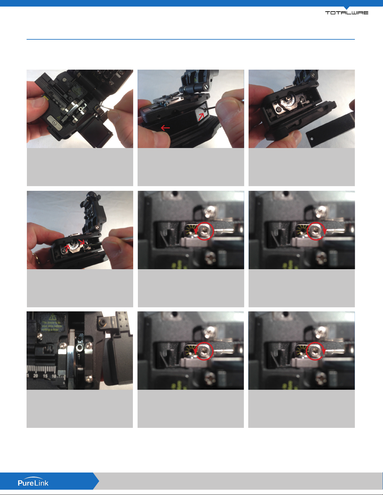
TWF2-FTT Fiber Termination Tool Adjustment Procedure
The TOTALWIRE™ TWF2 bers, with its patented integral 3M Polymer coating, is stronger and more bend insensitive than typical
glass bers. The TWF2-FTT Termination Tool comes factory adjusted to cleave TWF2 ber.
2ea M2
Using the M2 Allen wrench included with
1.
the cleaver, on the top right side remove
the screw that secures the ber scrap
box. Set the scrap box aside.
2ea T10
Loosen the two T10 guide screws with the
4.
supplied wrench. Only approx. one turn is
required, do not loosen completely.
Using the M2 Allen wrench remove the
2.
two screws that secure the guide cover.
Blade Up A
Loosen the T10 hex screw located
A.
behind the blade looking down on the
unit, counter clockwise one full turn.
Set the guide cover aside.
3.
Blade Up B
Turn the M2 Allen screw clockwise
B.
2 positions. Tighten the previously
loosened T10 hex screw and the two
T10 side guide screws clockwise until
snug.
Blade Down A
Attempt to cleave TWF2 ber. If the ber
7.
does not successfully cleave repeat Blade
UP steps A & B to increase blade height
until a successful cleave is achieved,
reassemble.
NOTE: If you are using a standard cleaver, perform the Blade UP steps listed above. To adjust your cleaver to cleave standard ber perform the
Blade DOWN adjustments listed above until the cleaver no longer cleaves standard ber, followed by the Blade UP adjustment until a successful
cleave is achieved.
All brand names, product names and trademarks are the property of their respective owners. Certain trademarks, registered trademarks, and trade names may be used to refer to
either the entities claiming the marks and names or their products. PureLink disclaims any proprietary interest in the marks and names of others. PureLink is not responsible for errors
purelinkav.com
in typography or photography. ©2016 Dtrovision LLC | PureLink
Loosen the T10 hex screw located
A.
behind the blade looking down on the
unit, counter clockwise one full turn.
Blade Down B
Turn the M2 Allen screw counter
B.
clockwise 2 positions. Rotate the
previously loosened T10 hex screw and
the two T10 side guide screws clockwise
until snug.
Page 2
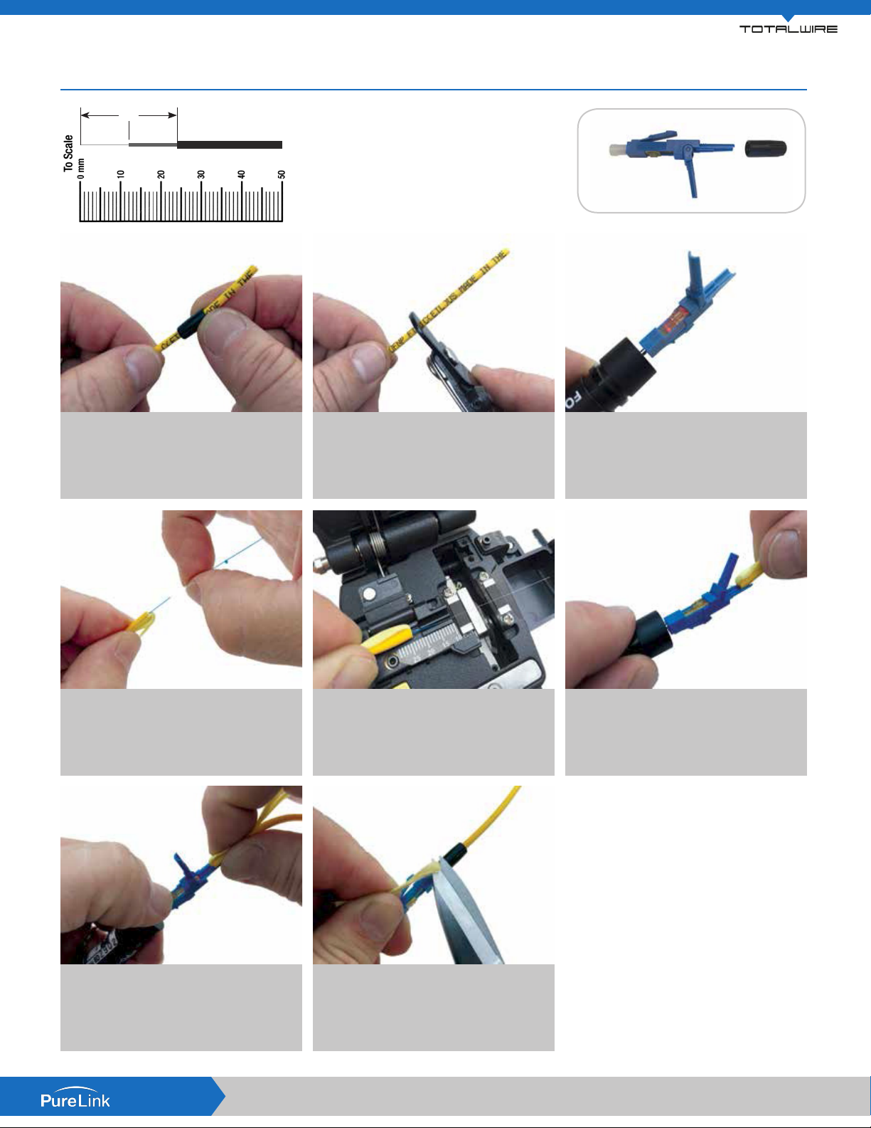
TWF2 CONNECTOR Termination Guide for: TWF2 Jacketed Fiber 2.0mm / 3.0mm
24
12 12
(A) (B) (C)
Unscrew boot from rear of connector and
1.
slide onto cable jacket. For 2.0mm slide
included build tube onto cable jacket.
*12mm Soft Peel is an approx. Do not exceed 12mm
(A) TWF2 Glass Fiber
(B) 250μm Soft Peel
(C) 2.0mm & 3.0mm Jacket
Using strippers remove approximately
2.
50mm / 2” of cable jacket.
Place onto VFL using an LC type adapter.
3.
Ensure activator slide tab is in “open”
position - slide towards rear of connector.
Open hinge on connector.
Do Not
Use Strippers
Pull Kevlar yarns back to locate TWF2
4.
ber. Use only nger tips/nails to gently
remove “Soft Peel” 250um coating to
within 12mm/1/2” of cable jacket.
Slide activator tab towards connector tip.
7.
Remove from VFL. Ensure ber is straight,
hold Kevlar to one side (2.0mm seat tube
at rear of connector). Close hinge.
Cleave ber measuring from cable jacket.
5.
For TWF2 LC = 24mm.
Install dust cap. Slide boot forward and
8.
thread one full turn to “lock in” Kevlar
strands. Cut Kevlar close to boot. Tighten
boot until secure.
Insert ber into the rear of connector until
6.
a slight “bow” is created and the light
emitting from connector window dims
and/or extinguishes.
1. TWF2 Fiber does not require the use of alcohol
cleaning as the glass ber is not exposed being
protected with TWF2 proprietary coating.
Remove the soft peel coating completely from all
sides of the ber with ngers only. Do not use
strippers.
2. Due to the extreme durability and bend
insensitivity of TWF2 ber, your cleaver may
require a wheel height adjustment procedure
to allow successful cleaving of TWF2 bers. For
more information, please refer to the TWF2-FTT
adjustment guide.
purelinkav.com
All brand names, product names and trademarks are the property of their respective owners. Certain trademarks, registered trademarks, and trade names may be used to refer to
either the entities claiming the marks and names or their products. PureLink disclaims any proprietary interest in the marks and names of others. PureLink is not responsible for errors
in typography or photography. ©2016 Dtrovision LLC | PureLink
Page 3
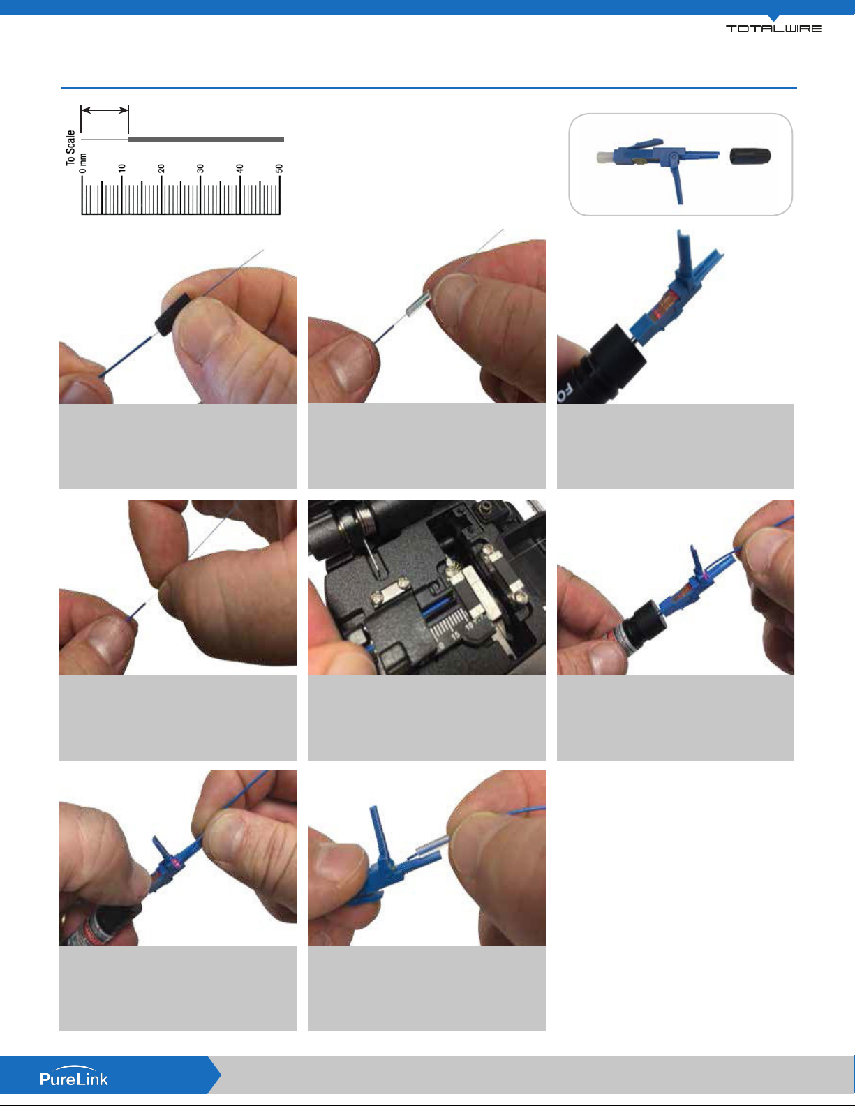
TWF2 CONNECTOR Termination Guide for: TWF2 Fiber & 900m fan out kit/tubing
12
(A) (B)
(A) TWF2 Glass Fiber
(B) 900µm Fan Tubing
Slide included 900µm build tube section
Ensure a minimum of 50mm of ber exits
1.
the fan tubing. Unscrew boot from rear of
connector and slide onto fan tubing.
2.
onto fan tubing.
Place onto VFL using an LC type adapter.
3.
Ensure activator slide tab is in “open”
postion - slide towards rear of connector.
Open hinge on connector.
Do Not
Use Strippers
Use only nger tips/nails to gently remove
4.
“Soft Peel” 250µm coating completely to
fan tubing.
Slide activator tab towards connector tip.
7.
Remove from VFL, Install dust cap.
Cleave ber measuring from fan tubing. For
5.
TWF2 LC = 12mm.
Slide build tube forward and seat in rear of
8.
connector, ensure ber is straight, close
hinge. Slide boot forward and tighten until
secure.
Insert ber into the rear of connector
6.
until a slight “bow” is created and the
light emitting from connector window
dims and/or extinguishes.
1. TWF2 Fiber does not require the use of alcohol
cleaning as the glass ber is not exposed being
protected with TWF2 proprietary coating.
Remove the soft peel coating completely from all
sides of the ber with ngers only. Do not use
strippers.
2. Due to the extreme durability and bend
insensitivity of TWF2 ber, your cleaver may
require a wheel height adjustment procedure
to allow successful cleaving of TWF2 bers. For
more information, please refer to the TWF2-FTT
adjustment guide.
purelinkav.com
All brand names, product names and trademarks are the property of their respective owners. Certain trademarks, registered trademarks, and trade names may be used to refer to
either the entities claiming the marks and names or their products. PureLink disclaims any proprietary interest in the marks and names of others. PureLink is not responsible for errors
in typography or photography. ©2016 Dtrovision LLC | PureLink
 Loading...