

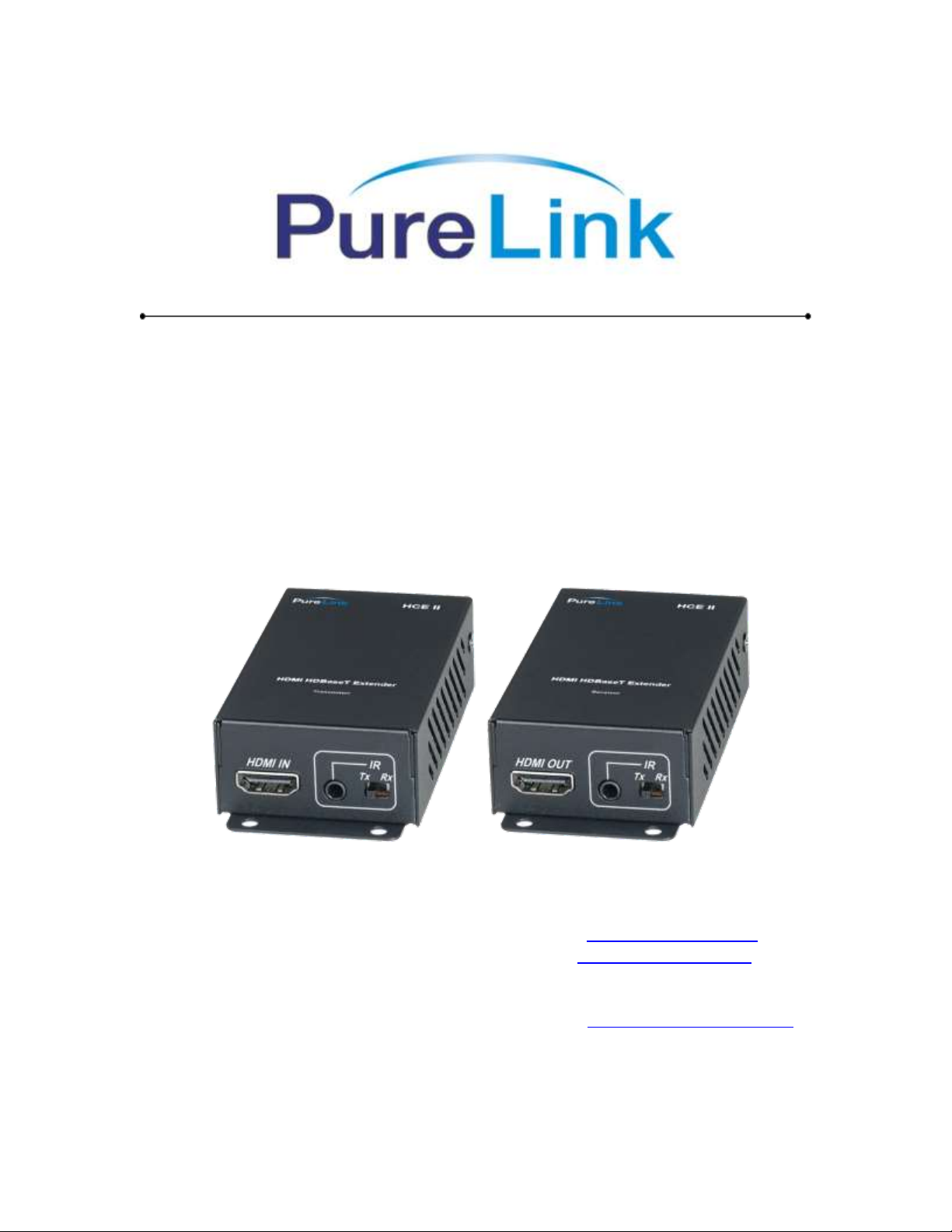
HCE II Owner’s Manual
HDMI, and IR Extender over HDBaseT
with 3D, 4K Support
PureLink
535 East Crescent Ave
Ramsey, NJ 07446
Tel: 201.488.3232
Fax: 201.621.6118
TM
Website : www.purelinkav.com
E-mail : info@purelinkav.com
For Technical Support, contact us at
: support@purelinkav.com

Package Contents
Please make sure all of the following items are included in the package:
HCE II Tx package
1 x HCE II transmitter module
1 x Power adapter
1 x IR blaster
2 x screws
1 x User manual
HCE II Rx package
1 x HCE II receiver module
1 x Power adapter
1 x IR blaster
1 x IR receiver
2 x screws
1 x User Manual
Description
The PureLink HCE II is a transmitter and receiver set for long distance extension of
HDMI video and embedded audio with bi-directional control signal (IR) over single CAT
5/6/7- type cable. It is designed on HDBaseT technology which allows full 3D support
with up to 230ft (70m) at 1080P@60Hz, and 130ft (40m) at 4K2K (UHD) resolution. A
compact and low profile enclosure makes the HCE II ideal for extending HDMI video,
embedded multi-channel audio, and bi-directional control signal to limited space
environment such as behind a flat-panel display.
PureLink HCE II is HDCP compliant and it enables the reliable, long distance extension of
HDMI signals, supporting Deep Color and full 3D and embedded HD lossless audio
formats. In addition, EDID and HDCP communication is being maintained between a
source and display. Also, the HCE II includes an IR insertion port, allowing bi-directional
control of an AV device.

PureLink by Dtrovision
Model
THE
Input Signal
HDMI
Output Signal
HDMI
Supporting Display
Resolutions
VGA ~ WUXGA (up to 1920 x 1200 @ 60Hz),
480i ~ 1080p, 4K2K @ 30Hz
Max. Distance
1920x1200 @ 60Hz or 1080P@60Hz : 230ft (70m)
4K2K@30Hz : 130ft (40m)
Connector Type
DC Power Jack
HDMI 19 Pin Female (Type A)
RJ-45
IR
Conformations
HDMI version 1.4 With HDCP
Power Rating
DC 5V , 2A
Dimension
4.01x3.34x1.02 inches / 102.1 x 85.0 x26.0 mm
Weight
0.61lbs (0.28Kg) each
Features
Zero loss & Zero noise delivery of digital high definition video and audio signal
using UTP connection, HCE II delivers HD signals over CAT5/6/7-type cables
without loss or digital interference maintaining the clarity and colors. Noise
cancellation and error correction logic enhances HDMI video and audio signals
over long distance.
Compact and Robust enclosure design allows for discreet installation behind a
flat-panel display.
Designed based on HDBaseT Technology, supporting support Deep Color and
full 3D support plus DTS-HD and Dolby TrueHD over a single low cost CATx
interface with up to 230ft (70m) at 1080P@60Hz or 1920x1200@60Hz and 130ft
(40m) at 4K2K (UHD) resolution.
Bi-directional IR control signal transmission.
Uncompressed high definition video up to 4K2K@30Hz@48bits and 3D.
Max. Data Rate- 10.2 Gbps.
HDCP (High-bandwidth Digital Content Protection) Support.
HDMI version 1.4 Support.
Audio transmission support LPCM 7.1@192KHz, Dolby TrueHD, DTS-HD MA.
3

Cable Type
Range
Pixel clock rate
Video Data Rate
Supported Video
CAT5e/CAT6
60 m
<= 225 MHz
<= 5.3 Gbps
(HD Video)
Up to 1080p, 60Hz, 36bpp (Data
rates lower than 5.3 Gbps or
below 225 MHz TMDS clock)
35 m
> 225 MHz
> 5.3 Gbps
(Ultra HD Video)
1080p 60Hz 48bpp, 1080p60Hz
3D, and 4K2K, 30Hz video
formats
CAT6a/CAT7
70 m
<= 225 MHz
<= 5.3 Gbps
(HD Video)
Up to 1080p, 60Hz, 36bpp (Data
rates lower than 5.3 Gbps or
below 225 MHz TMDS clock)
40 m
> 225 MHz
> 5.3 Gbps
(Ultra HD Video)
1080p 60Hz 48bpp, 1080p60Hz
3D, and 4K2K, 30Hz video
formats
*Please use CAT6a/CAT7 cable for maximum distance transmission.
* Travel Range Specification
PureLink by Dtrovision
4

PureLink by Dtrovision
Operation and Reliability Specification
1. Operating Environment
Temperature : 32F ~ 131F (0℃~ 55℃)
Humidity : 10% ~ 80%
Altitude : 3,000m Max.
2. Transit Environment
Temperature : -13F ~ 140F (-25℃~ 60℃)
Humidity : 5% ~ 95%
Altitude : 15,000m Max.
3. Storage Environment
Temperature : -4F ~ 185F (-20℃~ 85℃)
Humidity : 5% ~ 95%
Altitude : 3,000m Max.
4. Reliability
MTBF: 90% at over 50,000 hours aging test
In compliance with LCD Monitor reliability test standard
5

PureLink by Dtrovision
Installation and Connection Instructions
Installation and Connection Instructions
1. Turn off both the video source and the display before connecting any cables.
2. Connect CATx cable between the HCE II transmitter and the HCE II receiver.
3. Connect HDMI cable between the source and the HCE II transmitter AND the HCE
II receiver and the display.
4. Connect the power supply unit to both HCE II transmitter and receiver module.
5. Turn on Display.
6. Turn on Video Source.
6
Pin
TIA/EIA-568B
Wire color
Digital RGB
1
Orange/ White
DATA0 +
2
Orange
DATA0 -
3
Green/ White
DATA1
4
Blue
DATA2 +
5
Blue/ White
DATA2
6
Green
DATA1 -
7
Brown/ White
DATA3
8
Brown
DATA3 -
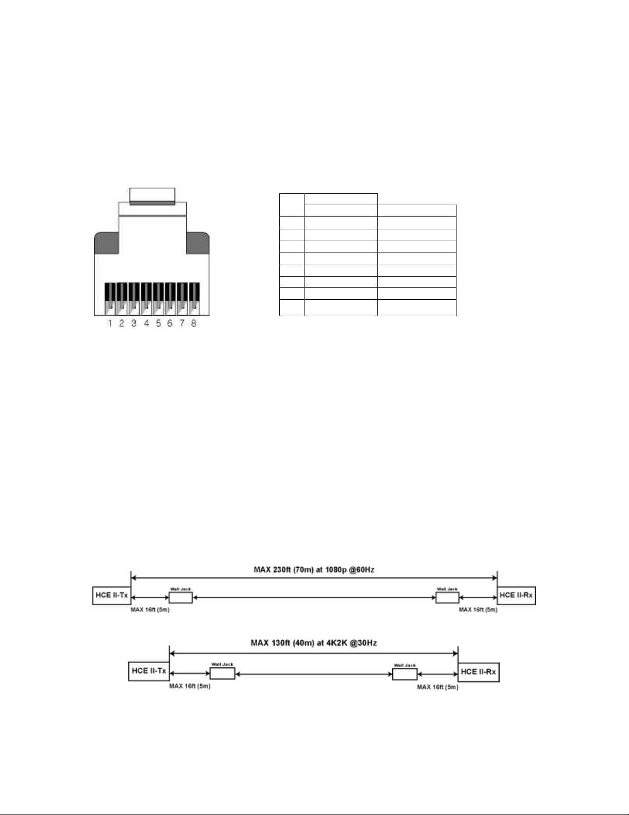
How to terminate CATx cable
HCE II was designed to conform to TIA/EIA-568-B standard. Please ensure that each PIN
layout of HCE II transmitter and HCE II receiver are corresponding with the picture
below before connecting the cable. Please note that CAT5e or above level cable enables
to deliver better video quality and longer distance.
CATx cable
Link cable recommend use high quality CAT5, CAT5e, CAT6, CAT6a, CAT7 UTP / STP or
FTP cable.
Transmission Distance
The maximum transmission distance up to 230ft (70m), use lower resolution won’t
extend longer distance
If connection through the wall socket, the cable length must less 5 meters between
HDMI extender and wall jack, as below drawing:

HCE II Transmitter and Receiver Specification
[ HCE II Transmitter ]
Module Dimensions:
1.93x3.6x0.98 ( inches) | 48.6 x 92.3 x24.8 (mm)
Connection Ports:
HDMI IN: HDMI Input
RJ-45(CAT) receptacle
5V DC Power Supply Unit Input
Green LED: Power On/Off Indication
Blue LED: IR Receive
Red LED: IR Transmit
RJ-45 Green LED: Link

[ HCE II Receiver ]
Module Dimensions:
1.93x3.6x0.98 ( inches) | 48.6 x 92.3 x24.8 (mm)
Connection Ports:
HDMI OUT: HDMI Output
RJ-45 (CAT) receptacle
5V DC Power Supply Unit Input
Green LED: Power On/Off Indication
Blue LED: IR Receive
Red LED: IR Transmit
RJ-45 Green LED: Link

IR Information
- IR Blaster is always on the end point (display)
- The unit that will be connected to the IR blaster should be on TX dip switch mode.
- The other unit with IR receiver connected should be on RX dip switch mode.
- Use the remote control of the end point device facing the IR receiver.
IR Cable Pin Assignment
[ Transmitter ]
[ Receiver ]

PureLink by Dtrovision
Technical Specification
Frequency Range: 25 ~ 165 MHz
Supporting Resolutions: Up to 4K2K / 30Hz / 48 bit
I/O Signal Standard: HDMI 1.4
Max Distance: Max 230ft (70m) at 1080P@60Hz /
Max 230ft (70m) at 1920x1200@60Hz /
Max 130ft (40m) at 4K2K@30Hz
IR Carrier: 38Khz / ±10° / 5M / 2 Way
UTP Cable specification: CAT5/5e/6/6a/7
Input Ports: HDMI Female 19P (Type A) / RJ-45
Output Ports: HDMI Female 19P (Type A) / RJ-45
Power Consumption: Transmitter: 380mA (Max) /
Receiver: 820mA (Max)
Power Rating: 5V DC / 2A
11

PureLink by Dtrovision
Warranty
Three Three (3) Years Warranty
Dtrovision warrants this HDMI, and IR Extender over HDBaseT with 3D, and 4K Support
to be free from defects in workmanship and materials, under normal use and service, for
a period of three (3) years from the date of purchase from Dtrovision or its authorized
resellers.
If a product does not work as warranted during the applicable warranty period,
Dtrovision shall, at its option and expense, repair the defective product or part, deliver
to customer an equivalent product or part to replace the defective item, or refund to
customer the purchase price paid for the defective product.
All products that are replaced will become the property of Dtrovision.
Replacement products may be new or reconditioned.
Dtrovision shall not be responsible for any software, firmware, information, or memory
data of customer contained in, stored on, or integrated with any products returned to
Dtrovision for repair under warranty or not.
Warranty Limitation and Exclusion
Dtrovision shall have no further obligation under the foregoing limited warranty if the
product has been damaged due to abuse, misuse, neglect, accident, unusual physical or
electrical stress, unauthorized modifications, tampering, alterations, or service other
than by Dtrovision or its authorized agents, causes other than from ordinary use or
failure to properly use the Product in the application for which said Product is intended.
Caution
1. The wiring must away from any equipment with electromagnetic wave, i.e.: mobile phone,
2. This device is not network equipment, do not connect with Network to avoid damage.
3. IR transmitter do not put near from receiver to avoid mutual interference.
microwave, radio equipment, fluorescent lamp, high voltage power lines.
12

PureLink by Dtrovision
FCC/CE Statement
This device complies with part 15 of FCC Rules and EN 55022/55024/61000-3 for CE
certification. Operation is subject to the following two conditions: (1) this device may
not cause harmful interference, and (2) this device must not accept any interference
received, including interference that may cause undesired operation. This equipment
has been tested and found to comply with the limits for a Class A digital device,
pursuant to part 15 and 2 of FCC Rules and EN 55022/55024/61000-3 for CE certification.
These limits are designed to provide reasonable protection against harmful interference
when the equipment is operated in a residential installation. This equipment generates,
uses, and can radiate radio frequency energy and. if not installed and used in
accordance with the instruction guide, may cause harmful interference to radio
communications. However, there is no guarantee that interference will not occur in a
particular installation. If this equipment does cause harmful interference to radio or
television reception, which can be determined by turning the equipment off and on, the
user is encouraged to try to correct the interference by one or more of the following
measures:
Re-orient or relocate the receiving antenna.
Increase the separation between the equipment and the receiver.
Connect the equipment into an outlet on a circuit different from that to which the
receiver is connected.
Consult a service representative for help.
Properly shielded and grounded cables and connectors must be used in order to comply
with FCC/CE emission limits. Changes or modifications not expressly approved by the
party responsible for compliance could void the user s authority to operate the
equipment.
13
 Loading...