

Page 1
DTS/DRS-1000RV
Owner’s Manual
DTS-1000RV: DVI/HDMI or VGA, Audio, RS-232C
Transmitter Extender
DRS-1000RV: DVI/VGA or VGA, Audio, RS-232C
Receiver Extender
Dtrovision LLC
9A Bergen Turnpike
Little Ferry, NJ 07643
Tel: 201.488.3232
Fax: 201.621.6118
www.purelinkav.com
E-mail: [email protected]
For technical support, contact: [email protected]
Page 2

Package Contents
Please make sure all of the following items are included in the package:
1) DTS-1000RV Transmitter Module or DRS-1000RV Receiver Module x 1
*The transmitter module and the receiver module are sold separately*
2) DC 12V power supply unit x 1
3) AC cord x 1
4) Owner’s Manual x 1
Page 3

General Specification
Item
Description
Model
DTS-1000RV/DRS-1000RV
Input Signal
DVI/HDMI
VGA( D-Sub)
Stereo Audio (3.5mm mini jack) x 2
RS-232
Output Signal
DVI/HDMI
VGA( D-Sub)
Stereo Audio (3.5mm mini jack) x 2
RS-232
Supporting video graphic
resolution
PC Mode : VGA ~ WUXGA
DTV Mode: 480 ~ 1920*1080P
Max. Distance
1920 x 1200 @60Hz or 1080p up to 3,300 ft
1280x1024 @ 60Hz or 1080i up to 5,000ft
Connector Configuration
DC Power Jack
DVI 29 Pin Female / D-SUB 15Pin Female
LC Fiber Connector 4 CORE / RJ-45
3.5mm STEREO Jack
RS-232C : 3 Port Phoenix connector
Conformation
DDWG DVI1.0
HDMI V1.3 HDCP
Power Consumption
DC 12V, 4.1A, 8 Watts(Max 13W)
Dimension
4.3’(W) x 5.1’(D) x 1.6’ (H) (Inch)
Weight
TX,RX 1.4 lbs per unit
DTS1000RV/DRS1000RV is a floor box-type fiber-optic extension system which is
capable of transmitting DVI/HDMI/VGA video, 3.5 stereo audio, and RS232-C
signals to remote locations (max distance up to 1000m or 0.62 miles).
DTS1000RV/DRS1000RV is equipped with readily available multimode fiber-optic
and CAT5 cables, making this system a convenient and affordable solution for
transmitting high-quality digital and analog video, as well as audio signals in
various applications.
Page 4

Operation and Reliability Specification
1. Operating Environment
Temperature : 50F ~ 104F (10℃~ 40℃)
Humidity : 10% ~ 80%
Altitude : 3,000m Max.
2. Transit Environment
Temperature : -13F ~ 140F (-25℃~ 60℃)
Humidity : 5% ~ 95%
Altitude : 15,000m Max.
3. Storage Environment
Temperature : -4F ~ -49F (-20℃~ 45℃)
Humidity : 5% ~ 95%
Altitude : 3,000m Max.
4. Reliability
MTBF: 90% at over 50,000 hours aging test
In compliance with LCD Monitor reliability test standard
Page 5

Main Features
1. High Quality Picture - No Signal Loss and Digital Noise Free
DTS-1000RV/DRS-1000RV is designed to deliver the highest quality picture
preserving the native resolutions of the digital/analog video sources, or analog
stereo audio, or RS-232 communication without any signal loss. At the same time,
the digital noises that may affect the picture quality will be eliminated. Due to
the nature of the digital signals and passing through multiple stages of
connection when using fiber optic extender, it is important to eliminate the digital
noises and boost the signal strength to preserve/enhance the video signal quality.
DTS-1000RV/DRS-1000RV equipped with Noise cancellation and error correction
logic that enhances HDMI video and audio signals over long distance.
2. Signal Amplification for signal reliability and long distance signal
transmission
12V power adapter supplies adequate power to amplify the video signal from the
video source and it also has a built-in signal repeater to support long distance.
3. Compact and durable design
DTS-1000RV/DRS-1000RV is comes in compact and robust 1RU size design.
4. Fiber optic cable for long distance signal transmission
Long Distance (Up to 5000ft at 1080i or lower signal) over cost effective multimode
fiber optic cables. (* RS-232 signal will be delivered over CAT5)
5. AUTO EDID management
The definition of AUTO EDID management is a way of saving EDID of a monitor into
EEPROM in the transmitter module before connecting to any video source. DTS-
1000RV transmitter has 14 different pre-programmed EDID data that can be
conveniently selected by end-user, if an external EDID doesn’t need to be saved.
Saving/Emulating display’s EDID in the transmitter module enhances reliability and
compatibility with various displays.
.
.6. HDCP (High-bandwidth Digital Content Protection) Compliant
Our DVI DTS-1000RV/DRS-1000RV is fully HDCP compliant. Many video sources
such as DVD players and Satellite/Cable Receivers are HDCP encrypted. For these
video sources to be displayed correctly, HDCP compliant devices (e.g., TV, DVI
Page 6
Switch, distribution amplifier) are required.
Pin
TIA/EIA-
568B
Signal
Wire color
Signal
1
Orange/ White
RS-422_TXD+
2
Orange
RS-422_TXD-
3
Green/ White
RS-422_RXD+
4
Blue
NC 5 Blue/ White
GND
6
Green
RS-422_RXD-
7
Brown/ White
NC
Installation and Connection Instructions
Installation Instruction
1. Turn off the video source and monitor before connecting any cable.
2. Connect DVI-D, VGA, Fiber, CAT5, and RS-232 cable.
3. Connect 12V DC power adapter to both transmitter and receiver module.
4. Turn on the monitor
5. Turn on the video source
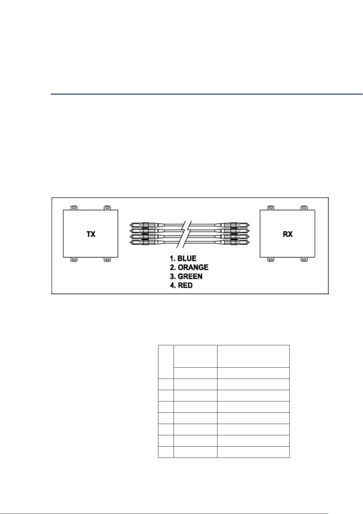
How to connect LC fiber cable between TX and RX
TX : 1 -> RX : 1 , TX : 2 -> RX : 2
TX : 3 -> RX : 3 , TX : 4 -> RX : 4
CAT5 cable
DTS-1000RV/DRS-1000RV is designed to conform to TIA/EIA-568-B standards.
Check whether the PIN MAP is properly connected to the TIA/EIA-568-B (as
illustrated below) before use. (Note: CAT-5E or CAT-6 cables will deliver signal for
longer distances).
Page 7
8
Brown
GND
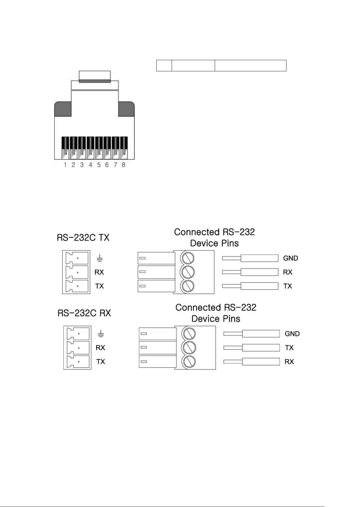
RS-232 Connection
Set up connection in the order illustrated below before use.
Page 8

PRODUCT DIMENSION
Exterior Dimension (W*D*H): 4.3’x5.1’x1.6 mm, 1.4 lbs per unit
DTS-1000RV : DVI/HDMI or VGA, Audio, RS-232C Transmitter Module
Page 9
DTS-1000RV
DVI/HDMI Fiber Optic Extension Module
Transmitter
DRS-1000RV : DVI/HDMI or VGA, Audio, RS-232C Receiver Module
Page 10
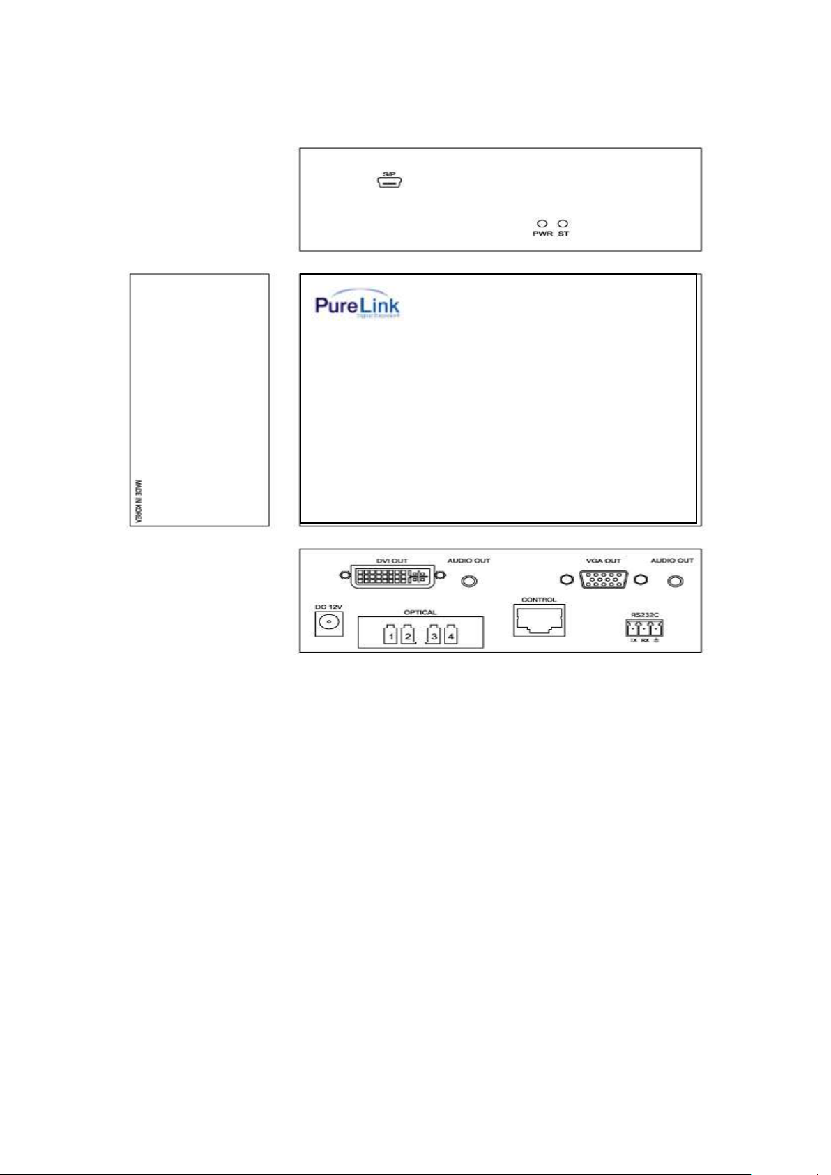
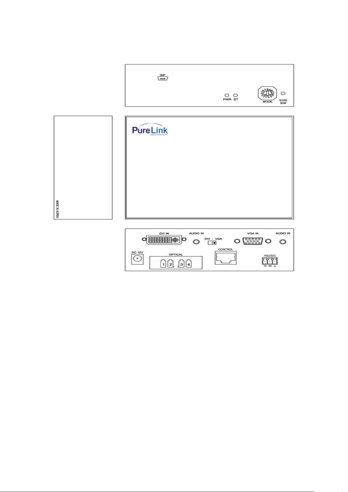
Front Panel:
DRS-1000RV
DVI/HDMI Fiber Optic Extension Module
Receiver
PWR: Power LED
ST: Signal LED
MODE: EDID Setting
EDID S/W: EDID Save button
Rear Panel:
DVI Input (Tx), DVI Output (Rx)
VGA Input (Tx), VGA Output (Rx)
DVI or VGA Dip switch (Only on Tx side)
Optical In /Out ports: Fiber optic connection
Audio In (Tx), Audio Out(Rx) :3.5mm Stereo Audio Jack
CONTROL (For RS-232): CAT5
RS232C: Phoenix Connector
DC 12V: Power Input
Page 11

USER GUIDE
Built-in Selector Switch:
It will allows user to select between DVI + Stereo Audio or VGA + Stereo Audio
signal
Internal EDID DATA
Select EDID data of your choice from the list below by adjusting MODE switch.
* MODE List
0- External EDID
1-800x600 60Hz , 2-1024x768 60Hz , 3-1280x768 60Hz ,4-1280x1024 60Hz
5-1360x768 60Hz ,6-1366x768 60Hz , 7-1400x1050 60Hz , 8-1600x900 60Hz
9-1600x1200 60Hz , A-1680x1050 60Hz ,B-1920x1200 60Hz , C-HD1080i 60Hz
D-HD1080p (2CH) , E-HD1080p(Multi)
Saving external EDID DATA:
Connect display (monitor or display) to the DTS-1000RV transmitter. Set your
rotatory switch to “ 0 “, then press the EDID S/W button. Transmitter will read and
save the EDID data on the internal EEPRom.
Page 12

Technical Specification
Data Transfer Speed: Up to 2.25 Gbps (Single Link)
Frequency Range: 25 ~ 165 MHz
Supporting Display Resolutions: Up to WUXGA (1920X1200)@60Hz / 1080p
I/O Signal Standard: Digital RGB, VGA, Stereo Audio (3.5mm), RS-232
Max Distance: 1,000m (3,300ft) at 1920x1200@60Hz / 1080p
1,500m (5,000ft) at 1600x1200@60Hz / 1080i
Optical Source: 850 nm Vcsel
Optical Cable Specification: Multimode 50/125 or, 62.5/125
Input Ports: DVI-D Female 29P / D-Sub Female 15Pins /
LC Receptacles x 4 cores / 3.5mm mini jack /
RS-232
Output Ports: DVI-D Female 29P / D-Sub Female 15Pins /
LC Receptacles x 4 cores / 3.5mm mini jack /
RS-232
Power Consumption: 8 Watts(Max 13W)
Power Rating: 12V DC / 3A
Page 13

Warranty
2 (two) Year Warranty
Dtrovision warrants this DTS-1000RV/DRS-1000RV fiber optic extender to be free
from defects in workmanship and materials, under normal use and service, for a
period of two (2) year from the date of purchase from Dtrovision or its authorized
resellers.
If a product does not work as warranted during the applicable warranty period,
Dtrovision shall, at its option and expense, repair the defective product or part,
deliver to customer an equivalent product or part to replace the defective item, or
refund to customer the purchase price paid for the defective product.
All products that are replaced will become the property of Dtrovision.
Replacement products may be new or reconditioned.
Any replaced or repaired product or part has a ninety (90) day warranty or the
reminder of the initial warranty period, whichever is longer.
Dtrovision shall not be responsible for any software, firmware, information, or
memory data of customer contained in, stored on, or integrated with any products
returned to Dtrovision for repair under warranty or not.
Warranty Limitation and Exclusion
Dtrovision shall have no further obligation under the foregoing limited warranty if
the product has been damaged due to abuse, misuse, neglect, accident, unusual
physical or electrical stress, unauthorized modifications, tampering, alterations, or
service other than by Dtrovision or its authorized agents, causes other than from
ordinary use or failure to properly use the Product in the application for which said
Product is intended.
Page 14

FCC/CE Statement
This device complies with part 15 of FCC Rules and EN 55022/55024/61000-3 for
CE certification. Operation is subject to the following two conditions: (1) this device
may not cause harmful interference, and (2) this device must not accept any
interference received, including interference that may cause undesired operation.
This equipment has been tested and found to comply with the limits for a Class A
digital device, pursuant to part 15 and 2 of FCC Rules and EN 55022/55024/61000-
3 for CE certification. These limits are designed to provide reasonable protection
against harmful interference when the equipment is operated in a residential
installation. This equipment generates, uses, and can radiate radio frequency
energy and. if not installed and used in accordance with the instruction guide, may
cause harmful interference to radio communications. However, there is no
guarantee that interference will not occur in a particular installation. If this
equipment does cause harmful interference to radio or television reception, which
can be determined by turning the equipment off and on, the user is encouraged to
try to correct the interference by one or more of the following measures:
Re-orient or relocate the receiving antenna.
Increase the separation between the equipment and the receiver.
Connect the equipment into an outlet on a circuit different from that to which
the receiver is connected.
Consult a service representative for help.
Properly shielded and grounded cables and connectors must be used in order to
comply with FCC/CE emission limits. Changes or modifications not expressly
approved by the party responsible for compliance could void the user s authority to
operate the equipment.
Page 15

UL Statement
This device has completed a UL Commercial Inspection and Testing Services for the
multimode HDMI cable complied with VW-1 under UL 758. It is validated by the UL
file number SV2038 and project number 04CA05353.
 Loading...