

Puregas PHF, PCR, PCDA, PHCA, PCME Instruction Manual
...
Instruction Manual
for PUREGAS
Compressed Air Dryers
and Adsorbers
Models: PHF
PCR
PCDA
PHCA
PCME
PMD
TOC
PUREGAS LLC
226A Commerce Street
Broomfield, CO 80020
Tel: 800-521-5351
Fax: 303-657-2205
Info@puregas.com
www.puregas.com
Made in USA P010535 Rev. E 09/11

Instruction Manual for PUREGAS
Compressed Air Dryers and Adsorbers
IMPORTANT NOTE!
This instruction manual is designed for the benefit of our customers and is intended
to assist them with the installation, operation, and maintenance of their PUREGAS
compressed air dryer or adsorber. The entire manual should be read thoroughly prior
to the installation of the unit and should be retained for future reference. Failure to do
so could result in safety issues and poor performance, and could void the warranty.
LIMITED WARRANTY AGREEMENT
All PUREGAS products carry a one-year warranty against defective workmanship
and material. This period starts with the date of shipment. PUREGAS retains the
right to address warranty claims by shipping replacement parts or by having the unit
returned to our factory for repair.
No claims for labor in replacing defective parts or for consequential damages will be
allowed. Replacement parts will be invoiced in the regular way, with invoices subject
to adjustment after the parts claimed defective are examined at our factory. No units
or parts will be accepted at our factory for warranty repairs or credit without previous
authorization from PUREGAS.
Damage incurred to the product in transit will be the responsibility of the customer,
who in turn should file a damage claim against the responsible carrier.
This warranty shall not apply to any product which has been repaired or altered in
any way by anyone other than PUREGAS, so as to affect its proper function. Neither
will this warranty apply to a product subjected to misuse, negligence, or accidental
damage.
Pressure: Do not exceed maximum operating pressure as listed on the serial label
and be sure that the system is depressurized before servicing.
Electrical: Install this product in compliance with national and local electrical codes.
Breathing Air: This product is not intended for breathing air applications, and air
treated by this equipment may not be suitable for breathing without further purification.
CAUTION!

Instruction Manual for PUREGAS
Compressed Air Dryers and Adsorbers
Table of Contents
SECTION 1 – GENERAL...........................................................................................................................................1
S
COPE OF MANUAL ....................................................................................................................................................1
NITIAL INSPECTION ...................................................................................................................................................1
I
W
ARRANTY................................................................................................................................................................1
SECTION 2 – DESCRIPTION OF OPERATION...................................................................................................1
G
ENERAL DESCRIPTION..............................................................................................................................................1
A
PPLICATIONS............................................................................................................................................................1
OPERATION OF PHF, PCDA, PHCA AND PCME MODELS.........................................................................................2
O
PERATION OF PCR MODEL ......................................................................................................................................3
OPERATION OF PMD AND TOC MODELS ...................................................................................................................4
SECTION 3 – INSTALLATION AND OPERATION.............................................................................................5
I
NSPECTION ................................................................................................................................................................5
OCATION ..................................................................................................................................................................5
L
M
OUNTING.................................................................................................................................................................5
R
ECOMMENDED INSTALLATION DIAGRAM .................................................................................................................8
IPING AND AIR CONNECTIONS ..................................................................................................................................8
P
I
NLET AND OUTLET FILTRATION ................................................................................................................................9
P
RESSURE AND FLOW CONTROL.................................................................................................................................9
INSTRUMENTATION ..................................................................................................................................................10
ELECTRICAL CONNECTIONS AND TIMER...................................................................................................................10
O
PERATING PRESSURE AND SIZING ..........................................................................................................................11
OTHER OPERATING ISSUES.......................................................................................................................................12
SECTION 4 - MAINTENANCE..............................................................................................................................13
G
ENERAL INFORMATION ..........................................................................................................................................13
ANNUAL INSPECTION ...............................................................................................................................................13
MAINTENANCE SCHEDULE .......................................................................................................................................14
SECTION 5 – REPLACEMENT PARTS...............................................................................................................15
G
ENERAL INFORMATION ..........................................................................................................................................15
SECTION 6 – TROUBLESHOOTING INFORMATION.....................................................................................21
G
ENERAL INFORMATION ..........................................................................................................................................21
TROUBLESHOOTING MATRIX....................................................................................................................................21
Figures
F
IGURE 1: OPERATION OF PHF, PCDA, PHCA AND PCME MODELS ......................................................................2
F
IGURE 2: OPERATION OF PCR MODEL......................................................................................................................3
IGURE 3: OPERATION OF PMD AND TOC MODELS..................................................................................................4
F
F
IGURE 4: DIMENSIONS OF PHF, PCDA, PHCA, AND PCME MODELS .................................................................5
F
IGURE 5: DIMENSIONS OF PCR MODEL ....................................................................................................................6
FIGURE 6: DIMENSIONS OF PMD AND TOC MODELS.................................................................................................7
F
IGURE 7: RECOMMENDED INSTALLATION DIAGRAM................................................................................................8
F
IGURE 8: WIRING DIAGRAMS...................................................................................................................................11
IGURE 9: EXPLODED VIEW OF PHF, PCDA, PHCA AND PCME MODELS............................................................15
F
F
IGURE 10: REPLACEMENT PARTS FOR PHF, PCDA, PHCA AND PCME MODELS............................................16
FIGURE 11: EXPLODED VIEW OF PCR MODEL........................................................................................................17
IGURE 12: REPLACEMENT PARTS FOR PCR MODEL..............................................................................................18
F
F
IGURE 13: EXPLODED VIEW OF PMD AND TOC MODELS .....................................................................................19
FIGURE 14: REPLACEMENT PARTS FOR PMD AND TOC MODELS..........................................................................20

SECTION 1 – GENERAL
Scope of Manual
This instruction manual is intended to assist our customers with the installation,
operation, and maintenance of their PUREGAS compressed air dryer or adsorber. The
information contained in this manual is designed to ensure a productive, trouble-free
ownership experience and should be retained for future reference.
Initial Inspection
PUREGAS products are produced in a lean manufacturing environment, where quality
assurance practices are built into all processes. Moreover, all products are thoroughly
inspected and tested prior to shipment. If shipping damage is noted, immediately
contact the responsible carrier to file a freight claim to cover the repair.
Warranty
Please read this instruction manual carefully prior to installing and operating your
PUREGAS product. Failure to follow these instructions could lead to potential safety
concerns and may void the warranty. The warranty agreement can be found on the
inside cover of this instruction manual.
SECTION 2 – DESCRIPTION OF OPERATION
General Description
PUREGAS compressed air dryers and adsorber are used to separate various elements
in compressed air using Pressure Swing Adsorption (PSA) technology. This method
employs two identical desiccant chambers, precision orifices, and solenoid valves
controlled by a solid state electronic timer.
The process is simple. The compressed air is directed through a desiccant chamber,
which contains an adsorbent material with strong affinity for moisture, CO
, and/or other
2
elements within the air stream. Once purified, the majority of the compressed air goes
directly to the application, while a portion is diverted through an orifice to regenerate the
off-line chamber. The solid state timer reverses the flow through the chambers on a
timed cycle by opening and closing the solenoid valves.
Applications
As described above, PUREGAS compressed air dryers and adsorbers are typically
used to purify a compressed air source. They may, however, be used with inert gases
(nitrogen, argon, neon, helium, and carbon dioxide), as well as other common gases
with certain restrictions. For example, oxygen requires a completely oil-free system and
hydrogen (being explosive) should be handled with explosion-proof equipment.
Page 1 of 24
A
A
Please consult the factory PRIOR to installing a unit for any application other than air
or inert gases. Use with certain liquids or gases could be harmful to the unit, result in a
combustible condition, or cause hazardous leakage. In the event of a misapplication,
the product warranty is voided and PUREGAS will assume no responsibility or liability
for any resulting loss.
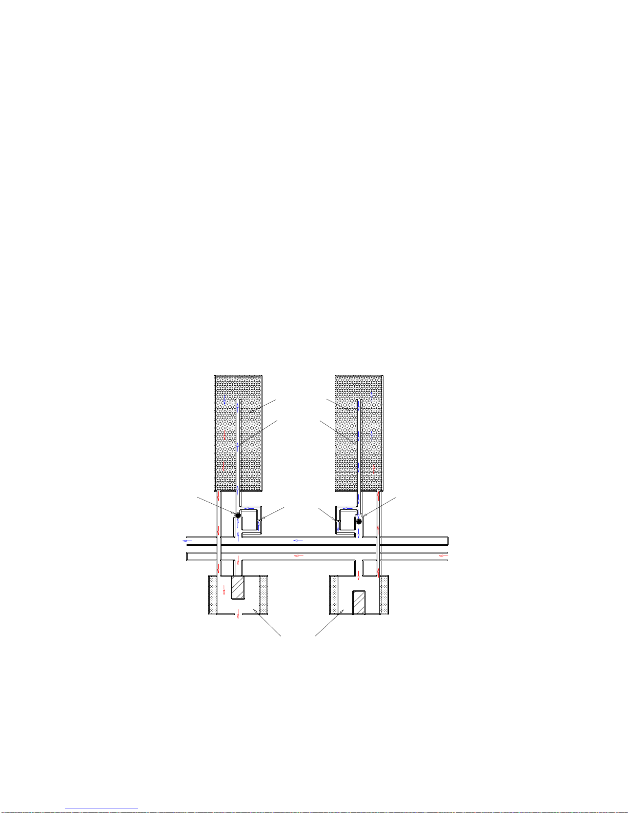
Operation of PHF, PCDA, PHCA and PCME Models
The PHF, PCDA, PHCA and PCME models utilize a common die-cast aluminum
manifold, to which the desiccant towers (chambers), 3-way solenoid valves, timer, and
other components are attached. The inlet air passes upward through the desiccant
tower immediately above the energized DC solenoid valve. When the air reaches the
top of the tower, it is redirected back down the return air tube in the center of the tower,
through the open check valve, and into the outlet passageway. Most of the air is
delivered to the application, while a portion is diverted for purging the off-line desiccant
tower. This air passes through the fixed orifice beneath the off-line tower, upward
through the air tube, and then downward through the desiccant, removing the
accumulated moisture and/or other contaminants. These unwanted elements of the gas
stream exit the unit through the purge port of the de-energized solenoid. This process is
reversed every 30 seconds to provide a continuous source of pure, ultra-dry air.
Desiccant
Tower 2
Check
Valve
(Closed)
Dry gas
Outlet
To
tmosphere
ir Tube
Orifice
3-way
Solenoid
Valve
Tower 1
Check
Valve
(Open)
Wet Gas
Inlet
FIGURE 1: OPERATION OF PHF, PCDA, PHCA AND PCME MODELS
Page 2 of 24
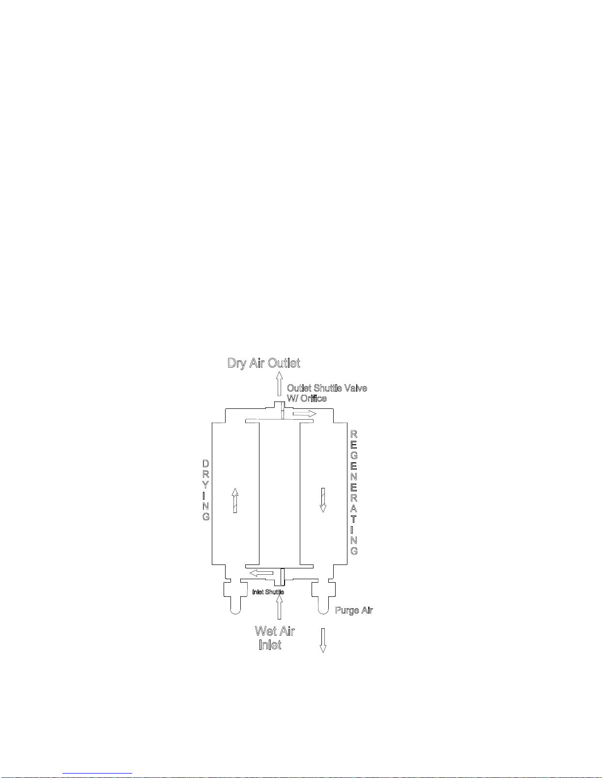
Operation of PCR Model
As previously described, the PCR model employs PSA technology to effectively remove
moisture (or other unwanted components) from a compressed air stream. It is, however,
configured differently than other PUREGAS models based on a common air manifold.
Instead of a manifold and 3-way valves to direct the airflow through the unit, the PCR
model uses shuttle valves and 2-way solenoid valves.
The inlet (lower) shuttle valve directs the compressed air flow into one of the two
desiccant chambers where nearly all of the water vapor is removed. The shuttle valve
contains an internal disk, which “shuttles” back and forth in the valve body based on the
pressure differential created by the 2-way valves (one of which is open and the other
closed).
The ultra-dry air leaving the desiccant chamber passes through the outlet shuttle valve
to the application. A precision orifice in the outlet shuttle disk, however, allows a portion
of the dry outlet flow to be redirected back through the off-line tower to purge it of the
accumulated moisture. The purge stream exits the unit through the open solenoid valve
directly below the chamber. The solid state timer controls the process by opening and
closing the solenoid valves every 60 seconds, which switches the inlet flow to the
regenerated tower.
FIGURE 2: OPERATION OF PCR MODEL
Page 3 of 24
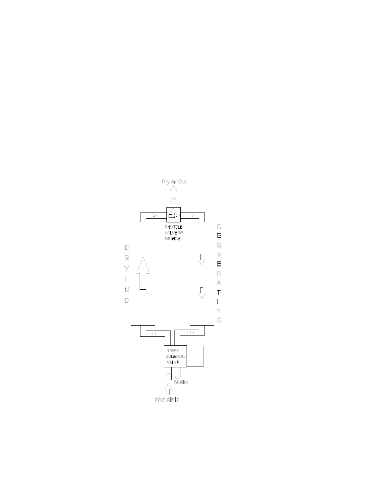
Operation of PMD and TOC Models
The PMD and TOC models also employ Pressure Swing Adsorption (PSA)
technology to remove water vapor and/or CO2 from ordinary compressed air.
These models are configured differently than the PHF or PCR models, in that
they employ a shuttle valve and 4-way valve to direct the airflow through the unit.
The 4-way valve directs the incoming air into one of the two desiccant chambers,
where the water vapor and/or CO2 are removed. Most of the purified air leaving
the desiccant chamber passes through the outlet shuttle valve to the application.
A precision orifice in the outlet shuttle disk, however, allows a portion of the
purified air to be redirected back through the off-line tower, purging it of the
accumulated moisture and CO2. The purge air exits the unit through the 4-way
valve and muffler. A solid state timer governs the process by controlling the 4way valve.
FIGURE 3: OPERATION OF PMD AND TOC MODELS
Page 4 of 24

SECTION 3 – INSTALLATION AND OPERATION
Inspection
Remove the compressed air dryer or adsorber from the shipping carton. Inspect the unit
for any visible shipping damage. If shipping damage is noted, immediately contact the
responsible carrier to file a freight claim to be reimbursed for the repair.
Location
Desiccant-type compressed air dryers and adsorbers should be installed in the coolest
practical location that is not subject to freezing temperatures. An acceptable
temperature range is between 40oF (4oC) and 125oF (52oC). Although the unit will
operate at higher temperatures, the operating life of the components will decrease at
temperatures much above 85oF (29oC). Bear in mind that abrasive dust and chemicals
will also reduce the life of any electromechanical device.
Mounting
All of the models covered by this instruction manual can be wall-mounted using the
brackets provided. Products should be mounted with the desiccant towers in a vertical
orientation for best results. Be careful to not overtighten purge mufflers.
NOTE: Dimension “A” can be 6, 9, 12, or 20,
FIGURE 4: DIMENSIONS OF PHF, PCDA, PHCA, AND PCME MODELS
depending on model. Dimensions in inches.
Page 5 of 24
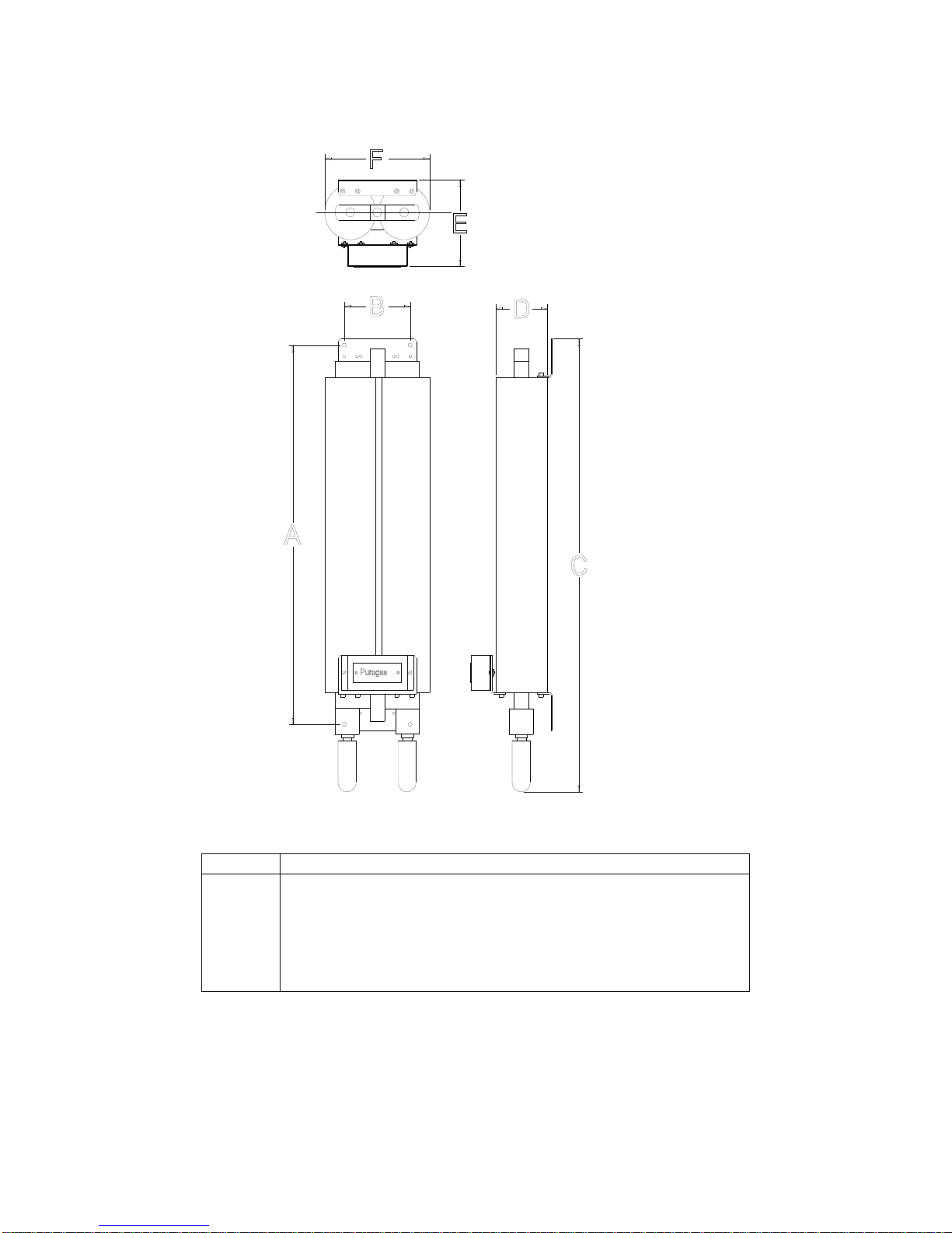
MODEL A B C D E F
PCR 15
PCR 25
PCR 50
18.625 6 25.5 3.25 5.5 8.25
22.935 6 30 4.25 6.4 9.25
28.125 6 35.25 4.25 6.4 9.25
FIGURE 5: DIMENSIONS OF PCR MODEL
Note: All dimensions are in inches.
Page 6 of 24
 Loading...