

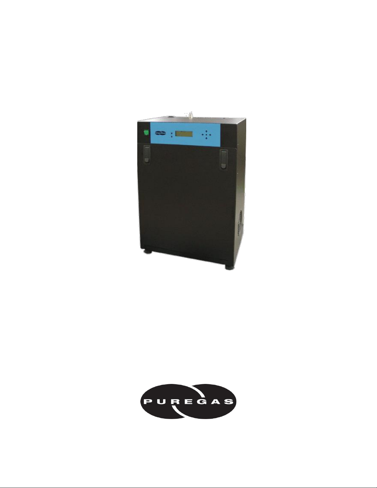
Puregas P550W Series, P550W, P550WH, P552W, P552WH User Manual
...
P011658 – Rev. P
P550W Series Air Dryers
User’s Guide
Models covered:
P550W P550WH P550WLP P552W P552WH P552WLP


PUREGAS, LLC P550W Series Air Dryers User’s Guide
Page 3 of 99 P011658 – Rev. P
1. Welcome & Congratulations
Congratulations on your purchase of a new PUREGAS P550W Series Air Dryer! We
here at PUREGAS are very proud of our products and we are committed to providing you
with the best value and service possible.
We are sure that you will be satisfied with your new air Dryer and would like to thank
you for choosing PUREGAS for your Air Dryer requirements. We also hope that you
will continue to choose us for your future air pressure and related product purchases.
For information about this and other PUREGAS products, please visit us on the web at:
www.puregas.com
2. Introduction
PLEASE READ THIS USER’S GUIDE THOROUGHLY AND SAVE FOR
FUTURE REFERENCE.
This User’s Guide is provided for the benefit of our customers and contains information
and direction specific to the PUREGAS P550W Series Air Dryers. Models covered
include P550W, P550WH, P550WLP, P552W, P552WH, and P552WLP. This guide
covers topics including: safety, specifications, installation, registration, operation, testing,
maintenance, replacement parts, service, and troubleshooting issues. Observation and
compliance with this User’s Guide will ensure the maximum life and efficiency of your
air Dryer.
This User’s Guide should be read thoroughly prior to installing, operating, or servicing
the air Dryer in order to become familiar with the recommended procedures. This will
minimize the possibility of personal injury or damage to the unit due to improper
operation or handling.

PUREGAS, LLC P550W Series Air Dryers User’s Guide
Page 4 of 99 P011658 – Rev. P
3. Table of Contents
1. Welcome & Congratulations .......................... 3
2. Introduction ..................................................... 3
3. Table of Contents ............................................. 4
4. Safety & Warning Information ...................... 6
5. Overview & Specifications .............................. 8
5.1 Product Description .................................... 8
5.2 Key Features ............................................... 8
5.3 P550W Series Air Dryer Models ................ 8
5.4 Technical Specifications ............................. 9
5.5 Dryer Function Overview ......................... 10
6. Installing Your Dryer .................................... 11
6.1 Safety & Warning Information ................. 11
6.2 Before You Begin ..................................... 12
6.3 Included Contents ..................................... 13
6.4 Required Tools and Materials ................... 13
6.5 Installation Steps ....................................... 14
6.6 Installation Checklist ................................ 23
7. Registering Your Dryer................................. 23
8. Operating Your Dryer .................................. 24
8.1 Safety & Warning Information ................. 24
8.2 Connecting Air Supply Lines to the Dryer 25
8.3 Depressurizing the Dryer .......................... 26
8.4 Powering the Dryer ON & OFF ................ 26
8.5 Using the Front Panel Display .................. 27
8.6 Identifying Dryer Alarms ......................... 29
8.7 Adjusting & Resetting Dryer Set Points ... 31
8.8 Open Panel ................................................ 39
8.9 Setting the System Pressure ...................... 39
8.10 Setting the Static Pressure ...................... 40
8.11 Setting the Outlet Pressure ...................... 40
8.12 Connecting to Common Alarm
Terminals ........................................................ 41
8.13 Connecting to Power Fail Alarm
Terminals ........................................................ 42
8.14 Connecting via Web Browser ................. 43
8.15 Using the Status Screen .......................... 45
8.16 Using the Config Screen ......................... 48
8.17 Using the Event Screen ........................... 51
8.18 Using the Alarm Screen .......................... 52
8.19 Using the Firmware Screen ..................... 53
8.20 Connecting via SNMP ............................ 55
9. Testing Your Dryer ....................................... 56
9.1 Safety & Warning Information ................. 56
9.2 Measuring Compressor Amp Draw .......... 57
9.3 Measuring Compressor Voltage ............... 58
9.4 Measuring Incoming Voltage ................... 60
9.5 Measuring Voltage from AC Step-Down
Transformer .................................................... 61
9.6 Testing Consistent Heatless Dryer
Cycling............................................................ 62
9.7 Testing Unloader Valve ............................ 64
9.8 Measuring Heatless Dryer Solenoid
Voltage............................................................ 65
9.9 Testing Air Dryer Fan ............................... 66
9.10 Testing Compressor ON/OFF Cycling ... 66
9.11 Testing High Compressor Last Run
Time Alarm ..................................................... 68
9.12 Testing Humidity Alarm and System
Shutdown ........................................................ 69
9.13 Testing High Outlet Pressure Alarm ....... 71
9.14 Testing Low Outlet Pressure Alarm........ 72
9.15 Testing Air Fittings & Hoses for Leaks .. 73
10. Maintaining Your Dryer ............................. 74
10.1 Safety & Warning Information ............... 74

PUREGAS, LLC P550W Series Air Dryers User’s Guide
Page 5 of 99 P011658 – Rev. P
10.2 Six Month Maintenance .......................... 76
10.3 8,000 Hour Maintenance ........................ 77
11. Replacement Parts & Accessories .............. 78
11.1 Dryer Parts .............................................. 78
11.2 Dryer Parts cont. ..................................... 79
11.3 Heatless Dryer Assembly Parts............... 80
11.4 Accessories for Your Dryer .................... 81
11.5 Ordering Parts from PUREGAS ............. 82
12. Service & Repair.......................................... 83
12.1 Services Offered ..................................... 83
12.2 Initiating a Service Transaction .............. 83
13. Troubleshooting Your Dryer ...................... 84
13.1 Before You Call PUREGAS ................... 84
13.2 Safety & Warning Information ............... 84
13.3 Air Dryer Won’t Power ON.................... 85
13.4 Display Screen Not Functioning ............. 86
13.5 High Outlet Pressure Alarm .................... 86
13.6 Can’t Create a High Pressure Alarm ....... 86
13.7 Low Outlet Pressure Alarm .................... 87
13.8 Can’t Create a Low Pressure Alarm ....... 87
13.9 High Humidity ........................................ 88
13.10 Can’t Create a High Humidity Alarm /
Shutdown ........................................................ 89
13.11 High Flow Rate Alarm.......................... 89
13.12 High Cabinet Temperature Alarm ........ 89
13.13 Inconsistent Heatless Dryer Cycling ..... 90
13.14 Compressor Doesn’t Operate ................ 90
13.15 Compressor Won’t Build Pressure ........ 91
13.16 Compressor Excessive AMP Draw ....... 91
13.17 High Compressor Last Run Time
Alarm .............................................................. 92
13.18 Can’t Create a High Compressor Last
Run Time Alarm ............................................. 92
13.19 Compressor Rapid ON/OFF Cycling .... 93
13.20 Contacting PUREGAS Technical
Support............................................................ 93
14. Appendix ...................................................... 94
14.1 Wiring Diagram ...................................... 94
14.2 Set Point Limits and Defaults ................. 95
14.3 SNMP Parameters ................................... 96
15. Limited Warranty Agreement .................... 97
Registration Reminder .................................... 97
16. Contacting PUREGAS ................................ 98
16.1 General .................................................... 98
16.2 Sales ........................................................ 98
16.3 Service .................................................... 98
16.4 Technical Support ................................... 98
17. Notes.............................................................. 99
PUREGAS, LLC P550W Series Air Dryers User’s Guide
Page 6 of 99 P011658 – Rev. P
4. Safety & Warning Information
This section contains general information about safety and warning points to consider and
adhere to during installation, operation, and maintenance of your air Dryer. PLEASE
READ THIS SECTION BEFORE PERFORMING ANY OPERATION OR
PROCEDURE ON YOUR AIR DRYER.
Additional warnings specific to an operation or procedure will also be presented
throughout the following sections. These will include the symbol as well as a label of
“WARNING!”, “CAUTION!”, or “IMPORTANT!”. Please be sure to pay close
attention for these warnings and read them as you encounter them.
WARNING!
For your safety, all the information in this User’s Guide must be
followed to minimize the risk of electrical shock, and prevent
property damage or personal injury.
WARNING!
Extreme care should be exercised to avoid contact with live
electrical circuits. Many procedures performed during installation,
operation, testing, and maintenance of this air Dryer require the
equipment to be running, creating a situation for potential electrical
shock. It is highly recommended that you remove all jewelry before
performing any procedures.
WARNING!
Internal surfaces may be hot. Use care when coming into contact
with internal components as there is a potential for some of these
components to become hot when in operation or standby.
PUREGAS, LLC P550W Series Air Dryers User’s Guide
Page 7 of 99 P011658 – Rev. P
CAUTION!
Depressurizing the air Dryer may be necessary before performing
certain procedures. NEVER remove pressure sensing tubes from the
Control Board without depressurizing the air Dryer first, or damage to
the Control Board will occur.
IMPORTANT!
Performing procedures not described in this User’s Guide or installing
components not supplied by PUREGAS is NOT RECOMMENDED
AND MAY VOID THE WARRANTY.
IMPORTANT!
Performing routine maintenance as outlined in the Maintaining Your
Dryer section will ensure optimal performance over the lifecycle of
your air Dryer.
CAUTION!
Incoming power to Dryer must be:
• 15 amp service recommended
• 10 amp slow blow fuse
• 110 - 125 VAC, 50/60 Hz for P550W models
• 208 - 253 VAC, 50/60 Hz, 1 Phase for P552W models
CAUTION!
Proper Installation & Maintenance as outlined in this User’s Guide is
extremely important to ensure the reliability and longevity of the
equipment as well as prevent damage or personal injury.

PUREGAS, LLC P550W Series Air Dryers User’s Guide
Page 8 of 99 P011658 – Rev. P
5. Overview & Specifications
5.1 Product Description
The P550W Series Air Dryers from PUREGAS are designed to intake wet ambient
air and remove the moisture for delivery to applications requiring a constant, ondemand source of dry, pressurized air. This process is fully automatic and will
remain consistent with minimal required periodic maintenance. These dryers are
designed specifically for indoor use.
The P550W Series Air Dryers employ a fully digital operating platform offering the
most accurate readings of Dryer variables, removable access panel allowing easier
access for adjustment and maintenance, and ultra quiet compressor with an industry
leading maintenance interval of 8,000 hours.
5.2 Key Features
• LCD display of all operating parameters
• Solid state microprocessor-based circuitry eliminates costly maintenance
• Accurate humidity sensing within 0.1% RH
• Quietest Dryer on the market - less than 50 dBA
• Oil-less compressors with 8,000 hour maintenance interval
5.3 P550W Series Air Dryer Models
Model
Description
P550W
Single Pressure Outlet, 110 - 125 VAC, 2 - 15 PSI
P550WH
4-Bank Outlet Manifold, 110 - 125 VAC, 2 - 15 PSI
P550WLP
Low Pressure, Single Pressure Outlet, 110 – 125 VAC, 0.30 – 7.50 PSI
P552W
Single Pressure Outlet, 208 - 253 VAC, 2 - 15 PSI
P552WH
4-Bank Outlet Manifold, 208 - 253 VAC, 2 - 15 PSI
P552WLP
Low Pressure, Single Pressure Outlet, 208 - 253 VAC, 0.30 – 7.50 PSI
PUREGAS, LLC P550W Series Air Dryers User’s Guide
Page 9 of 99 P011658 – Rev. P
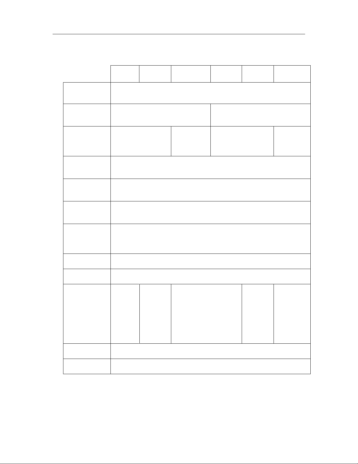
5.4 Technical Specifications
P550W
P550WH
P550WLP
P552W
P552WH
P552WLP
Output
Capacity
Normal: Up to 350 SCFD continuous
Maximum: 550 SCFD emergency
Power
Requirements
110 - 125 VAC,
50 / 60 Hz, 7.0 Amps
208 - 253 VAC, 1 Phase,
50 / 60 Hz, 3.5 Amps
Outlet
Pressure
Range
2 – 15 PSI
0.30 – 7.50
PSI
2 – 15 PSI
0.30 – 7.50
PSI
Outlet Air
Humidity
Less than 2% RH
Compressor
Type
Two-cylinder, 1/2 HP, oil-less type
Drying
Method
Heatless Desiccant
Operating
Temperature
Range
40 to 85 F (optimal)
Noise Level
51 dBA at 3’, 48 dBA at 10’
Alarms
Standard alarms – complete readings of all critical measurement points,
individual alarm indication display, including SNMP communication
Outlet
Connections
3/8”
O.D.
tube
fitting
3/8”
Press-to-
lock, 4-
bank
manifold
with shut
off
valves
3/8” O.D. tube fitting
3/8”
Press-to-
lock, 4-
bank
manifold
with shut
off
valves
3/8”
O.D.
tube
fitting
Dimensions
12” D x 17.25” W x 27” H
Net Weight
74 lbs
PUREGAS, LLC P550W Series Air Dryers User’s Guide
Page 10 of 99 P011658 – Rev. P
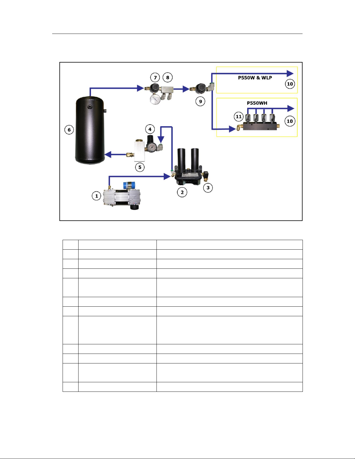
5.5 Dryer Function Overview
#
Component
Description
1
Compressor
Compresses drawn in ambient air.
2
Heatless Dryer
Removes moisture from compressed air.
3
Unloader Valve
Relieves excess Compressor head pressure.
4
Capacity Control Valve
Regulates System Pressure and prevents air from
bleeding back through the Heatless Dryer.
5
Humidity Sensor
Measures the Humidity of the compressed air.
6
Air Tank
Stores dry compressed air.
7
Static Pressure Regulator
Regulates the Static Pressure (17 PSI).
Maintains constant pressure on the Flow Block
for accurate Flow measuring.
8
Flow Block
Measures the Flow of compressed air.
9
Outlet Pressure Regulator
Regulates the Outlet Pressure.
10
Pressure Outlet
Outputs the pressure set by the Outlet Pressure
Regulator.
11
4-Bank Outlet Manifold
Distributes the air into 4 separate outlets.

PUREGAS, LLC P550W Series Air Dryers User’s Guide
Page 11 of 99 P011658 – Rev. P
6. Installing Your Dryer
6.1 Safety & Warning Information
WARNING!
Extreme care should be exercised to avoid contact with live
electrical circuits. Many procedures performed during
installation, operation, testing, and maintenance of this air Dryer
require the equipment to be running, creating a situation for
potential electrical shock. It is highly recommended that you
remove all jewelry before performing any procedures.
WARNING!
Internal surfaces may be hot. Use care when coming into contact
with internal components as there is a potential for some of these
components to become hot when in operation or standby.
CAUTION!
Proper Installation & Maintenance as outlined in this User’s Guide
is extremely important to ensure the reliability and longevity of the
equipment as well as prevent damage or personal injury.
CAUTION!
Incoming power to Dryer must be:
• 15 amp service recommended
• 10 amp slow blow fuse
• 110 - 125 VAC, 50/60 Hz for P550W models
• 208 - 253 VAC, 50/60 Hz, 1 Phase for P552W models

PUREGAS, LLC P550W Series Air Dryers User’s Guide
Page 12 of 99 P011658 – Rev. P
6.2 Before You Begin
6.2.1 Carefully inspect the unit, including the shipping box as well as the air
Dryer, for ANY DAMAGE CAUSED BY SHIPPING. If any shipping
damage is detected, it is important to file a claim with the shipping
company prior to continuing the installation procedures.
6.2.2 Read the entire Installing Your Dryer section to familiarize yourself with
the components and procedures before performing the air Dryer installation.
6.2.3 Verify the installation location of the air Dryer:
6.2.3.1 Well ventilated and free from abrasive dust or chemicals.
6.2.3.2 Ambient temperature is between 40° and 85° F (optimal).
NOTE: Higher temperatures will decrease component lifespan.
6.2.3.3 Meets the following power requirements:
• 110 - 125 VAC for P550W, P550WH and P550WLP models
• 208 - 253 VAC, 1 Phase for P552W, P552WH and P552WLP models
• All models require 50/60 Hz and minimum 15 amp service with a 10
amp slow blow fuse
6.2.4 Notify the alarm center of the installation and potential for alarms during
the process (as necessary).
IMPORTANT!
Performing procedures not described in this User’s Guide or
installing components not supplied by PUREGAS is NOT
RECOMMENDED AND MAY VOID THE WARRANTY.
PUREGAS, LLC P550W Series Air Dryers User’s Guide
Page 13 of 99 P011658 – Rev. P
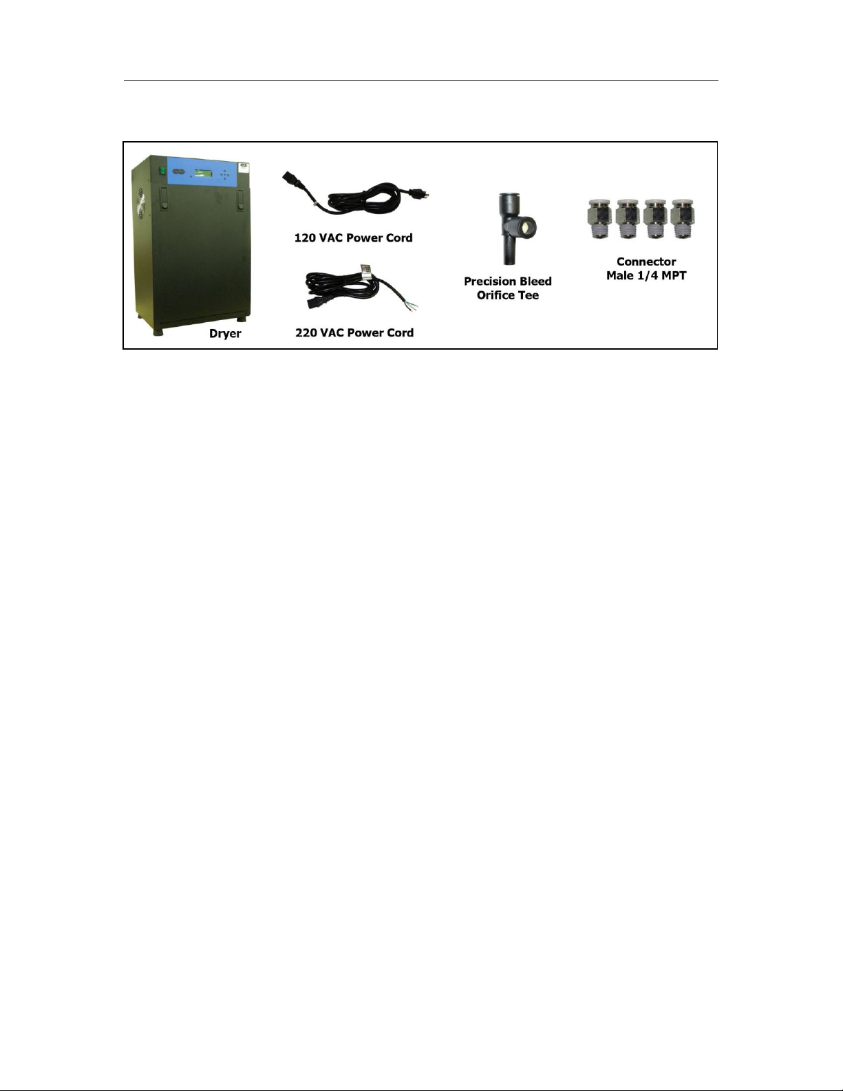
6.3 Included Contents
(1) P550W Series Air Dryer
(1) Installation Guide (not shown)
Package located inside the Dryer:
(1) 120 VAC Power Cord (P550W, P550WH, P550WLP)
(1) 220 VAC Power Cord (P552W, P552WH, P552WLP)
(4) Connector, Male 1/4 MPT (P550WH, P552WH)
(1) Tee Tube Union
(1) Precision Bleed Orifice Fitting
(1) User’s Guide (not shown)
6.4 Required Tools and Materials
• Medium adjustable wrench
• Box Cutter
• Cup of soapy water
• 1-inch paint brush
(recommended)
PUREGAS, LLC P550W Series Air Dryers User’s Guide
Page 14 of 99 P011658 – Rev. P
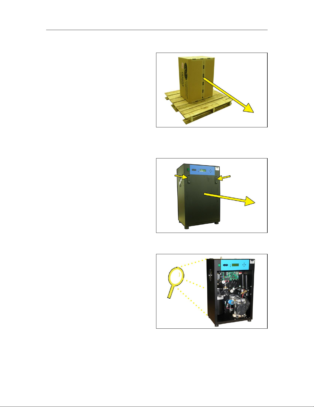
6.5 Installation Steps
6.5.1 Using a box cutter remove
the Dryer from box and all
shipping materials.
NOTE: If ANY SHIPPING
DAMAGE is detected, file a
claim with the shipping
company prior to continuing
the installation procedures.
6.5.2 Open panel latches and
remove the front panel.
6.5.3 Check for loose parts,
hoses, or wiring.
NOTE: If ANY SHIPPING
DAMAGE is detected, file a
claim with the shipping
company prior to continuing
the installation procedures.
PUREGAS, LLC P550W Series Air Dryers User’s Guide
Page 15 of 99 P011658 – Rev. P
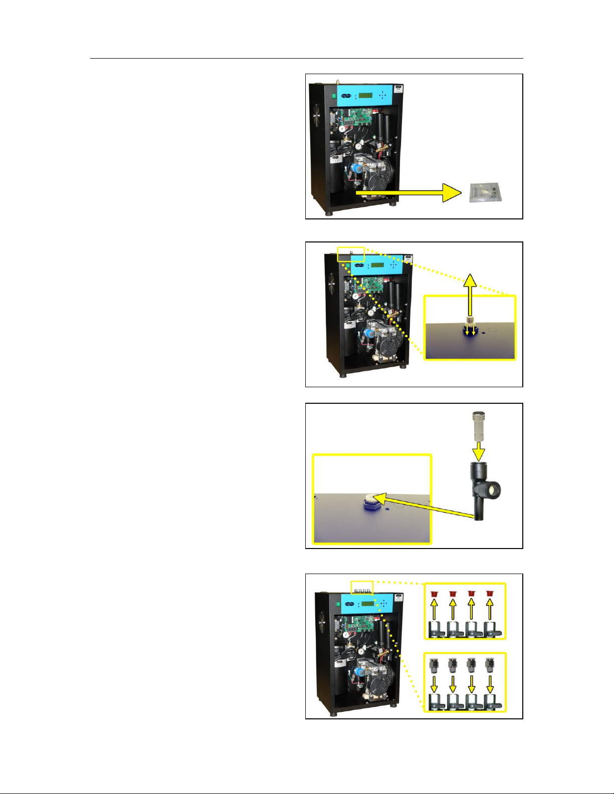
6.5.4 Remove the ship-loose
contents package.
For SINGLE Outlet dryers:
6.5.5 Remove the Plug from the
Outlet Port by pressing the
ferrule down then pulling the
plug upward.
6.5.6 Install the Plug into the
included Precision Bleed
Orifice Fitting and then into
the dryer Outlet Port.
For 4-Port Outlet dryers:
6.5.7 Remove four (4) Outlet Port
plugs.
6.5.8 Install four (4) Outlet Port
Connectors.
PUREGAS, LLC P550W Series Air Dryers User’s Guide
Page 16 of 99 P011658 – Rev. P
6.5.9 Place the Dryer at the desired operating location:
• Place the Dryer on a leveled surface
• For rack install use Universal Rack Mounting Kit P011674 (section
11.4 )
• For wall install use Wall Mounting Kit P011773 (section 11.4 )
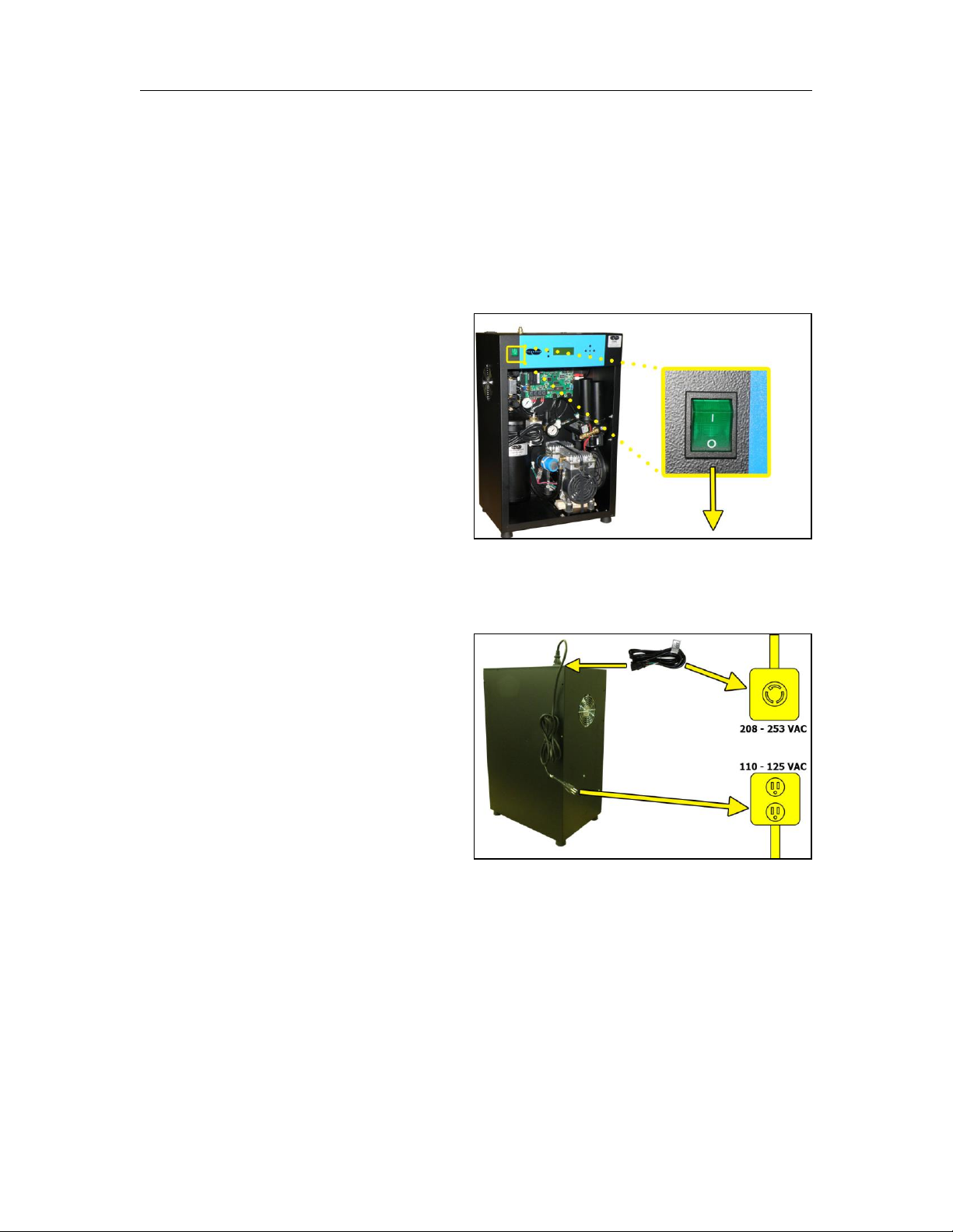
6.5.10 Verify that the Dryer is
powered OFF.
6.5.11 Plug AC Power Cord to Dryer.
6.5.12 Wire or plug the power
cord into:
• 110 - 125 VAC power
outlet for P550W,
P550WH, and
P550WLP models
• 208 - 253 VAC, 1 phase, power outlet for P552W, P552WH, and
P552WLP models.
o Line – Black (Brown)
o Neutral – White (Blue)
o Ground – Green (Green/Yellow)
PUREGAS, LLC P550W Series Air Dryers User’s Guide
Page 17 of 99 P011658 – Rev. P
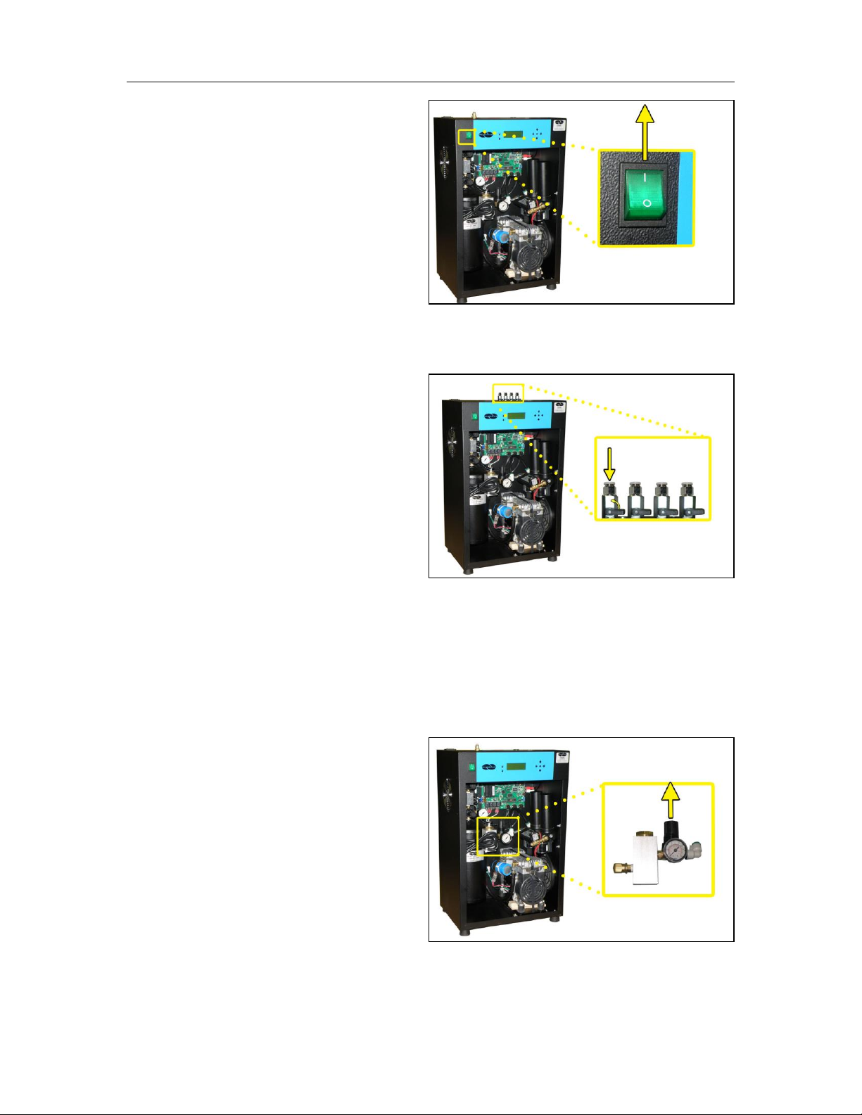
6.5.13 Power the Dryer ON.
NOTE: The compressor and
heatless Dryer will start,
creating air flow through the
Outlet Port.
For 4-Port Outlet dryers:
6.5.14 Open the first Outlet Port
slightly to create a small
amount of air flow.
6.5.15 Set the System Pressure:
With Compressor running:
6.5.15.1 Pull the Capacity
Control Valve knob out.
PUREGAS, LLC P550W Series Air Dryers User’s Guide
Page 18 of 99 P011658 – Rev. P
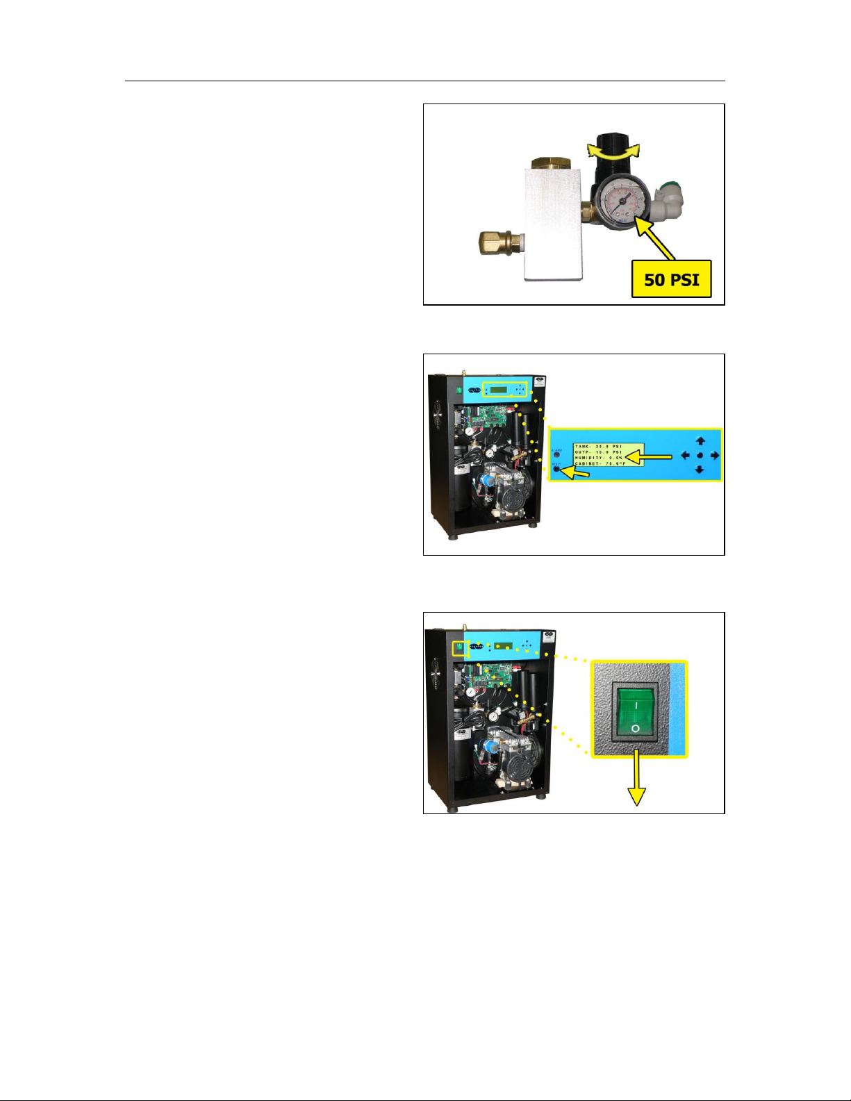
6.5.15.2 Turn the knob until
the reading on the
pressure gauge is 50
PSI.
6.5.15.3 Push the knob in to
lock.
6.5.16 Let the Dryer run until the
Humidity drops below 2%.
(may take up to 15 minutes).
NOTE: Press the RESET
button if the Dryer goes into
SHUTDOWN mode.
6.5.17 Power the Dryer OFF.
PUREGAS, LLC P550W Series Air Dryers User’s Guide
Page 19 of 99 P011658 – Rev. P
For SINGLE Outlet dryers:
6.5.18 Remove the Precision
Bleed Orifice fitting from the
Outlet Port by pressing the
ferrule down then pulling the
fitting upward.
NOTE: Save this fitting for use in
low flow applications.
6.5.19 Connect the air supply line(s):
For SINGLE Outlet dryers:
6.5.19.1 Connect a 3/8” air
supply line to the Outlet
Port.
For 4-Port Outlet dryers:
6.5.19.2 Connect up to four
(4) 3/8”air supply lines
to the Outlet Ports.
Open Outlet Ports as
required.

PUREGAS, LLC P550W Series Air Dryers User’s Guide
Page 20 of 99 P011658 – Rev. P
NOTE: For all dryers with minimal FLOW:
Install the included Precision
Bleed Orifice fitting to
maintain a constant air flow.
6.5.20 Power the Dryer ON.
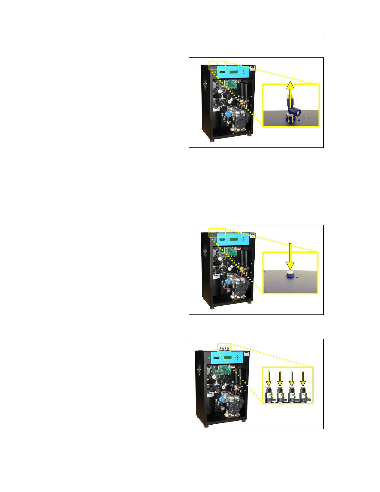
6.5.21 Set the Static Pressure:
6.5.21.1 Pull Static Pressure
Regulator knob out.
6.5.21.2 Turn knob until the
reading on the pressure
gauge is 17 PSI.
6.5.21.3 Push knob in to lock.
PUREGAS, LLC P550W Series Air Dryers User’s Guide
Page 21 of 99 P011658 – Rev. P
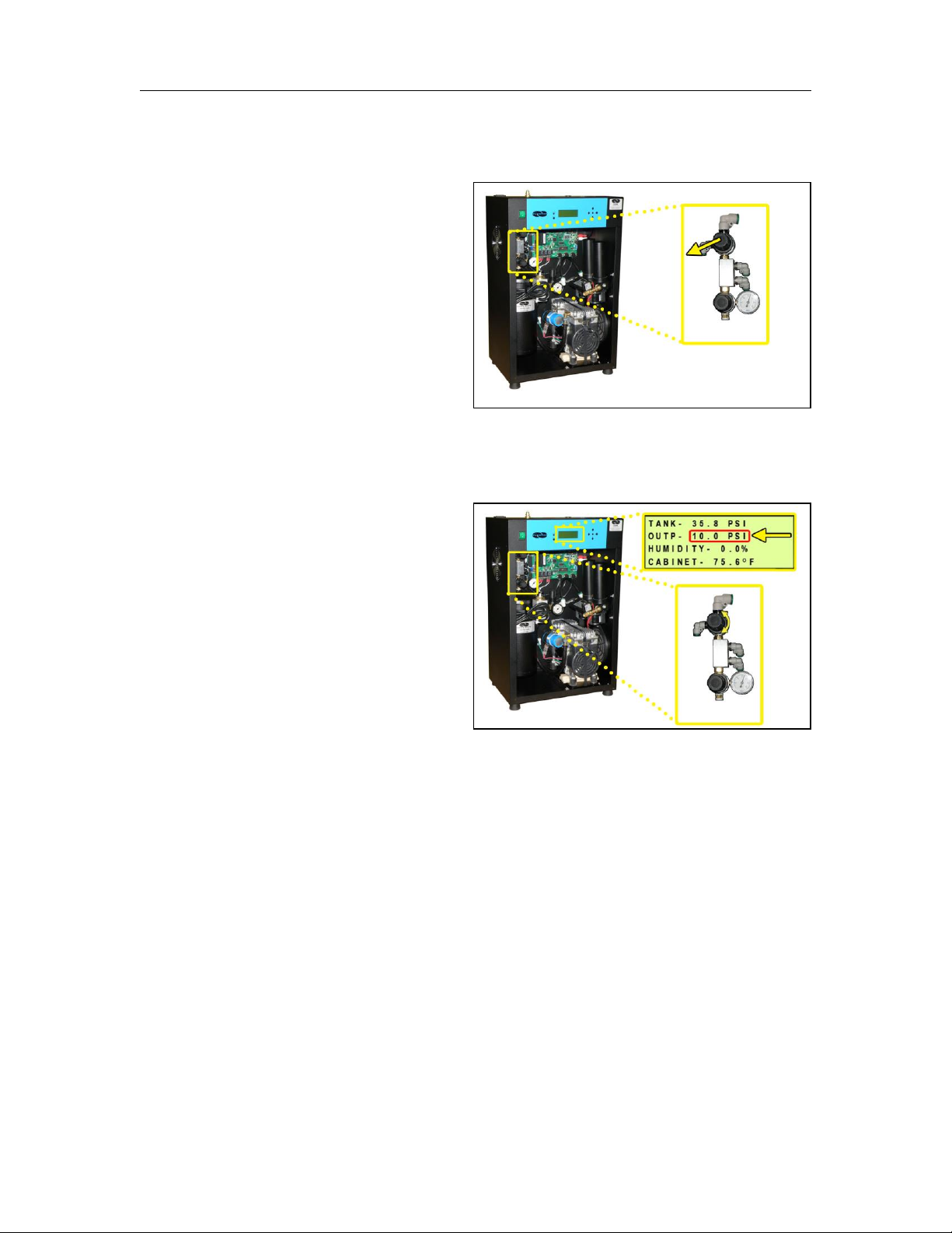
6.5.22 Set the Outlet Pressure:
6.5.22.1 Pull the Outlet
Pressure Regulator knob
out (or loosen the
retaining nut – LP
Models).
6.5.22.2 Turn knob until
Outlet Pressure (OUTP)
reading is at the desired
setting.
6.5.22.3 Push knob in to lock
(or tighten the retaining
nut – LP Models).
PUREGAS, LLC P550W Series Air Dryers User’s Guide
Page 22 of 99 P011658 – Rev. P
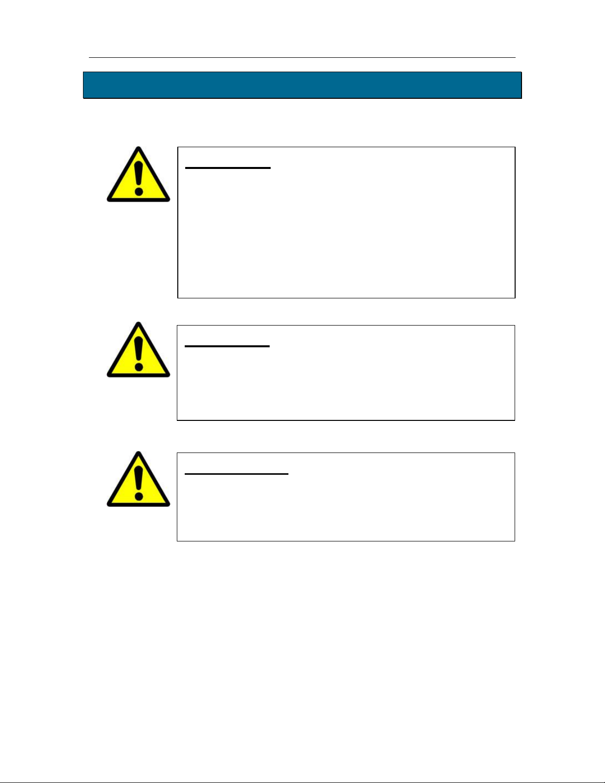
6.5.23 Check for air leaks:
NOTE: This is a general procedure that can be applied to any fitting or hose
that has air pressure in it. DO NOT SOAP TEST THE HUMIDITY
SENSOR FITTING. DAMAGE TO THE SENSOR MAY OCCUR.
With Compressor NOT running:
6.5.23.1 Listen for any ‘hissing’ sounds which may indicate a fitting or hose
air leak.
With Compressor running:
6.5.23.2 Use a 1-inch paint
brush to dab soapy water
on the air fitting or hose
connection to be tested.
If air bubbles appear at the
connection, this indicates that
air is leaking from the
connection.
If any leaks are detected, take steps to seal them off (as necessary):
• Tighten the fitting
• Re-connect the hose end
• Replace the fitting / hose / component
6.5.24 Re-install the front panel.
6.5.25 REGISTER YOUR DRYER. See section 7. for details.

PUREGAS, LLC P550W Series Air Dryers User’s Guide
Page 23 of 99 P011658 – Rev. P
6.6 Installation Checklist
No shipping damage was detected.
Dryer location meets the following requirements:
o Well ventilated
o Free from abrasive dust or chemicals
o Ambient temperature is between 40° and 85° F (optimal)
System Pressure is set to 50 PSI.
Static Pressure is set to 17 PSI.
No air leaks are present in the system.
No alarms are present on the Display Panel.
7. Registering Your Dryer
Please take a moment to register your PUREGAS P550W Series Air Dryer.
Registering is necessary to activate the Limited Warranty on your product. Once you
register, you are eligible to receive free technical support, as well as updates
concerning your PUREGAS products.
Register Online at www.puregas.com/registration
Or by Phone 1-800-521-5351 (option 2)
Have the following information available:
Model #: Serial #:
Company Name: Location Name:
Shipping Address:
City: State: Zip Code:
Contact Name: Phone #: ( ) - ext.
Email:
PUREGAS, LLC P550W Series Air Dryers User’s Guide
Page 24 of 99 P011658 – Rev. P
8. Operating Your Dryer
8.1 Safety & Warning Information
WARNING!
Extreme care should be exercised to avoid contact with live
electrical circuits. Many procedures performed during
installation, operation, testing, and maintenance of this air Dryer
require the equipment to be running, creating a situation for
potential electrical shock. It is highly recommended that you
remove all jewelry before performing any procedures.
WARNING!
Internal surfaces may be hot. Use care when coming into contact
with internal components as there is a potential for some of these
components to become hot when in operation or standby.
IMPORTANT!
Performing procedures not described in this User’s Guide or
installing components not supplied by PUREGAS is NOT
RECOMMENDED AND MAY VOID THE WARRANTY.
PUREGAS, LLC P550W Series Air Dryers User’s Guide
Page 25 of 99 P011658 – Rev. P
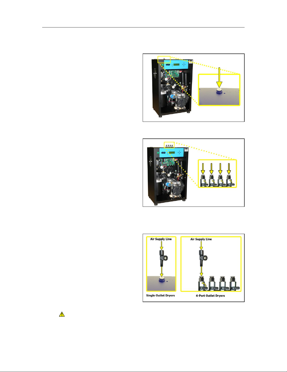
8.2 Connecting Air Supply Lines to the Dryer
For SINGLE Outlet dryers:
8.2.1 Connect a 3/8” air supply
line to the Outlet Port.
For 4-Port Outlet dryers:
8.2.2 Connect up to four (4)
3/8”air supply lines to the
Outlet Ports.
Open Outlet Ports as
required.
NOTE: For all dryers with minimal flow:
Install the included Precision
Bleed Orifice fitting to
maintain a constant air flow.
CAUTION: Be careful when removing outlet plugs or connected Air Supply
Lines. System may be pressurized.
PUREGAS, LLC P550W Series Air Dryers User’s Guide
Page 26 of 99 P011658 – Rev. P
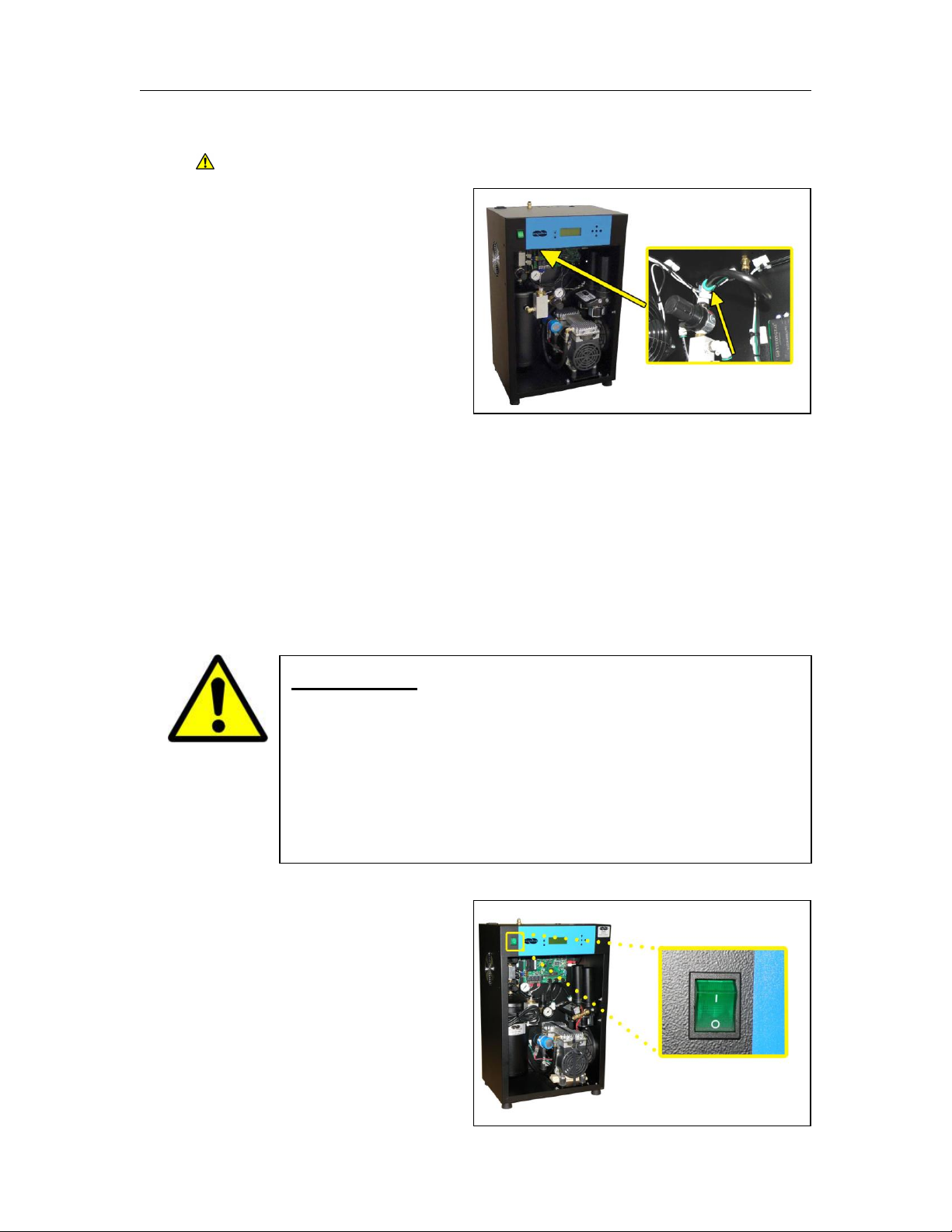
8.3 Depressurizing the Dryer
CAUTION: Be careful when removing air hose. System is pressurized.
8.3.1 Disconnect air hose from
the quick disconnect
connector located on top of
Outlet Pressure Regulator.
8.3.2 To prevent pressure from building back up, power the Dryer OFF (See
section 8.4 ).
8.3.3 Reconnect air hose.
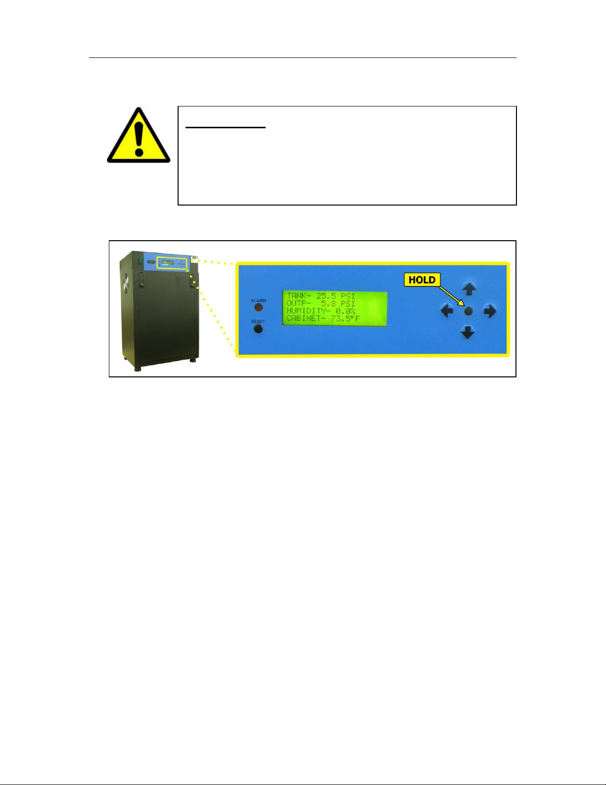
8.4 Powering the Dryer ON & OFF
8.4.1 POWER Switch - Controls
the main power to the Dryer.
CAUTION!
Incoming power to Dryer must be:
• 15 amp service recommended
• 10 amp slow blow fuse
• 110 - 125 VAC, 50/60 Hz for P550W models
• 208 - 253 VAC, 50/60 Hz, 1 Phase for P552W models
PUREGAS, LLC P550W Series Air Dryers User’s Guide
Page 27 of 99 P011658 – Rev. P
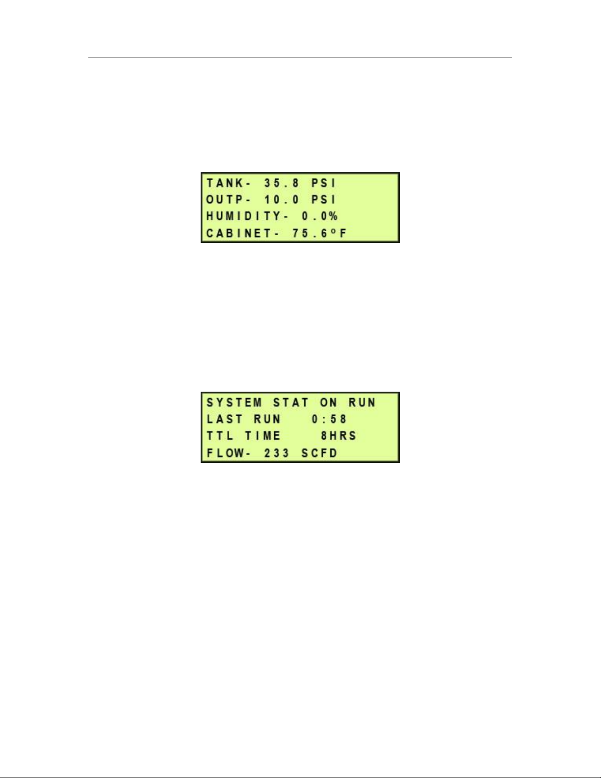
8.5 Using the Front Panel Display
8.5.1 ALARM LED – Indicates an alarm is present.
8.5.2 RESET Button – Clears an alarm and allows the system to continue
operating.
8.5.3 HOLD Button – Freezes the current information screen on the display.
When pressed again, it will allow the information screens to begin cycling
again.
8.5.4 Arrow Buttons – Used to access, navigate, and change values in the Set
Point Adjust screens.
CAUTION!
The Display Screen is covered by a clear protective layer that
guards against Electrostatic Discharge (ESD). DO NOT REMOVE
THIS LAYER.
PUREGAS, LLC P550W Series Air Dryers User’s Guide
Page 28 of 99 P011658 – Rev. P
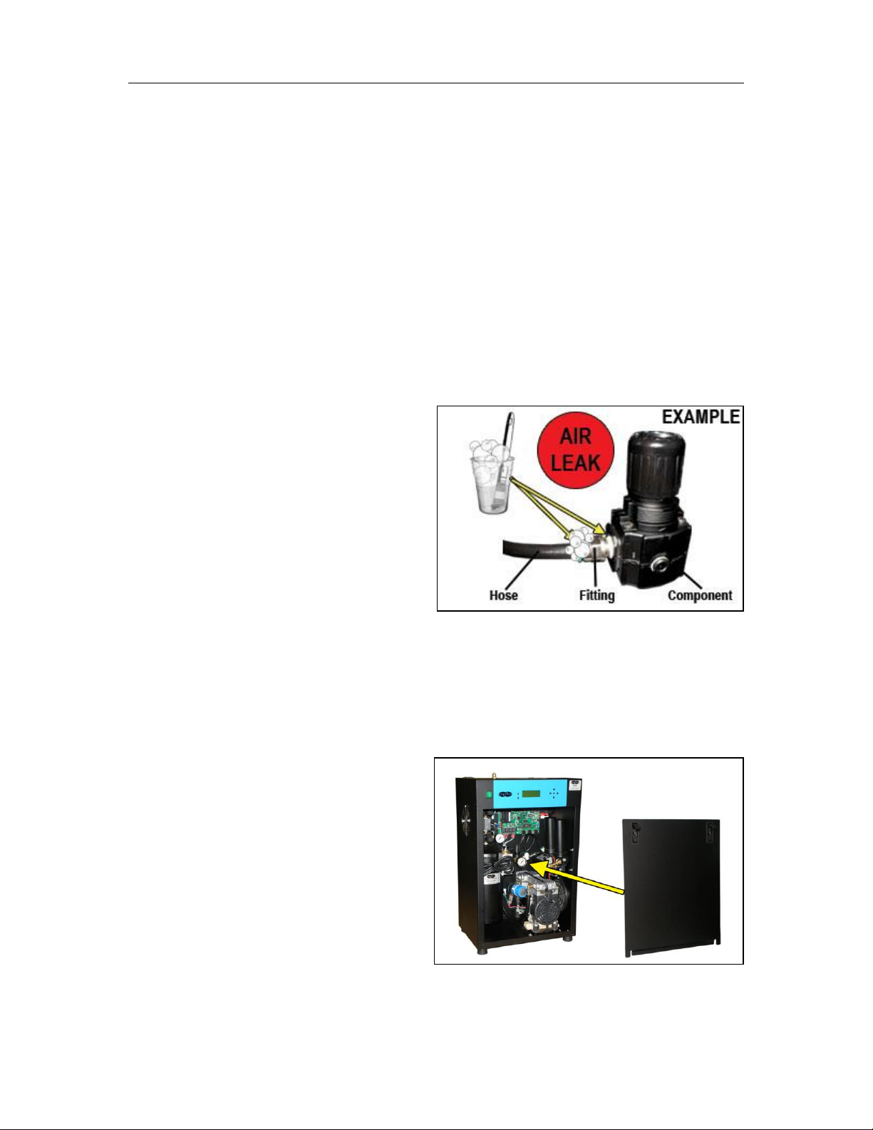
8.5.5 Display Screen - Shows the current Dryer readings. Will cycle between
the following information screens (unless the HOLD button has been
pressed):
8.5.5.1 Tank Screen
TANK – Air Tank pressure - fluctuates between 20 – 50 PSI.
OUTP – Outlet Pressure regulated by the Outlet Pressure Regulator
HUMIDITY – Humidity level of the system.
CABINET – Temperature of the Dryer cabinet compartment.
8.5.5.2 System Stat Screen
SYSTEM STAT - Running Status of the system:
• ON RUN – System is Online.
• SHUTDOWN – System has been shutdown as a result of either a
Humidity or High Cabinet Temperature alarm.
LAST RUN – How many minutes the compressor ran during the last Air
Tank pressurization cycle.
TTL TIME – How many hours the compressor has run since the last
Comp Run Reset.
FLOW – Air Flow Rate
PUREGAS, LLC P550W Series Air Dryers User’s Guide
Page 29 of 99 P011658 – Rev. P
8.6 Identifying Dryer Alarms
8.6.1 High Outlet Pressure Alarm -
Occurs when the Outlet Pressure
(OUTP) rises above the alarm
set point for more than one (1)
minute.
(Default setting is 10.0 PSI for Standard models / 7.50 PSI for LP models)
See section 13.5 for troubleshooting information.
8.6.2 Low Outlet Pressure Alarm –
Occurs when the Outlet Pressure
(OUTP) drops below the alarm
set point for more than one (1)
minute.
(Default setting is 2.0 PSI for Standard models / 0.30 PSI for LP models)
See section 13.7 for troubleshooting information.
8.6.3 High Humidity Alarm –
Occurs when the Humidity level
rises above the alarm set point
for more than one (1) minute.
(Default setting is 10.0%)
If this alarm is present for one (1) minute or more, the air Dryer will go into
SHUTDOWN mode to prevent saturated air from being delivered to the
supply line.
See section 13.9 for troubleshooting information.

PUREGAS, LLC P550W Series Air Dryers User’s Guide
Page 30 of 99 P011658 – Rev. P
8.6.4 High Cabinet Temperature Alarm -
Occurs when the temperature in
the cabinet rises above 120°F for
more than ten (10) seconds.
If this alarm is present for three (3) minutes or more, the Compressor will
SHUTDOWN to protect against damage due to overheating. Once the
temperature lowers to 112°F the Compressor will re-start.
See section 13.12 for troubleshooting information.
8.6.5 High Compressor Last Run Time Alarm –
Occurs when the compressor
takes longer to pressurize the air
tank than the set point for the
alarm. (Default setting is 3:00
minutes)
See section 13.17 for troubleshooting information.
8.6.6 Compressor Total Hour Alarm –
Occurs when the compressor has
reached an 8,000 hour
maintenance interval. Perform
the required maintenance.
See section 10.3 for maintenance information.
8.6.7 High Flow Rate Alarm –
Occurs when the Flow Rate
(FLOW) rises above the alarm
set point for more than one (1)
minute. (Default setting is 500 SCFD)
See section 13.11 for troubleshooting information.
 Loading...