

P200W2 Series Dehydrator
User’s Guide
Models covered:
P200W2 P208W2 P200WA2
P012213 – Rev. F


PUREGAS, LLC P200W2 Series Dehydrator User’s Guide
1. Welcome & Congratulations
Congratulations on your purchase of a new PUREGAS P200W2 Series Dehydrator! We
here at PUREGAS are very proud of our products and we are committed to providing you
with the best value and service possible.
We are sure that you will be satisfied with your new Dehydrator and would like to thank
you for choosing PUREGAS for your Dehydrator requirements. We also hope that you
will continue to choose us for your future air pressure and related product purchases.
For information about this and other PUREGAS products, please visit us on the web at:
www.puregas.com
2. Introduction
PLEASE READ THIS USER’S GUIDE THOROUGHLY AND SAVE FOR
FUTURE REFERENCE.
This User’s Guide is provided for the benefit of our customers and contains information
and direction specific to the PUREGAS P200W2 Series Dehydrator. Models covered
include P200W2, P208W2, and P200WA2. This guide will cover topics including:
safety, specifications, installation, registration, operation, testing, service, and
troubleshooting issues. Observation and compliance with this User’s Guide will ensure
the maximum life and efficiency of your Dehydrator.
This User’s Guide should be read thoroughly prior to installing or operating the
Dehydrator in order to become familiar with the recommended procedures. This will
minimize the possibility of personal injury or damage to the unit due to improper
operation or handling.
Page 3 of 82 P012213 – Rev. F

PUREGAS, LLC P200W2 Series Dehydrator User’s Guide
3. Table of Contents
8.13 Using the Status Screen .......................... 52
1. Welcome & Congratulations .......................... 3
8.14 Using the Setup Screen ........................... 54
2. Introduction ..................................................... 3
3. Table of Contents ............................................. 4
4. Safety & Warning Information ...................... 6
5. Overview & Specifications .............................. 8
5.1 Product Description .................................... 8
5.2 Key Features ............................................... 8
5.3 P200W2 Series Dehydrator Models ........... 9
5.4 Technical Specifications ............................. 9
6. Installing Your Dehydrator .......................... 10
6.1 Safety & Warning Information ................. 10
6.2 Before You Begin ..................................... 11
6.3 Included Contents ..................................... 12
6.4 Required Tools and Materials ................... 12
6.5 Installation Steps ....................................... 13
6.6 Installation Checklist ................................ 27
7. Registering Your Dehydrator ....................... 28
8.15 Using the Event Screen ........................... 57
8.16 Using the Alarm Screen .......................... 58
8.17 Using the Firmware Screen ..................... 59
8.18 Connecting via SNMP ............................ 61
9. Testing Your Dehydrator .............................. 62
9.1 Safety & Warning Information ................. 62
9.2 Measuring Incoming Voltage ................... 63
9.3 Testing High Pressure Alarm .................... 65
9.4 Testing Low Pressure Alarm .................... 66
9.5 Testing High Duty Cycle Alarm ............... 67
10. Service & Repair .......................................... 69
10.1 Services Offered ..................................... 69
10.2 Initiating a Service Transaction .............. 69
11. Troubleshooting Your Dehydrator ............ 70
11.1 Before You Call PUREGAS ................... 70
11.2 Safety & Warning Information ............... 70
11.3 Dehydrator Won’t Power ON ................. 72
11.4 Display Screen Not Functioning ............. 72
8. Operating Your Dehydrator ......................... 29
11.5 High Pressure Alarm ............................... 72
11.6 Can’t Create a High Pressure Alarm ....... 73
8.1 Safety & Warning Information ................. 29
11.7 Low Pressure Alarm ............................... 73
8.2 Connecting an Air Supply Line ................ 30
11.8 Can’t Create a Low Pressure Alarm ....... 74
8.3 Powering the Dehydrator ON & OFF ....... 31
11.9 High Humidity ........................................ 74
8.4 Using the Front Panel Display .................. 32
11.10 High Cabinet Temperature Alarm......... 74
8.5 Identifying Dehydrator Alarms ................. 34
11.11 Low Cabinet Temperature Alarm ......... 74
8.6 Accessing the Set Up Menu ...................... 36
11.12 Duty Cycle Alarm ................................. 75
8.7 Using the System Operations Menu ......... 37
11.13 Can’t Create a Duty Cycle Alarm ......... 75
8.8 Using the Alarm Set Points Menu ............ 39
11.14 Unable to connect via Web Browser ..... 75
8.9 Using the Network Setup Menu ................ 45
11.15 Invalid Data via Web Browser .............. 76
8.10 Connecting Alarms ................................. 49
11.16 Contacting PUREGAS Technical
8.11 Connecting an IP Cable .......................... 49
Support............................................................ 76
8.12 Connecting via Web Browser ................. 50
Page 4 of 82 P012213 – Rev. F

PUREGAS, LLC P200W2 Series Dehydrator User’s Guide
12. Appendix ...................................................... 77
12.1 Set Point Limits and Defaults ................. 77
12.2 SNMP Parameters ................................... 78
13. Limited Warranty Agreement .................... 80
14. Contacting PUREGAS ................................ 81
14.1 General .................................................... 81
14.2 Sales ........................................................ 81
14.3 Service .................................................... 81
14.4 Technical Support ................................... 81
15. Notes.............................................................. 82
Page 5 of 82 P012213 – Rev. F
PUREGAS, LLC P200W2 Series Dehydrator User’s Guide
4. Safety & Warning Information
This section contains general information about safety and warning points to consider and
adhere to during installation, and operation of your Dehydrator. PLEASE READ THIS
SECTION BEFORE PERFORMING ANY OPERATION OR PROCEDURE ON YOUR
DEHYDRATOR.
Additional warnings specific to an operation or procedure will also be presented
throughout the following sections. These will include the
“WARNING!
attention for these warnings and read them as you encounter them.
”, “CAUTION!”, or “IMPORTANT!”. Please be sure to pay close
WARNING!
For your safety, all the information in this User’s Guide must
be followed to minimize the risk of electrical shock, and prevent
property damage or personal injury.
WARNING!
Extreme care should be exercised to avoid contact with live
electrical circuits. Many procedures performed during
installation, operation, and testing of this Dehydrator require the
equipment to be running, creating a situation for potential electrical
symbol as well as a label of
Page 6 of 82 P012213 – Rev. F
shock. It is highly recommended that you remove all jewelry
before performing any procedures.
WARNING!
DO NOT CONNECT THE DEHYDRATOR TO THE SUPPLY LINE
UNTIL THE HUMIDITY READING IS 5% OR LESS.
PUREGAS, LLC P200W2 Series Dehydrator User’s Guide
CAUTION!
Proper Installation as outlined in this User’s Guide is extremely
important to ensure the reliability and longevity of the equipment as
well as prevent damage or personal injury.
CAUTION!
Incoming power to Dehydrator must be:
10 amp service recommended
24 VDC for P200W2 model (7 Amp slow blow fuse)
48 VDC for P208W2 model (7 amp slow blow fuse)
85 - 264 VAC, 1 Phase for P200WA2 model
(5 amp slow blow fuse)
CAUTION!
Using the internal pressure relief valve equipped with this unit as
the only means of over pressurization protection for the connected
system is not advised.
IMPORTANT!
Removing the cover or performing procedures not described in this
User’s Guide WILL VOID THE WARRANTY.
Page 7 of 82 P012213 – Rev. F

PUREGAS, LLC P200W2 Series Dehydrator User’s Guide
5. Overview & Specifications
5.1 Product Description
The P200W2 Series Dehydrator from PUREGAS is designed to intake wet ambient
air and remove the moisture for delivery to applications requiring an on-demand
source of dry, pressurized air. This process is fully automatic and will remain
consistent with no required periodic maintenance. This Dehydrator is designed
specifically for indoor use.
The P200W2 Series Dehydrator employs a fully digital operating platform offering
the most accurate readings of Dehydrator variables.
5.2 Key Features
The most advanced Waveguide Dehydrator
SNMP communication compatible
Programmable pressure range from 0.7 – 55.2 KPa
Maintenance free
Ultra quiet compressor
Compact and lightweight
Available in AC and DC models
Remote alarm reset capabilities
Programmable duty cycle alarm
Remote access through HTML interface
Digital display of operating parameters
Available in metric version
Air delivery up to 5.7 SCMD @ 55.2 KPa
Versatile bench top, rack, or wall installation
Installation mounting hardware standard
Page 8 of 82 P012213 – Rev. F

PUREGAS, LLC P200W2 Series Dehydrator User’s Guide
5.3 P200W2 Series Dehydrator Models
Model Description
P200W2 24 VDC (22 – 26 VDC)
P208W2 48 VDC (36 – 72 VDC)
P200WA2 85 – 264 VAC, 1 Phase
5.4 Technical Specifications
Power Requirements
Power Consumption
Outlet Pressure Range
Output Capacity
Outlet Air Humidity
Compressor Type
Dehydrating Method
Operating
Temperature Range
Noise Level
Alarms
Monitoring
Outlet Connection
Dimensions
Net / Shipping Weight
P200W2 P208W2 P200WA2
24 VDC
(22 – 26 VDC)
(10 amp service
with a 7 amp slow
blow fuse
recommended)
170 Watts (w/ Compressor running)
0.7 – 55.2 KPa (adjustable)
Up to 5.7 SCMD continuous (@ 55.2KPa)
Less than 2% RH to a dew point of -40C
One-cylinder, DC voltage
6 displayed alarms, LED indicator. Power fail and 2 common
Web Browser and SNMP compatible communications via
1/4” or 3/8” Press-to-lock tube fitting
43.81 cm D x 44.45 cm W x 17.15 cm H
48 VDC
(36 – 72 VDC)
(10 amp service
with a 7 amp slow
blow fuse
recommended)
Heated Desiccant
5
° to 30° C (optimal)
<52 dBA at 3.05 m
alarm connections
Network IP
10.4 kgs / 13.15 kgs
85 – 264 VAC
1 Phase
(10 amp service with
a 5 amp slow blow
fuse recommended)
Page 9 of 82 P012213 – Rev. F
PUREGAS, LLC P200W2 Series Dehydrator User’s Guide
6. Installing Your Dehydrator
6.1 Safety & Warning Information
WARNING!
Extreme care should be exercised to avoid contact with live electrical
circuits. Many procedures performed during installation, operation,
and testing of this Dehydrator require the equipment to be running,
creating a situation for potential electrical shock. It is highly
recommended that you remove all jewelry before performing any
procedures.
CAUTION!
Proper Installation as outlined in this User’s Guide is extremely
important to ensure the reliability and longevity of the equipment as
well as prevent damage or personal injury.
CAUTION!
Incoming power to Dehydrator must be:
10 amp service recommended
24 VDC for P200W2 model (7 Amp slow blow fuse)
48 VDC for P208W2 model (7 amp slow blow fuse)
85 - 264 VAC, 1 Phase for P200WA2 model
(5 amp slow blow fuse)
CAUTION!
Using the internal pressure relief valve equipped with this unit as the
only means of over pressurization protection for the connected system
is not advised.
IMPORTANT!
Removing the cover or performing procedures not described in this
User’s Guide WILL VOID THE WARRANTY.
Page 10 of 82 P012213 – Rev. F

PUREGAS, LLC P200W2 Series Dehydrator User’s Guide
6.2 Before You Begin
6.2.1 Carefully inspect the unit, including the shipping box as well as the
Dehydrator for ANY DAMAGE CAUSED BY SHIPPING. If any
shipping damage is detected, it is important to file a claim with the
shipping company prior to continuing the installation procedures.
6.2.2 Read the entire Installing Your Dehydrator Section to familiarize yourself
with the components and procedures before performing the Dehydrator
installation.
6.2.3 Verify the installation location of the Dehydrator:
6.2.3.1 Well ventilated and free from abrasive dust or chemicals.
6.2.3.2 Ambient temperature is between 5° and 30° C (optimal).
NOTE: Higher temperatures will decrease component lifespan.
6.2.3.3 Meets the following power requirements:
10 amp service recommended
24 VDC for P200W2 model (7 Amp slow blow fuse)
48 VDC for P208W2 model (7 amp slow blow fuse)
85 - 264 VAC, 1 Phase for P200WA2 model
(5 amp slow blow fuse)
6.2.4 Notify the alarm center of the installation and potential for alarms during
the process (if applicable).
6.2.5 If you are unable to complete any of the installation steps as described,
please refer to the Troubleshooting Your Dehydrator Section 11 for further
guidance.
Page 11 of 82 P012213 – Rev. F
WARNING!
DO NOT CONNECT THE DEHYDRATOR TO THE SUPPLY LINE
UNTIL THE HUMIDITY READING IS 5% OR LESS.
PUREGAS, LLC P200W2 Series Dehydrator User’s Guide
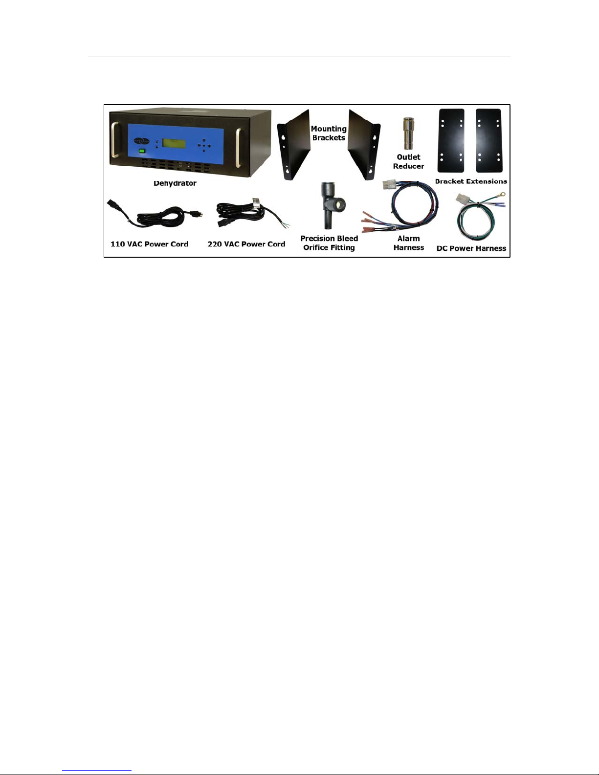
6.3 Included Contents
(1) P200W2 Series Dehydrator
(1) Installation Guide (not shown)
(1) User’s Guide (not shown)
(2) Mounting Brackets
(1) Package containing (for P200WA2 model):
Power Cord - (1) 110 VAC and (1) 220 VAC
(1) Package containing:
(2) Bracket Extensions (for 54.42 cm rack)
(1) Outlet Reducer (for 1/4” air supply line)
(1) DC Power Harness (for P200W2 and P208W2 models)
(1) Alarm Harness
(1) Precision Bleed Orifice Fitting
(1) Package of mounting hardware (not shown)
(1) Mini CD – Guides & SNMP Files
6.4 Required Tools and Materials
Medium Phillips screwdriver
7/16” wrench
Terminal crimpers
Box cutting knife
Page 12 of 82 P012213 – Rev. F
PUREGAS, LLC P200W2 Series Dehydrator User’s Guide
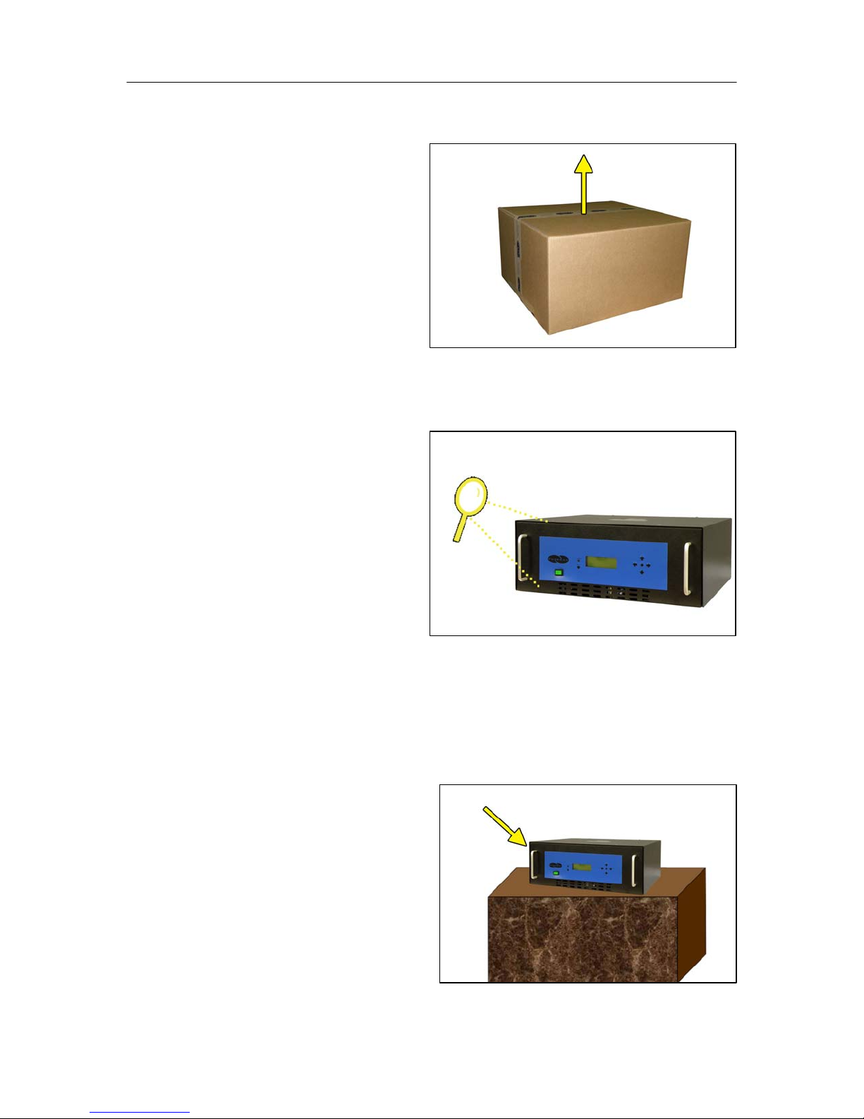
6.5 Installation Steps
6.5.1 Use a Box Cutting Knife to
open and remove the
Dehydrator and all contents
from packaging.
NOTE: If ANY SHIPPING
DAMAGE is detected, file a
claim with the shipping
company prior to continuing the installation procedures.
6.5.2 Inspect the Dehydrator for
any damage and verify
included contents
(Section 6.3 ).
NOTE: If ANY SHIPPING
DAMAGE is detected, file a
claim with the shipping
company prior to continuing the installation procedures.
6.5.3 Place the Dehydrator at the operating location:
For Bench Top Installation:
a. Place the Dehydrator on a
level surface.
Page 13 of 82 P012213 – Rev. F
PUREGAS, LLC P200W2 Series Dehydrator User’s Guide
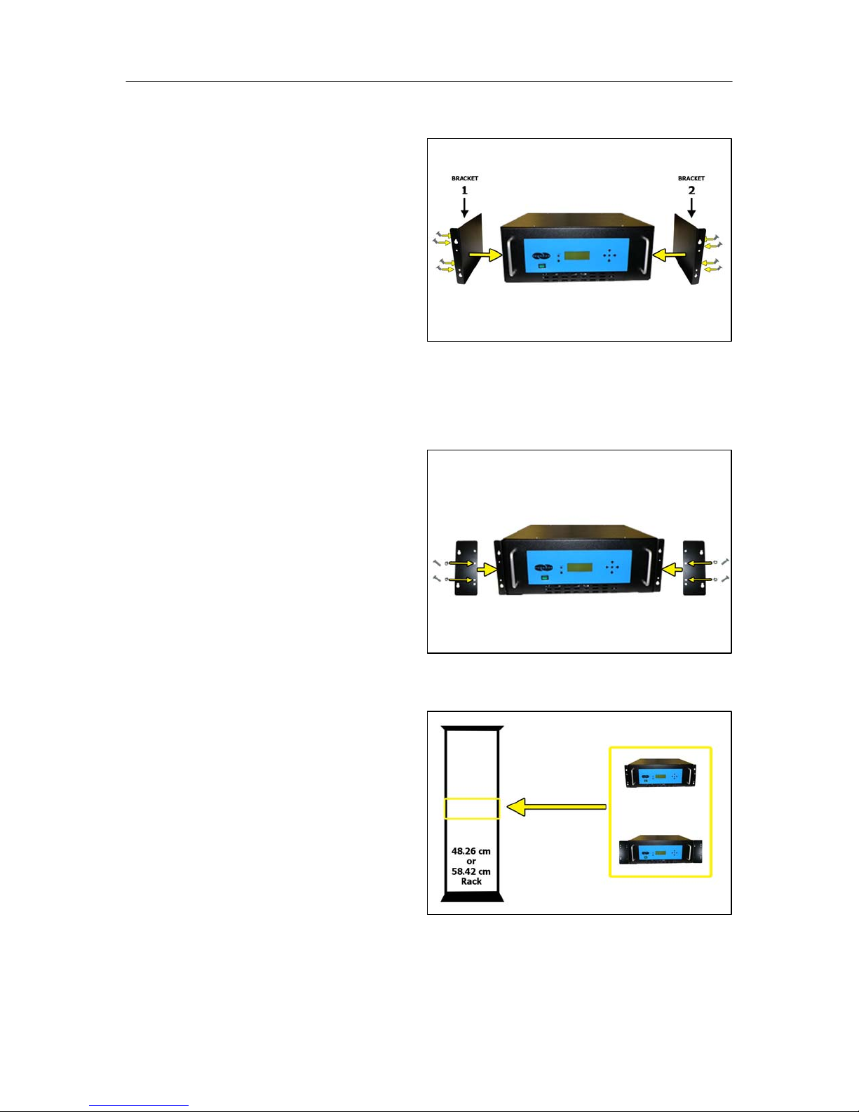
For Rack Mounted Installation:
a. Attach Mounting Brackets
to the Dehydrator with
mounting flanges facing
forward as shown.
Use Hardware A and
Phillips Head Screwdriver.
NOTE: Mounting Brackets
can be attached in a number of positions; front-to-back. Choose the
mounting position that meets your rack mounting requirement.
b. For installation on a
58.42 cm rack, attach the
Bracket Extensions to the
Mounting Brackets as
shown.
Use Hardware B, Phillips
Head Screwdriver, and
7/16” Wrench.
c. Install the Dehydrator on a
48.26 cm or 58.42 cm
Rack.
Use Hardware C and
Phillips Head Screwdriver.
Page 14 of 82 P012213 – Rev. F
PUREGAS, LLC P200W2 Series Dehydrator User’s Guide
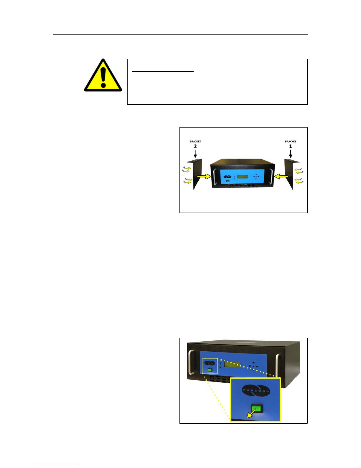
For Vertical / Wall Mounted Installation:
IMPORTANT!
a. Attach Mounting Brackets
to the Dehydrator with
mounting flanges facing
UP as shown.
Use Hardware A and
Phillips Head Screwdriver.
NOTE: Make sure the Mounting Brackets are attached in the forwardmost mounting position.
PUREGAS recommends keeping the area beneath a vertical
mounted dehydrator clear.
b. Install the Dehydrator on a wall with the Display Panel facing UP.
(Wall mounting hardware not supplied)
NOTE: To pre-drill a set of holes, horizontal spacing between bracket
holes is 46.67 cm on center.
6.5.4 Verify the Dehydrator is
powered OFF.
NOTE: POWER Button will
be in the Out position and
WILL NOT be illuminated
when power is OFF.
Page 15 of 82 P012213 – Rev. F
PUREGAS, LLC P200W2 Series Dehydrator User’s Guide
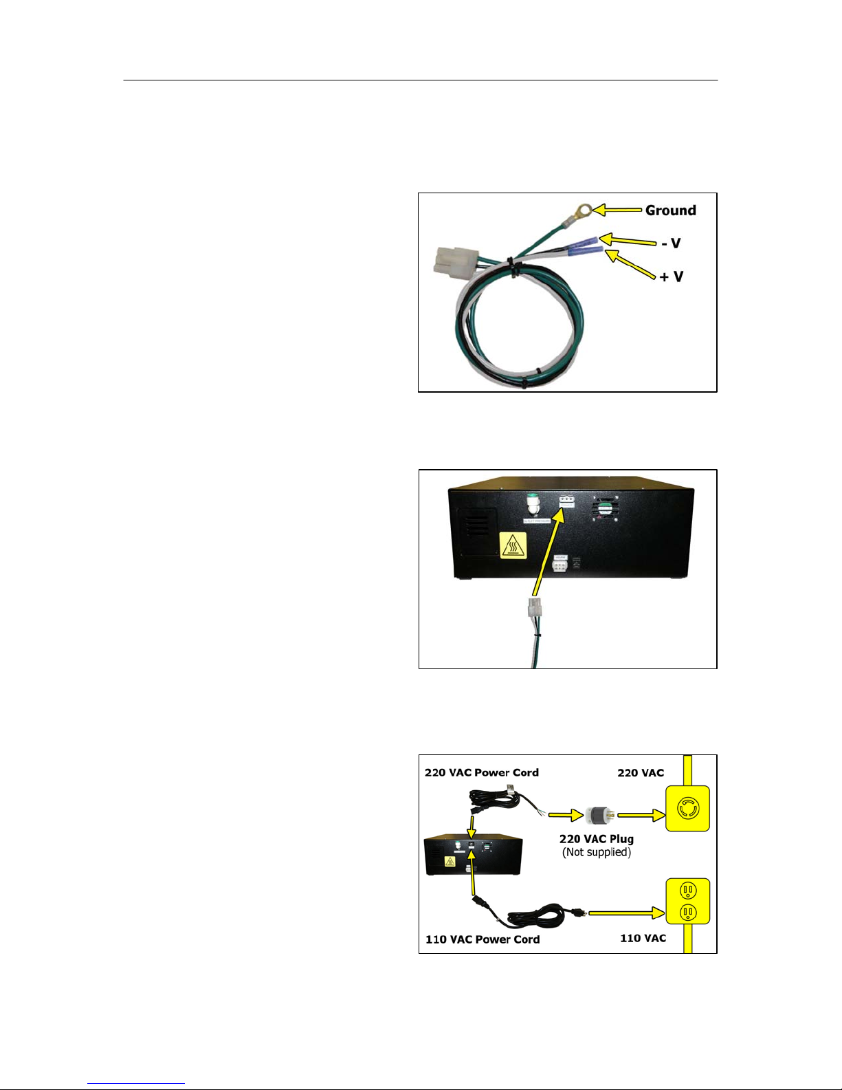
6.5.5 Connect Power to the Dehydrator:
For 24 VDC and 48 VDC Dehydrators:
a. Using Terminal Crimpers,
wire the DC Power
Harness to power supply:
WHITE: Positive Voltage
BLACK: Negative
Voltage
GREEN: Ground (Frame
or Power Supply Ground)
b. Connect the DC Power
Harness to the Power Port
on the back of the
Dehydrator.
For AC Dehydrators:
a. Plug in or wire the AC
Power Cord to power
supply:
BLACK: Line
WHITE: Neutral
GREEN: Ground
Page 16 of 82 P012213 – Rev. F

PUREGAS, LLC P200W2 Series Dehydrator User’s Guide
b. Connect the AC Power
Cord (110 VAC or 220
VAC) to the Power Port on
the back of the Dehydrator.
6.5.6 Power the Dehydrator ON.
NOTE: POWER Button and
Display Screen WILL be
illuminated when power is
ON. Otherwise, verify
wiring (Section 6.5.5 ).
NOTE: Compressor should
run briefly.
6.5.7 Remove the Outlet Port
Plug.
NOTE: Compressor should
run continuously once this
plug is removed.
6.5.8 Locate and familiarize
yourself with the Dehydrator
Control Buttons.
Page 17 of 82 P012213 – Rev. F
PUREGAS, LLC P200W2 Series Dehydrator User’s Guide
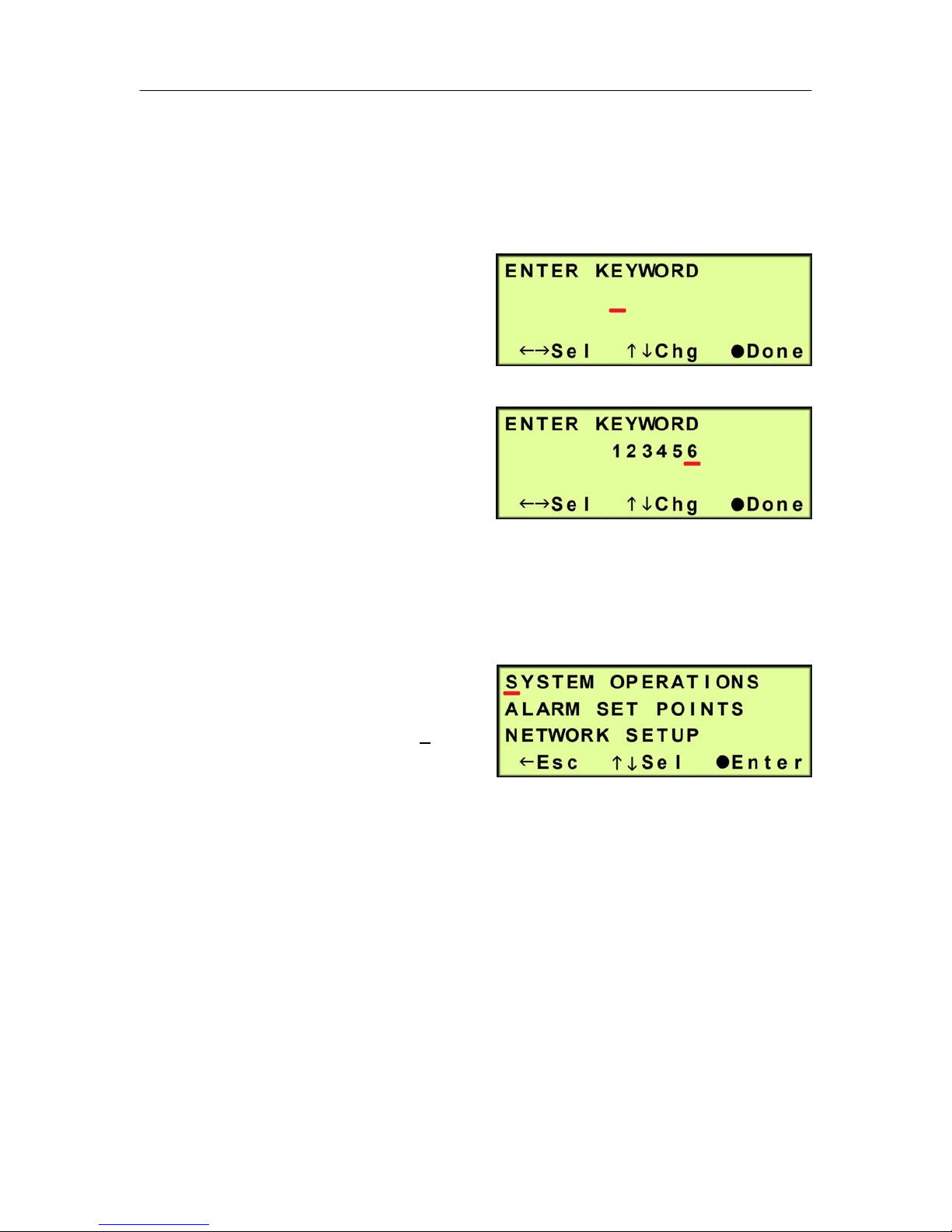
6.5.9 Press the Up () Arrow Button to access the Set Up Menu.
6.5.10 Enter the Keyword (default Keyword is 123456) –
6.5.10.1 Press the Left () &
Right () Arrow Buttons
to move the underscore
beneath the digit to change.
6.5.10.2 Press the Up () &
Down () Arrow Buttons
to change the value of the
selected digit.
6.5.10.3 Press the Function () Button when Done.
6.5.11 Press the Up () & Down ()
Arrow Buttons to move the
underscore beneath the “S” in
System Operations.
6.5.12 Press the Function () Button to Enter System Operations.
Page 18 of 82 P012213 – Rev. F
PUREGAS, LLC P200W2 Series Dehydrator User’s Guide
The System Operations Section is used to set the range for the system pressure.
When the system pressure reaches the High Pressure setting, the compressor will
turn OFF. When the system pressure reaches the Low Pressure setting, the
compressor will turn ON.
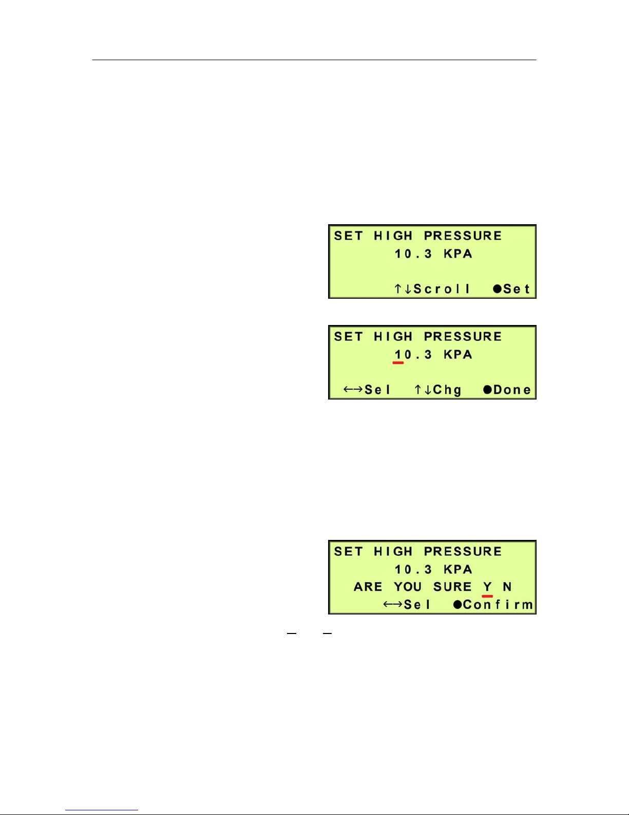
6.5.13 Set High Pressure (default setting is 10.3 KPa) –
6.5.13.1 Press the Function ()
Button to Set.
6.5.13.2 Press the Left () &
Right () Arrow Buttons
to move the underscore
beneath the digit to change.
6.5.13.3 Press the Up () & Down () Arrow Buttons to change the value of
the selected digit.
6.5.13.4 Press the Function () Button when Done.
6.5.13.5 Press the Left () &
Right () Arrow Buttons
to move the underscore
beneath the correct
confirmation choice (Yes or No).
6.5.13.6 Press the Function () Button to Confirm. This will lock in the new
setting value.
Page 19 of 82 P012213 – Rev. F
PUREGAS, LLC P200W2 Series Dehydrator User’s Guide
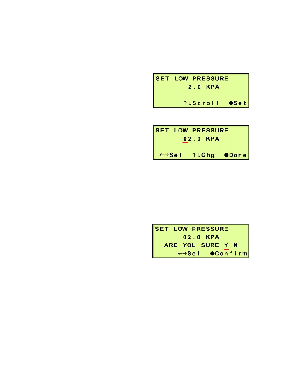
6.5.14 Press the Up () Arrow Button to access the Set Low Pressure screen.
6.5.15 Set Low Pressure (default setting is 2 KPa) –
6.5.15.1 Press the Function ()
Button to Set.
6.5.15.2 Press the Left () &
Right () Arrow Buttons to
move the underscore
beneath the digit to change.
6.5.15.3 Press the Up () & Down () Arrow Buttons to change the value of
the selected digit
6.5.15.4 Press the Function () Button when Done.
6.5.15.5 Press the Left () &
Right () Arrow Buttons
to move the underscore
beneath the correct
confirmation choice (Y
es or No).
6.5.15.6 Press the Function () Button to Confirm. This will lock in the new
setting value.
6.5.16 Press the Up () Arrow Button to access the Set Up Menu screen.
Page 20 of 82 P012213 – Rev. F
PUREGAS, LLC P200W2 Series Dehydrator User’s Guide
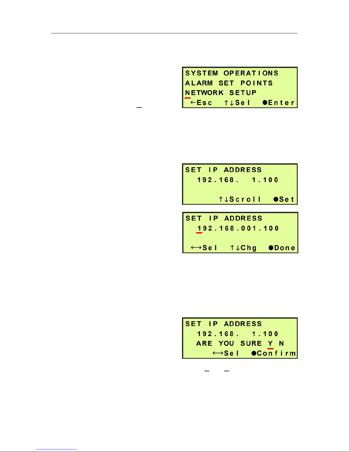
6.5.17 Set Network Configuration (if applicable) -
6.5.17.1 Press the Up () &
Down () Arrow Buttons
to move the underscore
beneath the “N” in
Network Setup.
6.5.17.2 Press the Function () Button to Enter Network Setup.
6.5.17.3 Set IP Address (default is 192.168.1.100) -
6.5.17.3.1 Press the Function
() Button to set the
IP Address.
6.5.17.3.2 Press the Left ()
& Right () Arrow
Buttons to move the
underscore beneath
the digit to change.
6.5.17.3.3 Press the Up () & Down () Arrow Buttons to change the
value of the selected digit.
6.5.17.3.4 Press the Function () Button when Done.
6.5.17.3.5 Press the Left ()
& Right () Arrow
Buttons to move the
underscore beneath
the correct confirmation choice (Yes or No).
6.5.17.3.6 Press the Function () Button to Confirm. This will lock in
the new setting value.
Page 21 of 82 P012213 – Rev. F
PUREGAS, LLC P200W2 Series Dehydrator User’s Guide
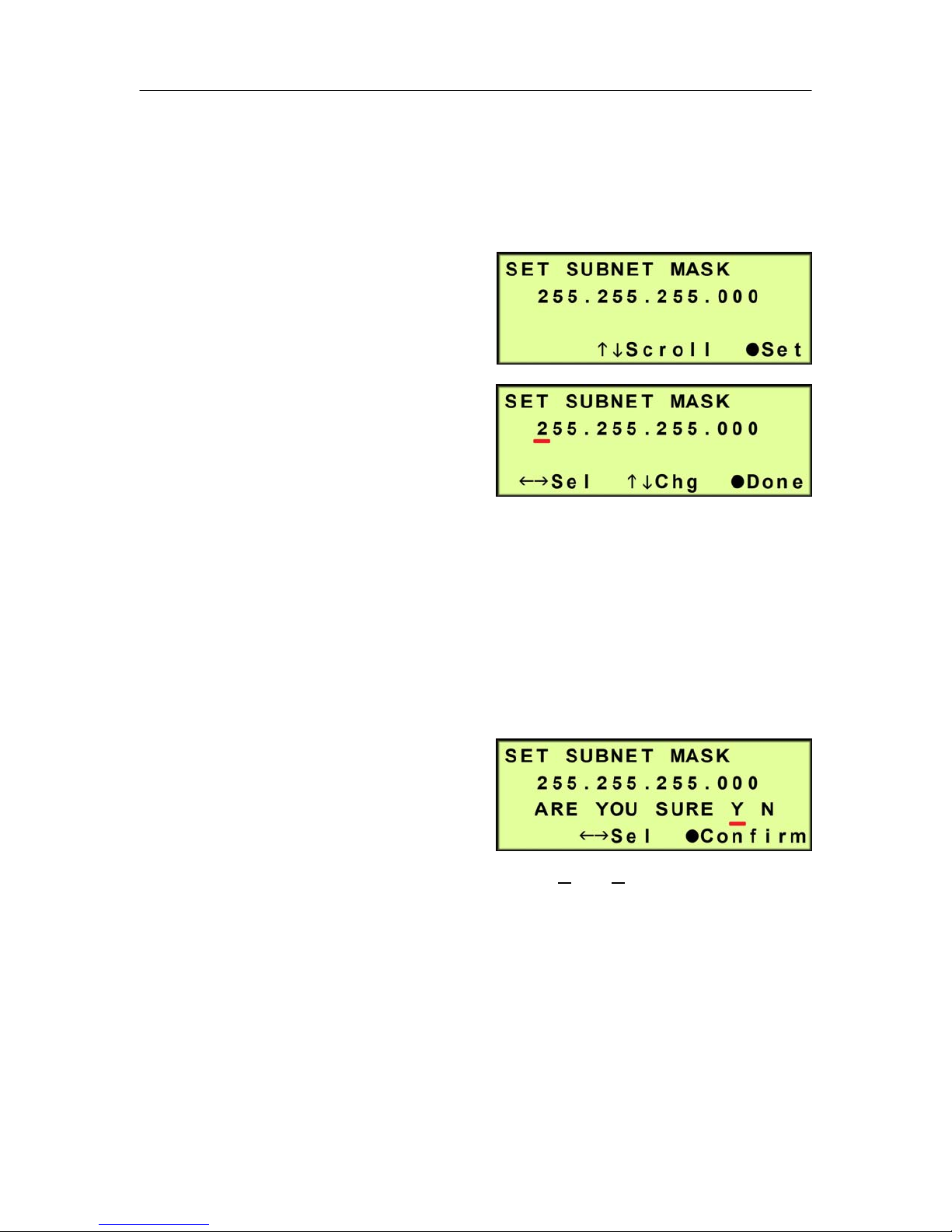
6.5.17.4 Press the Up () Arrow Button to scroll to the Set Subnet Mask
screen.
6.5.17.5 Set Subnet Mask (default is 255.255.255.000) -
6.5.17.5.1 Press the Function
() Button to Set the
Subnet Mask.
6.5.17.5.2 Press the Left ()
& Right () Arrow
Buttons to move the
underscore beneath
the digit to change.
6.5.17.5.3 Press the Up () & Down () Arrow Buttons to change the
value of the selected digit.
6.5.17.5.4 Press the Function () Button when Done.
6.5.17.5.5 Press the Left ()
& Right () Arrow
Buttons to move the
underscore beneath
the correct confirmation choice (Y
es or No).
6.5.17.5.6 Press the Function () Button to Confirm. This will lock in
the new setting value.
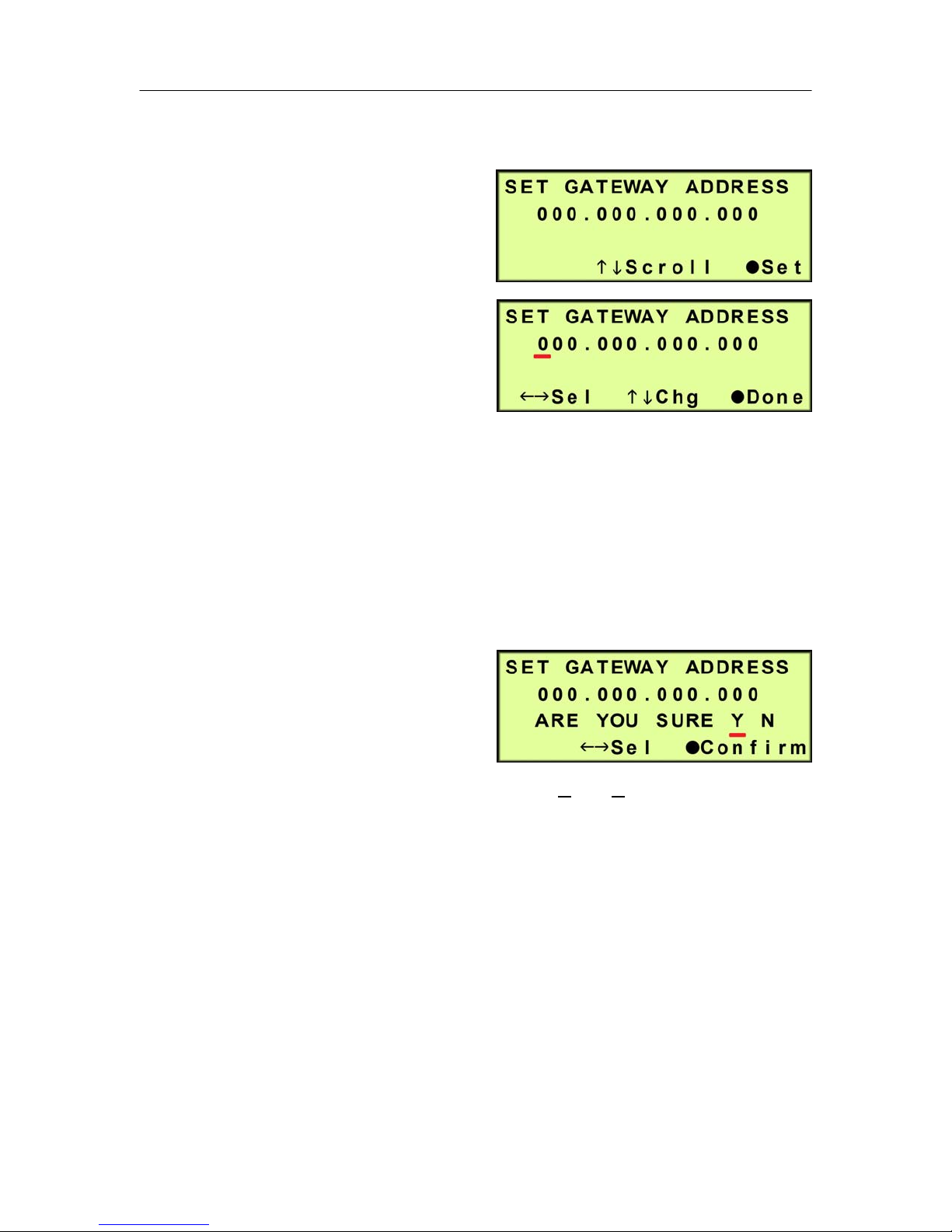
6.5.17.6 Press the Up () Arrow Button to scroll to the Set Gateway Address
screen.
Page 22 of 82 P012213 – Rev. F
PUREGAS, LLC P200W2 Series Dehydrator User’s Guide
6.5.17.7 Set Gateway Address (default is 000.000.000.000) -
6.5.17.7.1 Press the Function
() Button to Set the
Gateway Address.
6.5.17.7.2 Press the Left ()
& Right () Arrow
Buttons to move the
underscore beneath
the digit to change.
6.5.17.7.3 Press the Up () & Down () Arrow Buttons to change the
value of the selected digit.
6.5.17.7.4 Press the Function () Button when Done.
6.5.17.7.5 Press the Left ()
& Right () Arrow
Buttons to move the
underscore beneath
the correct confirmation choice (Y
es or No).
6.5.17.7.6 Press the Function () Button to Confirm. This will lock in
the new setting value.
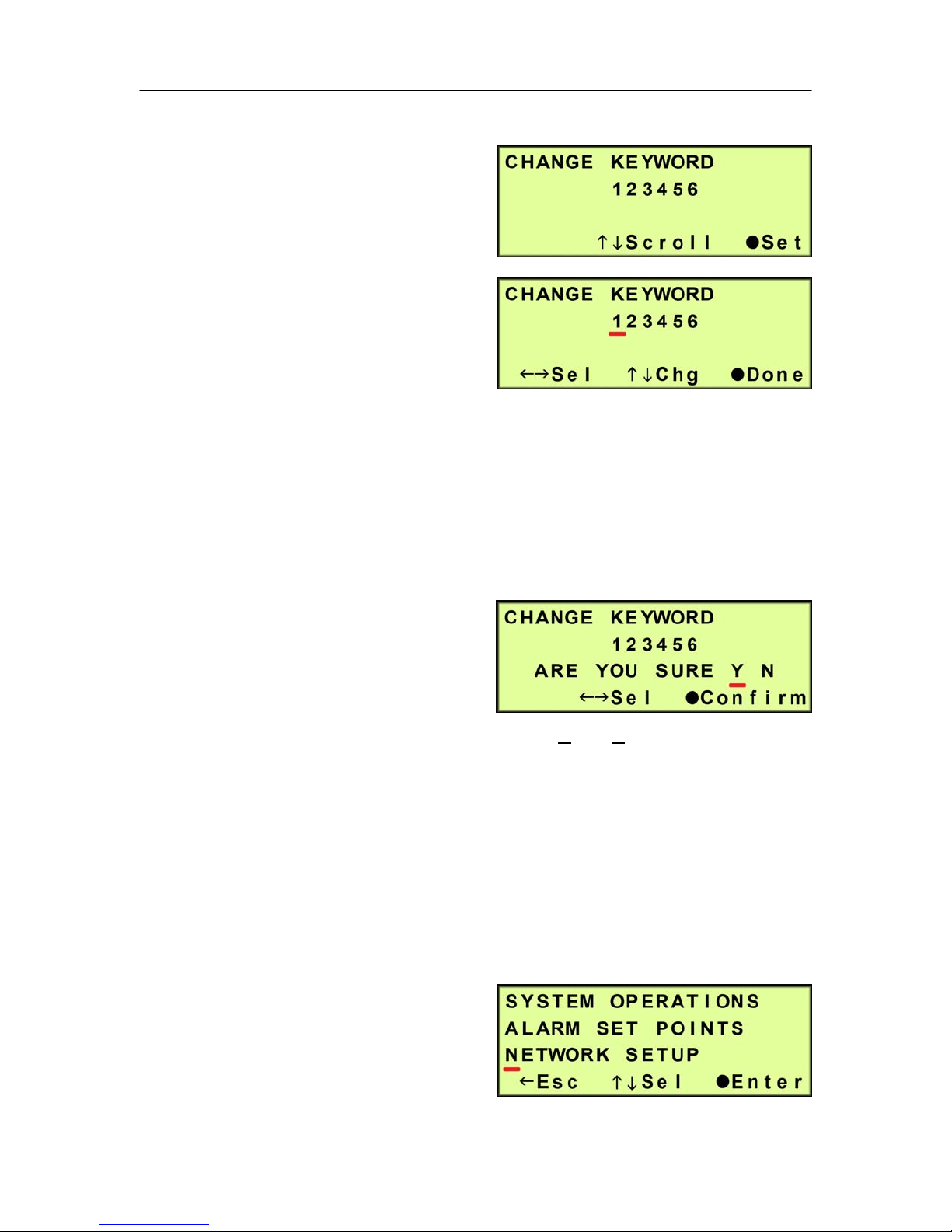
6.5.17.8 Press the Up () Arrow Button to scroll to the Change Keyword
screen.
Page 23 of 82 P012213 – Rev. F
PUREGAS, LLC P200W2 Series Dehydrator User’s Guide
6.5.17.9 Change Keyword (default is 123456)
6.5.17.9.1 Press the Function
() Button to change
the Keyword.
6.5.17.9.2 Press the Left ()
& Right () Arrow
Buttons to move the
underscore beneath
the digit to change.
6.5.17.9.3 Press the Up () & Down () Arrow Buttons to change the
value of the selected digit.
6.5.17.9.4 Press the Function () Button when Done.
6.5.17.9.5 Press the Left ()
& Right () Arrow
Buttons to move the
underscore beneath
the correct confirmation choice (Yes or No).
6.5.17.9.6 Press the Function () Button to Confirm. This will lock in
the new setting value.
6.5.17.10 Press the Up () Arrow Button to scroll to the Set Up Menu
screen.
6.5.18 Press the Left () Arrow
Button to Escape from Set Up
Menu and return to the
information screens.
Page 24 of 82 P012213 – Rev. F
PUREGAS, LLC P200W2 Series Dehydrator User’s Guide
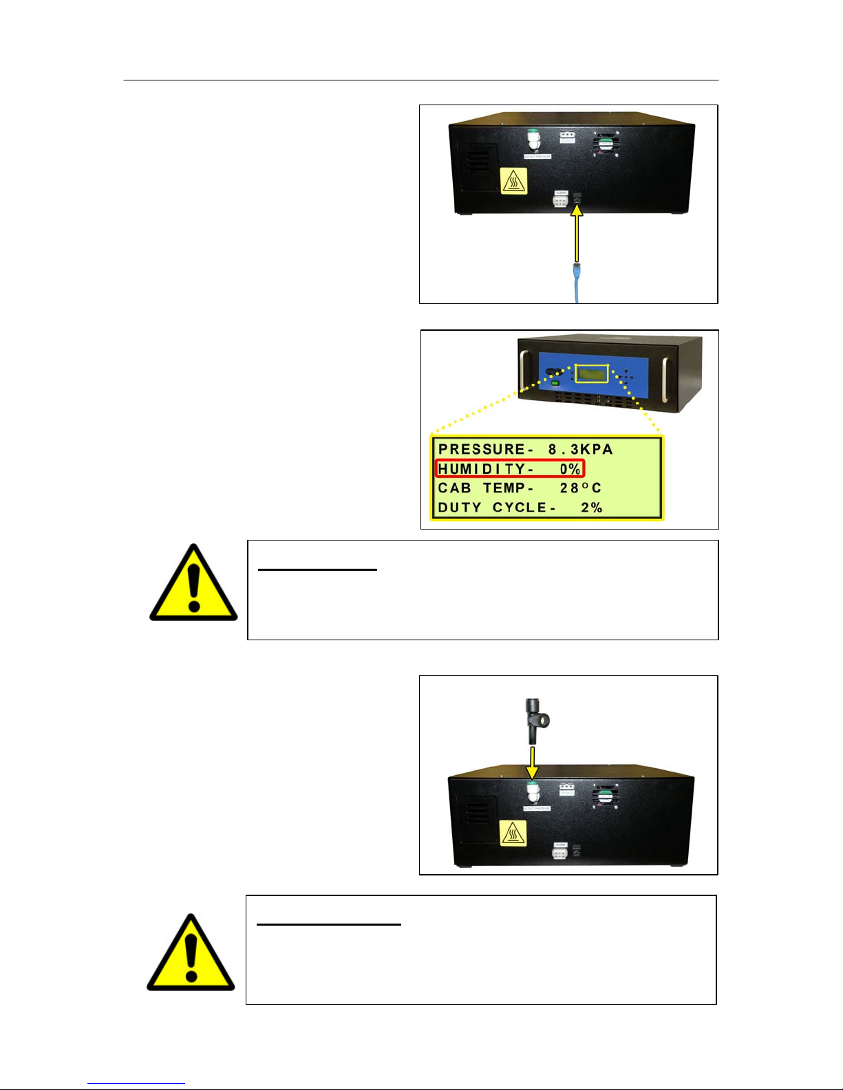
6.5.19 Connect a Network IP
cable to the UTP Port on the
back of the Dehydrator (if
applicable).
6.5.20 Let Dehydrator run until
the Humidity is 5% or below.
(May take 15 – 20 minutes).
NOTE: Press the RESET
Button if Dehydrator goes
into SHUTDOWN.
6.5.21 Connect the Precision
Bleed Orifice Fitting to the
Dehydrator Outlet Port
Fitting.
WARNING!
DO NOT CONNECT THE DEHYDRATOR TO THE SUPPLY LINE
UNTIL THE HUMIDITY READING IS 5% OR LESS.
Page 25 of 82 P012213 – Rev. F
IMPORTANT!
Installing the Precision Bleed Orifice Fitting will allow
Dehydrator to have a constant flow preventing high humidity.

PUREGAS, LLC P200W2 Series Dehydrator User’s Guide
6.5.22 Connect the air supply line
to the Dehydrator. (Use 1/4”
Reducer as required.)
NOTE: Compressor should
run until the High Pressure
setting (Section 6.5.13 ) is
reached.
6.5.23 Press the RESET Button
to clear any alarms triggered
during installation.
6.5.24 Connect the Dehydrator to Alarm Monitoring (if applicable) –
6.5.24.1 Wire the Alarm Harness to monitoring device using the table below
for reference.
Wire # Wire Color Function
Power Fail
Alarm
Common
Alarm
Common
Alarm
1 RED SHORT
4 BLACK
on Alarm
2 BLACK SHORT
5 BLUE
on Alarm
3 BLUE OPEN
6 BLACK
on Alarm
Page 26 of 82 P012213 – Rev. F

PUREGAS, LLC P200W2 Series Dehydrator User’s Guide
6.5.24.2 Connect the Alarm
Harness to the Alarm
Port on the back of the
Dehydrator.
6.5.25 REGISTER YOUR DEHYDRATOR. See Section 7. for details.
6.6 Installation Checklist
No shipping damage was detected.
Dehydrator location meets the following requirements:
o Well ventilated
o Free from abrasive dust or chemicals
o Ambient temperature is between 5° and 30° C (optimal)
High & Low Pressure was set.
Network IP, Subnet, and Gateway Addresses were set (if applicable).
Keyword changed (if applicable).
Network IP Cable connected to Dehydrator (if applicable).
Dehydrator connected to alarm monitoring (if applicable).
No alarms are present on the Display Panel.
Page 27 of 82 P012213 – Rev. F

PUREGAS, LLC P200W2 Series Dehydrator User’s Guide
7. Registering Your Dehydrator
Please take a moment to register your PUREGAS P200W2 Series Dehydrator.
Registering is necessary to activate the Limited Warranty on your product. Once you
register, you are eligible to receive free technical support, as well as updates
concerning your PUREGAS products.
Register Online at www.puregas.com/registration
Or by Phone 1-800-521-5351 (option 2)
Have the following information available:
Model #: Serial #:
Company Name: Location Name:
Shipping Address:
City: State: Zip Code :
Contact Name: Phone #: ( ) - ext.
Email:
Page 28 of 82 P012213 – Rev. F

PUREGAS, LLC P200W2 Series Dehydrator User’s Guide
8. Operating Your Dehydrator
8.1 Safety & Warning Information
WARNING!
For your safety, all the information in this User’s Guide must
be followed to minimize the risk of electrical shock, and prevent
property damage or personal injury.
WARNING!
Extreme care should be exercised to avoid contact with live
electrical circuits. Many procedures performed during
installation, operation, and testing of this Dehydrator require the
equipment to be running, creating a situation for potential electrical
shock. It is highly recommended that you remove all jewelry
before performing any procedures.
IMPORTANT!
Removing the cover or performing procedures not described in this
User’s Guide WILL VOID THE WARRANTY.
Page 29 of 82 P012213 – Rev. F

PUREGAS, LLC P200W2 Series Dehydrator User’s Guide
8.2 Connecting an Air Supply Line
WARNING!
8.2.1 Connect the Precision
Bleed Orifice Fitting to the
Dehydrator Outlet Port
Fitting.
DO NOT CONNECT THE DEHYDRATOR TO THE SUPPLY LINE
UNTIL THE HUMIDITY READING IS 5% OR LESS.
IMPORTANT!
Installing the Precision Bleed Orifice Fitting will allow
Dehydrator to have a constant flow preventing high humidity.
8.2.2 Connect the air supply line
to the Dehydrator. (Use 1/4”
Reducer as required.)
Page 30 of 82 P012213 – Rev. F

PUREGAS, LLC P200W2 Series Dehydrator User’s Guide
8.3 Powering the Dehydrator ON & OFF
CAUTION!
8.3.1 Press the POWER Button.
NOTE: POWER Button and
Display Screen WILL be
illuminated when power is
ON.
Incoming power to Dehydrator must be:
10 amp service recommended
24 VDC for P200W2 model (7 Amp slow blow fuse)
48 VDC for P208W2 model (7 amp slow blow fuse)
85 - 264 VAC, 1 Phase for P200WA2 model
(5 amp slow blow fuse)
Page 31 of 82 P012213 – Rev. F

PUREGAS, LLC P200W2 Series Dehydrator User’s Guide
8.4 Using the Front Panel Display
8.4.1 ALARM LED – Indicates an alarm is present.
CAUTION!
The Display Screen is covered by a clear protective layer that
guards against Electrostatic Discharge (ESD). DO NOT REMOVE
THIS LAYER.
8.4.2 RESET Button – Clears an alarm and allows the system to continue
operating.
8.4.3 HOLD / FUNCTION Button – Freezes the current information screen on
the display. When pressed again, it will allow the information screens to
begin cycling again. Also used as a Function Button in the Set Up Menu
screens.
8.4.4 Arrow Buttons – Used to access, navigate, and change values in the Set
Up Menu screens.
Page 32 of 82 P012213 – Rev. F

PUREGAS, LLC P200W2 Series Dehydrator User’s Guide
8.4.5 Display Screen - Shows the current Dehydrator readings and status. Will
cycle between the following information screens (unless the HOLD Button
has been pressed):
8.4.5.1 SYS STATUS Screen
SYS STATUS - Running Status of the system:
ON – System is online and drying air.
SHUTDOWN – System is shutdown as a result of a critical alarm
condition.
OPN CRCT – There is a disconnected or faulty wire. The system
will continue to operate.
TWR 1 – The current operating status of Tower 1:
TWR 2 – The current operating status of Tower 2:
IN USE – Tower is dry and being used to supply air.
READY – Tower is dry but not currently supplying air.
REGEN – Tower is in regeneration mode.
INITIAL – Tower is not determined to be dry or wet, but is being
used to supply air.
WAITING – Tower is not determined to be dry or wet, and is not
currently supplying air.
SVC RQD – Tower requires service as a result of a tower fail
alarm condition:
Page 33 of 82 P012213 – Rev. F
o Heater failure
o Overheating
o Fail to cool

PUREGAS, LLC P200W2 Series Dehydrator User’s Guide
8.4.5.2 PRESSURE Screen
PRESSURE – Current pressure of the system (will fluctuate between the
Set Low Pressure and Set High Pressure values).
HUMIDITY – Humidity level of the Dehydrator.
CAB TEMP – Temperature of the Dehydrator cabinet compartment.
DUTY CYCLE – The percentage of time the compressor is ON versus
time it is OFF in a given period of time.
8.5 Identifying Dehydrator Alarms
8.5.1 High Pressure Alarm -
Occurs when the PRESSURE
rises above the alarm set point
for more than one (1) minute.
(Default setting is 20.7 KPa)
See Section 11.5 for troubleshooting information.
8.5.2 Low Pressure Alarm -
Occurs when the PRESSURE
drops below the alarm set point
for more than one (1) minute.
(Default setting is 1.0 KPa)
Page 34 of 82 P012213 – Rev. F
See Section 11.7 for troubleshooting information.

PUREGAS, LLC P200W2 Series Dehydrator User’s Guide
8.5.3 High Humidity Alarm –
Occurs when the HUMIDITY
level rises above the alarm set
point. (Default setting is 7.0%)
If the humidity level exceeds the alarm set point for a period of time, the
Dehydrator will go into SHUTDOWN to prevent the output of wet air.
See Section 11.9 for troubleshooting information.
8.5.4 High Cabinet Temperature Alarm -
Occurs when the CAB TEMP
rises above the alarm set point
for more than one (1) minute.
(Default setting is 49 C)
If the cabinet temperature increases to 60 C or higher, the Dehydrator will
go into SHUTDOWN to protect against damage due to overheating.
See Section 11.10 for troubleshooting information.
8.5.5 Low Cabinet Temperature Alarm -
Occurs when the CAB TEMP
drops below the alarm set point
for more than one (1) minute.
(Default setting is 1 C)
If the cabinet temperature decreases to 1 C or lower, the Dehydrator will go
into SHUTDOWN to protect against damage due to freezing.
See Section 11.11 for troubleshooting information.
8.5.6 Duty Cycle Alarm -
Occurs when the Duty Cycle
rises above the alarm set point.
(Default setting is 50%)
Page 35 of 82 P012213 – Rev. F
See Section 11.12 for troubleshooting information.

PUREGAS, LLC P200W2 Series Dehydrator User’s Guide
8.6 Accessing the Set Up Menu
The Dehydrator has three (3) Set Up Sections:
System Operations – Used to set the range for the system pressure.
When the system pressure reaches the High Pressure setting, the
compressor will turn OFF. When the system pressure reaches the Low
Pressure setting, the compressor will turn ON.
Alarm Set Points – Used to set the alarm limits for specific readings.
Once the limit is reached (or exceeded) this results in an alarm.
Network Setup – Used to configure network settings including the IP
Address, Subnet Mask, Gateway Address, and Keyword.
NOTE: Reference Appendix Section 12.1 for Limits, Defaults, and Formats.
8.6.1 Press the Up () Arrow Button to access the Set Up Menu.
8.6.2 Enter Keyword (default Keyword is 123456) –
8.6.2.1 Press the Left () &
Right () Arrow Buttons
to move the underscore
beneath the digit to change.
8.6.2.2 Press the Up () & Down
() Arrow Buttons to
change the value of the
selected digit.
8.6.2.3 Press the Function () Button when Done.
8.6.2.4 Press the Up () & Down
() Arrow Buttons to move
the underscore beneath the
required menu option.
8.6.2.5 Press the Function () Button to Enter the menu selected or press the
Left () Arrow Button to Escape to the information screens.
Page 36 of 82 P012213 – Rev. F

PUREGAS, LLC P200W2 Series Dehydrator User’s Guide
8.7 Using the System Operations Menu
In the Set Up Menu:
8.7.1 Press the Up () & Down ()
Arrow Buttons to move the
underscore beneath the “S” in
System Operations.
8.7.2 Press the Function () Button to Enter System Operations.
8.7.3 Set High Pressure (default setting is 10.3 KPa) –
8.7.3.1 Press the Function ()
Button to Set.
8.7.3.2 Press the Left () &
Right () Arrow Buttons
to move the underscore
beneath the digit to change.
8.7.3.3 Press the Up () & Down () Arrow Buttons to change the value of
the selected digit.
8.7.3.4 Press the Function () Button when Done.
8.7.3.5 Press the Left () &
Right () Arrow Buttons
to move the underscore
beneath the correct
confirmation choice (Y
es or No).
8.7.3.6 Press the Function () Button to Confirm. This will lock in the new
setting value.
Page 37 of 82 P012213 – Rev. F

PUREGAS, LLC P200W2 Series Dehydrator User’s Guide
8.7.4 Press the Up () Arrow Button to access the next screen.
8.7.5 Set Low Pressure (default setting is 2 KPa) –
8.7.5.1 Press the Function ()
Button to Set.
8.7.5.2 Press the Right () &
Left () Arrow Buttons to
move the underscore
beneath the digit to change.
8.7.5.3 Press the Up () & Down () Arrow Buttons to change the value of
the selected digit.
8.7.5.4 Press the Function () Button when Done.
8.7.5.5 Press the Left () &
Right () Arrow Buttons
to move the underscore
beneath the correct
confirmation choice (Yes or No).
8.7.5.6 Press the Function () Button to Confirm. This will lock in the new
setting value.
8.7.5.7 Press the Up () Arrow Button to access the next screen.
Page 38 of 82 P012213 – Rev. F

PUREGAS, LLC P200W2 Series Dehydrator User’s Guide
8.8 Using the Alarm Set Points Menu
In the Set Up Menu:
8.8.1 Press the Up () & Down ()
Arrow Buttons to move the
underscore beneath the “A” in
Alarm Set Points.
8.8.1.1 Press the Function () Button to Enter Alarm Set Points.
8.8.2 Set High Pressure Alarm Point (default setting is 20.7 KPa) -
8.8.2.1 Press the Function ()
Button to Set.
8.8.2.2 Press the Left () &
Right () Arrow Buttons
to move the underscore
beneath the digit to change.
8.8.2.3 Press the Up () & Down () Arrow Buttons to change the value of
the selected digit.
8.8.2.4 Press the Function () Button when Done.
8.8.2.5 Press the Left () &
Right () Arrow Buttons
to move the underscore
beneath the correct
confirmation choice (Yes or No).
8.8.2.6 Press the Function () Button to Confirm. This will lock in the new
setting value.
Page 39 of 82 P012213 – Rev. F

PUREGAS, LLC P200W2 Series Dehydrator User’s Guide
8.8.3 Press the Up () Arrow Button to access the next screen.
8.8.4 Set Low Pressure Alarm Point (default setting is 1.0 KPa) –
8.8.4.1 Press the Function ()
Button to Set.
8.8.4.2 Press the Left () &
Right () Arrow Buttons
to move the underscore
beneath the digit to change.
8.8.4.3 Press the Up () & Down () Arrow Buttons to change the value of
the selected digit.
8.8.4.4 Press the Function () Button when Done.
8.8.4.5 Press the Left () &
Right () Arrow Buttons
to move the underscore
beneath the correct
confirmation choice (Y
es or No).
8.8.4.6 Press the Function () Button to Confirm. This will lock in the new
setting value.
8.8.5 Press the Up () Arrow Button to access the next screen.
Page 40 of 82 P012213 – Rev. F

PUREGAS, LLC P200W2 Series Dehydrator User’s Guide
8.8.6 Set High Cabinet Temperature Alarm Point (default setting is 49 C)
8.8.6.1 Press the Function ()
Button to Set.
8.8.6.2 Press the Left () &
Right () Arrow Buttons
to move the underscore
beneath the digit to change.
8.8.6.3 Press the Up () & Down () Arrow Buttons to change the value of
the selected digit.
8.8.6.4 Press the Function () Button when Done.
8.8.6.5 Press the Left () &
Right () Arrow Buttons
to move the underscore
beneath the correct
confirmation choice (Yes or No).
8.8.6.6 Press the Function () Button to Confirm. This will lock in the new
setting value.
8.8.7 Press the Up () Arrow Button to access the next screen.
Page 41 of 82 P012213 – Rev. F

PUREGAS, LLC P200W2 Series Dehydrator User’s Guide
8.8.8 Set Low Cabinet Temperature Alarm Point (default setting is 1 C)
8.8.8.1 Press the Function ()
Button to Set.
8.8.8.2 Press the Left () &
Right () Arrow Buttons
to move the underscore
beneath the digit to change.
8.8.8.3 Press the Up () & Down () Arrow Buttons to change the value of
the selected digit.
8.8.8.4 Press the Function () Button when Done.
8.8.8.5 Press the Left () &
Right () Arrow Buttons
to move the underscore
beneath the correct
confirmation choice (Yes or No).
8.8.8.6 Press the Function () Button to confirm. This will lock in the new
setting value.
8.8.9 Press the Up () Arrow Button to access the next screen.
Page 42 of 82 P012213 – Rev. F

PUREGAS, LLC P200W2 Series Dehydrator User’s Guide
8.8.10 Set High Humidity Alarm Point (default setting is 7%) –
8.8.10.1 Press the Function ()
Button to Set.
8.8.10.2 Press the Left () &
Right () Arrow Buttons
to move the underscore
beneath the digit to
change.
8.8.10.3 Press the Up () & Down () Arrow Buttons to change the value of
the selected digit.
8.8.10.4 Press the Function () Button when Done.
8.8.10.5 Press the Left () &
Right () Arrow Buttons
to move the underscore
beneath the correct
confirmation choice (Y
es or No).
8.8.10.6 Press the Function () Button to Confirm. This will lock in the new
setting value.
8.8.11 Press the Up () Arrow Button to access the next screen.
Page 43 of 82 P012213 – Rev. F

PUREGAS, LLC P200W2 Series Dehydrator User’s Guide
8.8.12 Set High Duty Cycle Alarm Point (default setting is 50%) -
8.8.12.1 Press the Function ()
Button to Set.
8.8.12.2 Press the Left () &
Right () Arrow Buttons
to move the underscore
beneath the digit to change.
8.8.12.3 Press the Up () & Down () Arrow Buttons to change the value of
the selected digit.
8.8.12.4 Press the Function () Button when Done.
8.8.12.5 Press the Left () &
Right () Arrow Buttons
to move the underscore
beneath the correct
confirmation choice (Yes or No).
8.8.12.6 Press the Function () Button to confirm. This will lock in the new
setting value.
8.8.13 Press the Up () Arrow Button to access the Set Up Menu screen.
Page 44 of 82 P012213 – Rev. F

PUREGAS, LLC P200W2 Series Dehydrator User’s Guide
8.9 Using the Network Setup Menu
In the Set Up Menu:
8.9.1 Press the Up () & Down ()
Arrow Buttons to move the
underscore under the “N” in
Network Setup.
8.9.1.1 Press the Function () Button to Enter Network Setup.
8.9.2 Set IP Address (default is 192.168.1.100) -
8.9.2.1 Press the Function ()
Button to Set the IP
Address.
8.9.2.2 Press the Left () &
Right () Arrow Buttons
to move the underscore
beneath the digit to change.
8.9.2.3 Press the Up () & Down () Arrow Buttons to change the value of
the selected digit.
8.9.2.4 Press the Function () Button when Done.
8.9.2.5 Press the Left () &
Right () Arrow Buttons
to move the underscore
beneath the correct
confirmation choice (Yes or No).
8.9.2.6 Press the Function () Button to Confirm. This will lock in the new
setting value.
Page 45 of 82 P012213 – Rev. F

PUREGAS, LLC P200W2 Series Dehydrator User’s Guide
8.9.3 Press the Up () Arrow Button to access the next screen.
8.9.4 Set Subnet Mask (default is 255.255.255.000) -
8.9.4.1 Press the Function ()
Button to Set the Subnet
Mask.
8.9.4.2 Press the Left () &
Right () Arrow Buttons
to move the underscore
beneath the digit to change.
8.9.4.3 Press the Up () & Down () Arrow Buttons to change the value of
the selected digit.
8.9.4.4 Press the Function () Button when Done.
8.9.4.5 Press the Left () &
Right () Arrow Buttons
to move the underscore
beneath the correct
confirmation choice (Y
es or No).
8.9.4.6 Press the Function () Button to Confirm. This will lock in the new
setting value.
8.9.5 Press the Up () Arrow Button to access the next screen.
Page 46 of 82 P012213 – Rev. F

PUREGAS, LLC P200W2 Series Dehydrator User’s Guide
8.9.6 Set Gateway Address (default is 000.000.000.000) -
8.9.6.1 Press the Function ()
Button to Set the Gateway
Address.
8.9.6.2 Press the Left () &
Right () Arrow Buttons
to move the underscore
beneath the digit to change.
8.9.6.3 Press the Up () & Down () Arrow Buttons to change the value of
the selected digit.
8.9.6.4 Press the Function () Button when Done.
8.9.6.5 Press the Left () &
Right () Arrow Buttons
to move the underscore
beneath the correct
confirmation choice (Yes or No).
8.9.6.6 Press the Function () Button to Confirm. This will lock in the new
setting value.
8.9.7 Press the Up () Arrow Button to access the next screen.
Page 47 of 82 P012213 – Rev. F

PUREGAS, LLC P200W2 Series Dehydrator User’s Guide
8.9.8 Change Keyword (default is 123456)
8.9.8.1 Press the Function ()
Button to change the
Keyword.
8.9.8.2 Press the Left () &
Right () Arrow Buttons
to move the underscore
beneath the digit to change.
8.9.8.3 Press the Up () & Down () Arrow Buttons to change the value of
the selected digit.
8.9.8.4 Press the Function () Button when Done.
8.9.8.5 Press the Left () &
Right () Arrow Buttons
to move the underscore
beneath the correct
confirmation choice (Yes or No).
8.9.8.6 Press the Function () Button to Confirm. This will lock in the new
setting value.
8.9.9 Press the Up () Arrow Button to access the Set Up Menu screen.
Page 48 of 82 P012213 – Rev. F

PUREGAS, LLC P200W2 Series Dehydrator User’s Guide
8.10 Connecting Alarms
8.10.1 Wire the Alarm Harness to monitoring device using the table below for
reference.
Wire # Wire Color Function
Power Fail
Alarm
Common
Alarm
Common
Alarm
8.10.2 Connect the Alarm
Harness to the Alarm Port on
1 RED SHORT
4 BLACK
on Alarm
2 BLACK SHORT
5 BLUE
on Alarm
3 BLUE OPEN
6 BLACK
on Alarm
the back of the Dehydrator.
8.11 Connecting an IP Cable
8.11.1 Connect an IP cable to the
UTP Port on the back of the
Dehydrator.
Page 49 of 82 P012213 – Rev. F

PUREGAS, LLC P200W2 Series Dehydrator User’s Guide
8.12 Connecting via Web Browser
If the Dehydrator IS connected to an IP network:
The Dehydrator must be configured with a valid IP Address, Subnet Mask,
and Gateway Address for the network.
An IP cable is connecting the Dehydrator to the network.
Use a computer that is on the same network as the Dehydrator.
Use Internet Explorer (6.0 or newer) or Mozilla Firefox Web Browser.
If the Dehydrator IS NOT connected to an IP network and has not been
configured with IP information (Section 8.9 ) :
Use the default IP Address (192.168.1.100) of the dehydrator to connect.
Use a Cross-over IP Cable plugged directly into a Laptop/PC and the other
end plugged into the UTP Port on the back of the Dehydrator.
Configure the network card on the Laptop/PC to use the IP Address
192.168.1.101. This will make the Laptop/PC compatible with the
Dehydrator.
Use Internet Explorer (6.0 or newer) or Mozilla Firefox Web Browser.
8.12.1 Type the IP Address of the P200W2 Series Dehydrator in the Address
text box of the web browser.
Page 50 of 82 P012213 – Rev. F

PUREGAS, LLC P200W2 Series Dehydrator User’s Guide
The Web Browser connection offers five (5) screens to the user:
Status Screen - Displays the readings and alarms monitored in the
P200W2 Series Dehydrator. Provides remote ALARM RESET.
Setup Screen - All configurations of Set Points, Setups, and Keyword
can be made in this screen.
Event Screen - Displays all events such as alarms, changes made, and
alarm resets registered by the P200W2 Series Dehydrator. This screen
is informational only.
Alarm Screen - Displays all the Alarms registered by the P200W2
Series Dehydrator. This screen is informational only.
Firmware Screen – Allows the user to upload any software updates or
upgrades to the P200W2 Series Dehydrator.
8.12.2 Click on the Menu Bar selection to access a specific screen.
Page 51 of 82 P012213 – Rev. F

PUREGAS, LLC P200W2 Series Dehydrator User’s Guide
8.13 Using the Status Screen
Displays the readings and alarms monitored in the P200W2 Series Dehydrator.
Provides remote ALARM RESET.
Readings are displayed in BLACK unless an alarm is present.
Alarms are displayed in RED next to the parameter in alarm.
Alarm Status will display Alarm if any alarms are present.
Keyword validation is required for ALARM RESET.
Page 52 of 82 P012213 – Rev. F

PUREGAS, LLC P200W2 Series Dehydrator User’s Guide
8.13.1 Resetting an Alarm
8.13.1.1 Click on the ALARM RESET Button to remotely reset Dehydrator
alarms displayed on Status Screen.
8.13.1.2 Enter Keyword (default is 123456)
8.13.1.3 Click on SUBMIT Button when done.
Page 53 of 82 P012213 – Rev. F

PUREGAS, LLC P200W2 Series Dehydrator User’s Guide
8.14 Using the Setup Screen
All configurations of Set Points, Setups, and Keyword can be made in this screen.
NOTE: Reference Appendix Section 12.1 for Limits, Defaults, and Formats.
Values in BLUE represent the current setting.
The ENTER Button is used to change values.
The CHANGE KEYWORD Button allows you to configure a new Keyword.
Keyword validation is required for the following:
o Changing a Set Point value
o Changing the Keyword
Page 54 of 82 P012213 – Rev. F

PUREGAS, LLC P200W2 Series Dehydrator User’s Guide
8.14.1 Changing a Set Point or Setup value:
8.14.1.1 Click on the value to change (in BLUE).
8.14.1.2 Type in the new value.
8.14.1.3 Click the ENTER Button when done.
8.14.1.4 Enter Keyword (default is 123456)
8.14.1.5 Click on SUBMIT Button when done. This will lock in the new
setting value.
Page 55 of 82 P012213 – Rev. F

PUREGAS, LLC P200W2 Series Dehydrator User’s Guide
8.14.2 Changing the Keyword
8.14.2.1 Click on CHANGE KEYWORD Button to change the keyword.
8.14.2.2 Type the Old Keyword.
8.14.2.3 Type the New Keyword.
8.14.2.4 Type the Confirm New Keyword.
8.14.2.5 Click on SUBMIT Button to confirm. This will lock in the new
setting value.
Page 56 of 82 P012213 – Rev. F

PUREGAS, LLC P200W2 Series Dehydrator User’s Guide
8.15 Using the Event Screen
Displays all events such as alarms, changes made, and alarm resets registered by
the P200W2 Series Dehydrator. This screen is informational only.
Click on the column headings to sort data according to that column.
Click the Arrow Buttons to navigate through all the event log pages.
Page 57 of 82 P012213 – Rev. F

PUREGAS, LLC P200W2 Series Dehydrator User’s Guide
8.16 Using the Alarm Screen
Displays all the Alarms registered by the P200W2 Series Dehydrator. This screen
is informational only.
Click on the column headings to sort data according to that column.
Click the Arrow Buttons to navigate through all the event log pages.
Page 58 of 82 P012213 – Rev. F

PUREGAS, LLC P200W2 Series Dehydrator User’s Guide
8.17 Using the Firmware Screen
Displays the current firmware version and date of the P200W2 Series
Dehydrators.
Current Version: Displays the current firmware version of the P200W2 Series
Dehydrator.
New Version File: Displays the new location and new firmware version
chosen.
The BROWSE Button allows you to locate the new firmware file.
The ACCEPT Button is used to change values.
Keyword validation is required to update firmware.
Page 59 of 82 P012213 – Rev. F

PUREGAS, LLC P200W2 Series Dehydrator User’s Guide
8.17.1 Updating the Firmware:
8.17.1.1 Click on BROWSE Button to locate the firmware file.
8.17.1.2 Navigate and Select the correct .bin file. Press the OK Button.
8.17.1.3 Click the ACCEPT Button when done
8.17.1.4 Enter Keyword (default is 123456)
8.17.1.5 Click on SUBMIT Button when done. This will lock in the new
firmware version.
Page 60 of 82 P012213 – Rev. F

PUREGAS, LLC P200W2 Series Dehydrator User’s Guide
8.18 Connecting via SNMP
Using SNMP to connect and communicate with the P200W2 Series Dehydrator is
dependent upon the specific SNMP Management software used on your network.
This software requires a SNMP Definition & Configuration File (MIB file) in
order to properly communicate with the Dehydrator. This file is named
“PuregasP200W2.mib” and is located on the Mini CD included with your
Dehydrator. It is necessary to import this file into your SNMP Management
software.
NOTE: Reference Appendix Section 12.2 for a list of SNMP Parameters
including Limits, Defaults, and Formats.
Page 61 of 82 P012213 – Rev. F

PUREGAS, LLC P200W2 Series Dehydrator User’s Guide
9. Testing Your Dehydrator
9.1 Safety & Warning Information
WARNING!
For your safety, all the information in this User’s Guide must
be followed to minimize the risk of electrical shock, and prevent
property damage or personal injury.
WARNING!
Extreme care should be exercised to avoid contact with live
electrical circuits. Many procedures performed during
installation, operation, and testing of this Dehydrator require the
equipment to be running, creating a situation for potential electrical
shock. It is highly recommended that you remove all jewelry
before performing any procedures.
CAUTION!
Incoming power to Dehydrator must be:
10 amp service recommended
24 VDC for P200W2 model (7 Amp slow blow fuse)
48 VDC for P208W2 model (7 amp slow blow fuse)
85 - 264 VAC, 1 Phase for P200WA2 model
(5 amp slow blow fuse)
Page 62 of 82 P012213 – Rev. F
IMPORTANT!
Removing the cover or performing procedures not described in this
User’s Guide WILL VOID THE WARRANTY.

PUREGAS, LLC P200W2 Series Dehydrator User’s Guide
9.2 Measuring Incoming Voltage
WARNING!
9.2.1 Power the Dehydrator OFF (Section 8.3 ).
9.2.2 For P200W2 and P208W2 models:
9.2.2.1 Disconnect the DC
Extreme care should be exercised to avoid contact with live
electrical circuits. It is highly recommended that you remove all
jewelry before performing any procedures.
Power Harness from the
Power Port on the back
of the Dehydrator.
9.2.2.2 Place Voltmeter
probes inside the DC
Power Harness
connector socket:
RED probe to
WHITE wire
BLACK probe to
BLACK wire
The voltage should measure 24 VDC for the P200W2 model and 48
VDC for the P208W2 model.
9.2.2.3 Re-connect the DC Power Harness to the Power Port on the back of
the Dehydrator.
Page 63 of 82 P012213 – Rev. F

PUREGAS, LLC P200W2 Series Dehydrator User’s Guide
9.2.3 For P200WA2 model:
WARNING!
9.2.3.1 Disconnect the AC
9.2.3.2 Using a Voltmeter,
Extreme care should be exercised to avoid contact with live
electrical circuits. If unsure about performing the following
procedure, contact an electrician.
Power Cord from the
Power Port on the back
of the Dehydrator.
place the probes inside
the AC Power Cord
LINE & NEUTRAL
plug openings.
(Not GROUND)
The voltage should measure 85 - 264 VAC.
9.2.3.3 Re-connect the AC Power Cord to the Power Port on the back of the
Dehydrator.
9.2.4 Power the Dehydrator ON (Section 8.3 ).
Page 64 of 82 P012213 – Rev. F

PUREGAS, LLC P200W2 Series Dehydrator User’s Guide
9.3 Testing High Pressure Alarm
NOTE: All testing values are based on default Dehydrator settings, if settings
have been changed, adjust testing values accordingly.
9.3.1 Make note of the current
High Pressure setting.
(Section 8.4.5.2 )
9.3.2 Set High Pressure (Section
8.7.3 ) over 20.7 KPa.
After one (1) minute, the
High Pressure Alarm should
appear on the display.
9.3.3 Set High Pressure back to
setting recorded in step 9.3.1
9.3.4 Press the RESET Button to
clear the alarm.
If you are unable to create a High Pressure Alarm as described, see Section 11.6
for troubleshooting information.
Page 65 of 82 P012213 – Rev. F

PUREGAS, LLC P200W2 Series Dehydrator User’s Guide
9.4 Testing Low Pressure Alarm
NOTE: All testing values are based on default Dehydrator settings, if settings
have been changed, adjust testing values accordingly.
9.4.1 Make note of the current
Low Pressure setting.
(Section 8.4.5.1 )
9.4.2 Set Low Pressure (Section
8.7.5 ) below 1.0 KPa.
After one (1) minute, the
Low Pressure Alarm should
appear on the display.
9.4.3 Set Low Pressure back to
setting recorded in step 9.4.1
9.4.4 Press the RESET Button to clear the alarm.
If you are unable to create a Low Pressure Alarm as described, see Section 11.8
for troubleshooting information.
Page 66 of 82 P012213 – Rev. F

PUREGAS, LLC P200W2 Series Dehydrator User’s Guide
9.5 Testing High Duty Cycle Alarm
NOTE: All testing values are based on default Dehydrator settings, if settings
have been changed, adjust testing values accordingly.
9.5.1 Press the HOLD Button on
PRESSURE Screen.
9.5.2 Disconnect air supply line
from Dehydrator Outlet Port
Fitting.
9.5.3 Verify ths Duty Cycle
alarm appears on the display
after 20 - 60 seconds.
Page 67 of 82 P012213 – Rev. F

PUREGAS, LLC P200W2 Series Dehydrator User’s Guide
9.5.4 Reconnect air supply line to
Dehydrtator.
9.5.5 Press the RESET Button to clear the alarm.
If you are unable to create a Duty Cycle Alarm as described, see Section 11.13
for troubleshooting information.
Page 68 of 82 P012213 – Rev. F

PUREGAS, LLC P200W2 Series Dehydrator User’s Guide
10. Service & Repair
Only PUREGAS can offer factory direct rebuilds backed by a 6 month factory warranty.
2 week turnaround time
Estimates available upon request
Minimum service charge fee applies
10.1 Services Offered
Piston Compressor Rebuild
o Replace motor bearings, piston rod assemblies, and install a
complete compressor maintenance kit.
o Test air flow, air pressure, and electrical performance
Heatless Dryer Rebuild
o Replace desiccant, o-rings, check valves, springs, and complete
solenoid assembly
o Test proper component operation
Desiccant Tower Repack
o Clean out tower and replace desiccant, filter, and o-ring
Circuit Board Repair (Limited to current model boards only)
Complete Dehydrator Repair
10.2 Initiating a Service Transaction
Contact our Parts & Service Department at 1-800-521-5351 (option 3)
to obtain a Return Authorization (RA) number.
Carefully package the item(s) to be returned.
Mark the Return Authorization (RA) number on the outside of the
shipping container.
Include the main address and phone number of the individual to contact
for related inquiry and follow-up information.
Include the purchase order number.
Page 69 of 82 P012213 – Rev. F

PUREGAS, LLC P200W2 Series Dehydrator User’s Guide
11. Troubleshooting Your Dehydrator
11.1 Before You Call PUREGAS
PLEASE READ THIS SECTION FIRST. It is important that you use the
following sections in order to diagnose and attempt to fix the problem with your
Dehydrator before placing a call to PUREGAS Technical Support.
This troubleshooting guide is intended to simplify the isolation of problems, present
possible causes, provide test procedures for verification, and suggest corrective
actions to restore the Dehydrator back to normal operation. Each section begins with
the most likely cause(s) of the issue. Otherwise, they start from the simplest
possibilities and progress to more complicated ones.
This troubleshooting guide is designed to be easy to follow and very effective when
used properly. It is suggested to always start at the beginning of the specific problem
section and continue in sequence, following the procedures indicated.
11.2 Safety & Warning Information
WARNING!
For your safety, all the information in this User’s Guide must
be followed to minimize the risk of electrical shock, and prevent
property damage or personal injury.
IMPORTANT!
Removing the cover or performing procedures not described in this
User’s Guide WILL VOID THE WARRANTY.
Page 70 of 82 P012213 – Rev. F

PUREGAS, LLC P200W2 Series Dehydrator User’s Guide
WARNING!
Extreme care should be exercised to avoid contact with live
electrical circuits. Many procedures performed during
installation, operation, and testing of this Dehydrator require the
equipment to be running, creating a situation for potential electrical
shock. It is highly recommended that you remove all jewelry
before performing any procedures.
CAUTION!
Incoming power to Dehydrator must be:
10 amp service recommended
24 VDC for P200W2 model (7 Amp slow blow fuse)
48 VDC for P208W2 model (7 amp slow blow fuse)
85 - 264 VAC, 1 Phase for P200WA2 model
(5 amp slow blow fuse)
CAUTION!
Using the pressure relief valve equipped with this unit as the only
means of over pressurization protection for the connected system is
not advised.
Page 71 of 82 P012213 – Rev. F

PUREGAS, LLC P200W2 Series Dehydrator User’s Guide
11.3 Dehydrator Won’t Power ON
Possible Cause Check Corrective Action
POWER Button in
OFF position
No incoming voltage to
Dehydrator
For DC models:
Incoming voltage is
wired for Negative
voltage
Defective Dehydrator
(if incoming voltage is
present and correct)
Verify POWER Button
is in ON position
(Section 8.3 )
Measure incoming
voltage (Section 9.2 )
Verify incoming voltage
is wired as Positive
voltage (Section 9.2 )
Verify incoming voltage
(Section 9.2 )
Move POWER Button
to ON position
(Section 8.3 )
Troubleshoot facility
power supply to
Dehydrator
Swap the WHITE and
BLACK power leads on
the DC Power Harness
Contact PUREGAS
Technical Support
(Section 11.16 )
11.4 Display Screen Not Functioning
Possible Cause Check Corrective Action
Dehydrator experienced
Power the Dehydrator
a power spike
For DC models:
Incoming voltage is
wired for Negative
Verify incoming voltage
is wired as Positive
voltage (Section 9.2 )
voltage
Defective Dehydrator
(if incoming voltage is
Verify incoming voltage
(Section 9.2 )
present and correct)
11.5 High Pressure Alarm
Possible Cause Check Corrective Action
Pressure set too high Verify PRESSURE
reading
(Section 8.4.5.2 )
High Pressure Alarm set
point too low
Verify High Pressure
Alarm set point
(Section 8.8.2 )
OFF for 15+ seconds.
Power the Dehydrator
ON.
Swap the WHITE and
BLACK power leads on
the DC Power Harness
Contact PUREGAS
Technical Support
(Section 11.16 )
Adjust High Pressure
Setting
(Section 8.7.3 )
Raise High Pressure
Alarm set point
(Section 8.8.2 )
Page 72 of 82 P012213 – Rev. F

PUREGAS, LLC P200W2 Series Dehydrator User’s Guide
11.6 Can’t Create a High Pressure Alarm
Possible Cause Check Corrective Action
High Pressure Alarm set
point higher than default
setting
Defective Pressure
control
Defective Dehydrator Verify PRESSURE
Verify High Pressure
Alarm set point
(Section 8.8.2 )
Verify that the Pressure
cannot be adjusted
(Section 8.7.3 )
reading is higher than
the High Pressure Alarm
set point (Sections
8.4.5.2 & 8.8.2 )
Adjust High Pressure
Setting so that the
PRESSURE reading
climbs over verified set
point (Section 8.7.3 )
Contact PUREGAS
Technical Support
(Section 11.16 )
Contact PUREGAS
Technical Support
(Section 11.16 )
11.7 Low Pressure Alarm
Possible Cause Check Corrective Action
Pressure set too low Verify PRESSURE
Air Leak Check for leaks between
Low Pressure Alarm set
point too high
Defective Dehydrator Verify system will build
Reading
(Section 8.4.5.2 )
the Dehydrator and the
connected system.
Verify Low Pressure
Alarm set point
(Section 8.8.4 )
pressure
(Section 8.4.5.2 )
Adjust Low Pressure
Setting
(Section 8.7.5 )
Reconnect, repair, or
replace leaking fitting /
hose
Lower the Low Pressure
Alarm set point
(Section 8.8.4 )
Contact PUREGAS
Technical Support
(Section 11.16 )
Page 73 of 82 P012213 – Rev. F

PUREGAS, LLC P200W2 Series Dehydrator User’s Guide
11.8 Can’t Create a Low Pressure Alarm
Possible Cause Check Corrective Action
Low Pressure Alarm set
point lower than default
setting
Defective Pressure
control
Defective Dehydrator Verify PRESSURE
Verify Low Pressure
Alarm set point
(Section 8.8.4 )
Verify that the Pressure
cannot be adjusted
(Section 8.7.5 )
reading is lower than the
Low Pressure Alarm set
point (Sections 8.4.5.2
& 8.8.4 )
Adjust Low Pressure
Setting so that the
PRESSURE reading
drops below verified set
point (Section 8.7.5 )
Contact PUREGAS
Technical Support
(Section 11.16 )
Contact PUREGAS
Technical Support
(Section 11.16 )
11.9 High Humidity
Possible Cause Check Corrective Action
High Humidity Alarm
set point too low
Defective Dehydrator Humidity Alarm does
Verify High Humidity
Alarm set point
(Section 8.8.10 )
not clear within 8 hours
of first appearing
11.10 High Cabinet Temperature Alarm
Possible Cause Check Corrective Action
High Ambient
Temperature
Verify temperature of
Dehydrator operating
location. Recommended
ambient temperature is
5°-30°C (optimal)
11.11 Low Cabinet Temperature Alarm
Raise Humidity Alarm
set point
(Section 8.8.10 )
Over 10% not
recommended
Contact PUREGAS
Technical Support
(Section 11.16 )
Lower ambient
temperature of
Dehydrator operating
location
Possible Cause Check Corrective Action
Low Ambient
Temperature
Page 74 of 82 P012213 – Rev. F
Verify temperature of
Dehydrator operating
location. Recommended
ambient temperature is
5°-30°C (optimal)
Raise ambient
temperature of
Dehydrator operating
location

PUREGAS, LLC P200W2 Series Dehydrator User’s Guide
11.12 Duty Cycle Alarm
Possible Cause Check Corrective Action
Air leaks in pressurized
system
Verify that air supply
line and waveguide have
no leaks.
Repair or seal all air
leaks.
11.13 Can’t Create a Duty Cycle Alarm
Possible Cause Check Corrective Action
Duty Cycle Alarm set
point higher than default
setting of 50%
Defective Dehydrator Verify DUTY CYCLE
Verify Duty Cycle
Alarm set point
(Section 8.8.12 )
reading is higher than
the Duty Cycle Alarm
set point (Sections
8.4.5.2 & 8.8.12 )
Adjust Duty Cycle
Alarm set point to 50%
(Section 8.8.12 )
Contact PUREGAS
Technical Support
(Section 11.16 )
11.14 Unable to connect via Web Browser
Possible Cause Check Corrective Action
Dehydrator is powered
OFF
Loose or defective IP
Cable
Incorrect Network
Settings
Using incompatible web
browser
Computer is not on the
same network as the
Dehydrator
Power the Dehydrator
Verify IP Cable
connections (Section
8.11 )
Verify Network Settings
on front panel display
(Section 8.9 )
Use Internet Explorer
Verify the computer
network
ON (Section 8.3 )
Replace or reconnect IP
Cable (Section 8.11 )
Use current Network
Settings or change
Network Settings locally
at the front panel display
(Section 8.9 )
(6.0 or newer) or
Mozilla Firefox Web
Browser
Connect computer to
same network as
Dehydrator
Page 75 of 82 P012213 – Rev. F

PUREGAS, LLC P200W2 Series Dehydrator User’s Guide
11.15 Invalid Data via Web Browser
Possible Cause Check Corrective Action
Using incompatible web
browser
Defective Dehydrator Verify Dehydrator
Use Internet Explorer
(6.0 or newer) or
Mozilla Firefox Web
Browser
Contact PUREGAS
readings on front panel
display (Section 8.4.5 )
Technical Support
(Section 11.16 )
11.16 Contacting PUREGAS Technical Support
Please read the Before You Call PUREGAS Section 11.1
Once you have exhausted all of the potential problems and solutions covered in the
Troubleshooting Your Dehydrator Section, and you still require further assistance to
correct a problem, contact PUREGAS Technical Support:
(800) 521-5351 (option 1)
Have the following information available:
Trouble Ticket # (if following-up on a previous call):
Technician Name: Phone #:
Model #:
Company Name: Location Name:
City: State:
Serial #:
Page 76 of 82 P012213 – Rev. F

PUREGAS, LLC P200W2 Series Dehydrator User’s Guide
12. Appendix
12.1 Set Point Limits and Defaults
12.1.1 System Operations
Description
High Pressure Limit –
Turn Compressor OFF
Low Pressure Limit –
Turn Compressor ON
Minimum
Value
1.4 55.2 10.3 KPa
0.7 54.5 2.0 KPa
12.1.2 Alarm Set Points
Description
High Pressure Alarm 1.4 55.2 20.7 KPa
Minimum
Value
Maximum
Value
Maximum
Value
Default
Value
Default
Value
Unit of
Measurement
Unit of
Measurement
Shutdown
Low Pressure Alarm 0.7 54.5 1.0 KPa
High Cabinet
Temperature Alarm
Low Cabinet
Temperature Alarm
High Humidity Alarm 6 18 7 % YES
High Duty Cycle Alarm 0 99 50 %
32 60 49 Deg C YES
1 6 1 Deg C YES
12.1.3 Network Setup
Description Format Example
IP Address Numeric (xxx.xxx.xxx.xxx) 192.168.001.100
Subnet Mask Numeric (xxx.xxx.xxx.xxx) 255.255.255.000
Gateway Address Numeric (xxx.xxx.xxx.xxx) 192.168.001.001
SNMP Trap Server
Address
Numeric (xxx.xxx.xxx.xxx) 192.168.001.255
Current Date/Time Numeric (mm/dd/yy hh:mm) 01/27/11 10:02
Device ID Alphanumeric (10 digits) ABCD 12345
Keyword Numeric (6 digits) 123456 (default)
Page 77 of 82 P012213 – Rev. F

PUREGAS, LLC P200W2 Series Dehydrator User’s Guide
12.2 SNMP Parameters
Device Configuration Information
Device ID Alphanumeric (Defined by Customer)
Device Model Alphanumeric (Factory Preset)
Device Firmware Version Numeric (Factory Preset)
Current Date/Time Numeric (mm/dd/yy hh:mm)
IP Address Numeric (xxx.xxx.xxx.xxx)
Subnet Mask Numeric (xxx.xxx.xxx.xxx)
Gateway Address Numeric (xxx.xxx.xxx.xxx)
SNMP Trap Server Address Numeric (xxx.xxx.xxx.xxx)
SNMP Read Community String
SNMP Write Community String
Status Readings (Read-Only)
Pressure Reading Numeric (KPa)
Humidity Reading Numeric (%)
Cabinet Temperature Reading Numeric (Deg C)
Tower 1 Temperature Reading Numeric (Deg C)
Tower 2 Temperature Reading Numeric (Deg C)
Duty Cycle Reading Numeric (%)
Active Tower Run Time Reading Numeric (Hours)
System Status - ON Yes / No
SHUTDOWN Yes / No
OPEN CIRCUIT Yes / No
Humidity Transducer Status - DISCONNECTED Yes / No
Tower 1 Temp Transducer Status - DISCONNECTED Yes / No
Tower 2 Temp Transducer Status - DISCONNECTED Yes / No
Compressor Status - ON Yes / No
Inlet Solenoid Status - ON Yes / No
Outlet Solenoid 1 Status - ON Yes / No
Outlet Solenoid 2 Status - ON Yes / No
Evaporator Heater Status - ON Yes / No
Tower 1 Heater Status - ON Yes / No
Tower 2 Heater Status - ON Yes / No
Tower 1 Status - IN USE Yes / No
READY Yes / No
REGENERATING Yes / No
INITIALIZING Yes / No
WAITING Yes / No
HEATER FAILURE Yes / No
OVERHEATING Yes / No
FAIL TO COOL Yes / No
Tower 2 Status - IN USE Yes / No
READY Yes / No
REGENERATING Yes / No
INITIALIZING Yes / No
WAITING Yes / No
(also sets SNMP Trap Community String)
Alphanumeric
(6-14 digits, Default = public)
Alphanumeric
(6-14 digits, Default = 123456)
Page 78 of 82 P012213 – Rev. F

PUREGAS, LLC P200W2 Series Dehydrator User’s Guide
Status Readings (Read-Only) cont.
HEATER FAILURE Yes / No
OVERHEATING Yes / No
FAIL TO COOL Yes / No
Alarm Readings (Read-Only)
High Pressure Alarm OK / Alarm
Low Pressure Alarm OK / Alarm
High Cabinet Temperature Alarm OK / Alarm
Low Cabinet Temperature Alarm OK / Alarm
High Humidity Alarm OK / Alarm
High Duty Cycle Alarm OK / Alarm
Total Alarm OK / Alarm
Alarm Settings (Read-Write)
High Pressure Threshold Numeric (KPa)
Low Pressure Threshold Numeric (KPa)
High Cabinet Temperature Threshold Numeric (Deg C)
Low Cabinet Temperature Threshold Numeric (Deg C)
High Humidity Threshold Numeric (%)
High Duty Cycle Threshold Numeric (%)
Low Pressure Limit - Turn Compressor ON Numeric (KPa)
High Pressure Limit - Turn Compressor OFF Numeric (KPa)
Alarm Reset RESET
Alarm Traps Sent to SNMP Server
High Pressure
Low Pressure
High Cabinet Temperature
Low Cabinet Temperature
High Humidity
High Duty Cycle
Total Alarm
NOTE: The Trap Community is the same as the Read Community (Default = public).
Page 79 of 82 P012213 – Rev. F

PUREGAS, LLC P200W2 Series Dehydrator User’s Guide
13. Limited Warranty Agreement
PUREGAS products carry a one (1) year warranty against defective workmanship and
material. This period starts at date of shipment. Not included are the components subject
to normal replacement during a year’s operating time.
No claims for labor in replacing defective parts or for consequential damages will be
allowed. Replacement parts will be invoiced in the regular way, with invoices subject to
adjustment after the parts claimed defective are examined at our factory. In addition, no
material or parts will be accepted at our factory for in-warranty repairs or credit without
previous authorization from PUREGAS.
Responsibility for damages incurred in transit will be borne by the user and the user in
turn should file any damage claim against the carrier. All warranty items are F.O.B.
Broomfield, Colorado. Freight charges are the responsibility of the user.
This warranty shall not apply to any PUREGAS product which shall have been repaired
or altered in any way by anyone other than PUREGAS or authorized personnel so as to
affect, in our judgment, its proper functioning or reliability, neither will it apply to any
product which has been subject to misuse, negligence, or accident. The installation of
unauthorized non PUREGAS parts will void the warranty on those PUREGAS products.
Registration Reminder
If you haven’t already done so, please take a moment to register your PUREGAS
P200W2 Series Dehydrator. Registering is necessary to activate this Limited
Warranty on your product. Once you register, you are eligible to receive free technical
support, as well as updates concerning your PUREGAS products.
See Section 7 for details on Registering Your Dehydrator.
Page 80 of 82 P012213 – Rev. F

PUREGAS, LLC P200W2 Series Dehydrator User’s Guide
14. Contacting PUREGAS
14.1 General
PUREGAS, LLC
226A Commerce Street
Broomfield, Colorado 80020
(800) 521-5351
(303) 427-3700
Fax – (303) 657-2233
info@puregas.com
www.puregas.com
14.2 Sales
(800) 521-5351 (option 2)
14.3 Service
(800) 521-5351 (option 3)
14.4 Technical Support
(800) 521-5351 (option 1)
Fax – (303) 657-2205
sales@puregas.com
parts@puregas.com
Fax – (303) 657-2205
DON’T FORGET TO REGISTER YOUR DEHYDRATOR!
See Section 7 for details on Registering Your Dehydrator.
Page 81 of 82 P012213 – Rev. F

PUREGAS, LLC P200W2 Series Dehydrator User’s Guide
15. Notes
________________________________________________________________________
________________________________________________________________________
________________________________________________________________________
________________________________________________________________________
________________________________________________________________________
________________________________________________________________________
________________________________________________________________________
________________________________________________________________________
________________________________________________________________________
________________________________________________________________________
________________________________________________________________________
________________________________________________________________________
________________________________________________________________________
________________________________________________________________________
________________________________________________________________________
________________________________________________________________________
________________________________________________________________________
________________________________________________________________________
________________________________________________________________________
________________________________________________________________________
________________________________________________________________________
________________________________________________________________________
________________________________________________________________________
________________________________________________________________________
________________________________________________________________________
________________________________________________________________________
________________________________________________________________________
________________________________________________________________________
________________________________________________________________________
Page 82 of 82 P012213 – Rev. F
 Loading...