

Puregas P200W2, P208W2, P200WA2 User Manual
P200W2 Series Dehydrator
User’s Guide
Models covered:
P200W2 P208W2 P200WA2
P012213 – Rev. F


PUREGAS, LLC P200W2 Series Dehydrator User’s Guide
1. Welcome & Congratulations
Congratulations on your purchase of a new PUREGAS P200W2 Series Dehydrator! We
here at PUREGAS are very proud of our products and we are committed to providing you
with the best value and service possible.
We are sure that you will be satisfied with your new Dehydrator and would like to thank
you for choosing PUREGAS for your Dehydrator requirements. We also hope that you
will continue to choose us for your future air pressure and related product purchases.
For information about this and other PUREGAS products, please visit us on the web at:
www.puregas.com
2. Introduction
PLEASE READ THIS USER’S GUIDE THOROUGHLY AND SAVE FOR
FUTURE REFERENCE.
This User’s Guide is provided for the benefit of our customers and contains information
and direction specific to the PUREGAS P200W2 Series Dehydrator. Models covered
include P200W2, P208W2, and P200WA2. This guide will cover topics including:
safety, specifications, installation, registration, operation, testing, service, and
troubleshooting issues. Observation and compliance with this User’s Guide will ensure
the maximum life and efficiency of your Dehydrator.
This User’s Guide should be read thoroughly prior to installing or operating the
Dehydrator in order to become familiar with the recommended procedures. This will
minimize the possibility of personal injury or damage to the unit due to improper
operation or handling.
Page 3 of 82 P012213 – Rev. F

PUREGAS, LLC P200W2 Series Dehydrator User’s Guide
3. Table of Contents
8.13 Using the Status Screen .......................... 52
1. Welcome & Congratulations .......................... 3
8.14 Using the Setup Screen ........................... 54
2. Introduction ..................................................... 3
3. Table of Contents ............................................. 4
4. Safety & Warning Information ...................... 6
5. Overview & Specifications .............................. 8
5.1 Product Description .................................... 8
5.2 Key Features ............................................... 8
5.3 P200W2 Series Dehydrator Models ........... 9
5.4 Technical Specifications ............................. 9
6. Installing Your Dehydrator .......................... 10
6.1 Safety & Warning Information ................. 10
6.2 Before You Begin ..................................... 11
6.3 Included Contents ..................................... 12
6.4 Required Tools and Materials ................... 12
6.5 Installation Steps ....................................... 13
6.6 Installation Checklist ................................ 27
7. Registering Your Dehydrator ....................... 28
8.15 Using the Event Screen ........................... 57
8.16 Using the Alarm Screen .......................... 58
8.17 Using the Firmware Screen ..................... 59
8.18 Connecting via SNMP ............................ 61
9. Testing Your Dehydrator .............................. 62
9.1 Safety & Warning Information ................. 62
9.2 Measuring Incoming Voltage ................... 63
9.3 Testing High Pressure Alarm .................... 65
9.4 Testing Low Pressure Alarm .................... 66
9.5 Testing High Duty Cycle Alarm ............... 67
10. Service & Repair .......................................... 69
10.1 Services Offered ..................................... 69
10.2 Initiating a Service Transaction .............. 69
11. Troubleshooting Your Dehydrator ............ 70
11.1 Before You Call PUREGAS ................... 70
11.2 Safety & Warning Information ............... 70
11.3 Dehydrator Won’t Power ON ................. 72
11.4 Display Screen Not Functioning ............. 72
8. Operating Your Dehydrator ......................... 29
11.5 High Pressure Alarm ............................... 72
11.6 Can’t Create a High Pressure Alarm ....... 73
8.1 Safety & Warning Information ................. 29
11.7 Low Pressure Alarm ............................... 73
8.2 Connecting an Air Supply Line ................ 30
11.8 Can’t Create a Low Pressure Alarm ....... 74
8.3 Powering the Dehydrator ON & OFF ....... 31
11.9 High Humidity ........................................ 74
8.4 Using the Front Panel Display .................. 32
11.10 High Cabinet Temperature Alarm......... 74
8.5 Identifying Dehydrator Alarms ................. 34
11.11 Low Cabinet Temperature Alarm ......... 74
8.6 Accessing the Set Up Menu ...................... 36
11.12 Duty Cycle Alarm ................................. 75
8.7 Using the System Operations Menu ......... 37
11.13 Can’t Create a Duty Cycle Alarm ......... 75
8.8 Using the Alarm Set Points Menu ............ 39
11.14 Unable to connect via Web Browser ..... 75
8.9 Using the Network Setup Menu ................ 45
11.15 Invalid Data via Web Browser .............. 76
8.10 Connecting Alarms ................................. 49
11.16 Contacting PUREGAS Technical
8.11 Connecting an IP Cable .......................... 49
Support............................................................ 76
8.12 Connecting via Web Browser ................. 50
Page 4 of 82 P012213 – Rev. F

PUREGAS, LLC P200W2 Series Dehydrator User’s Guide
12. Appendix ...................................................... 77
12.1 Set Point Limits and Defaults ................. 77
12.2 SNMP Parameters ................................... 78
13. Limited Warranty Agreement .................... 80
14. Contacting PUREGAS ................................ 81
14.1 General .................................................... 81
14.2 Sales ........................................................ 81
14.3 Service .................................................... 81
14.4 Technical Support ................................... 81
15. Notes.............................................................. 82
Page 5 of 82 P012213 – Rev. F
PUREGAS, LLC P200W2 Series Dehydrator User’s Guide
4. Safety & Warning Information
This section contains general information about safety and warning points to consider and
adhere to during installation, and operation of your Dehydrator. PLEASE READ THIS
SECTION BEFORE PERFORMING ANY OPERATION OR PROCEDURE ON YOUR
DEHYDRATOR.
Additional warnings specific to an operation or procedure will also be presented
throughout the following sections. These will include the
“WARNING!
attention for these warnings and read them as you encounter them.
”, “CAUTION!”, or “IMPORTANT!”. Please be sure to pay close
WARNING!
For your safety, all the information in this User’s Guide must
be followed to minimize the risk of electrical shock, and prevent
property damage or personal injury.
WARNING!
Extreme care should be exercised to avoid contact with live
electrical circuits. Many procedures performed during
installation, operation, and testing of this Dehydrator require the
equipment to be running, creating a situation for potential electrical
symbol as well as a label of
Page 6 of 82 P012213 – Rev. F
shock. It is highly recommended that you remove all jewelry
before performing any procedures.
WARNING!
DO NOT CONNECT THE DEHYDRATOR TO THE SUPPLY LINE
UNTIL THE HUMIDITY READING IS 5% OR LESS.
PUREGAS, LLC P200W2 Series Dehydrator User’s Guide
CAUTION!
Proper Installation as outlined in this User’s Guide is extremely
important to ensure the reliability and longevity of the equipment as
well as prevent damage or personal injury.
CAUTION!
Incoming power to Dehydrator must be:
10 amp service recommended
24 VDC for P200W2 model (7 Amp slow blow fuse)
48 VDC for P208W2 model (7 amp slow blow fuse)
85 - 264 VAC, 1 Phase for P200WA2 model
(5 amp slow blow fuse)
CAUTION!
Using the internal pressure relief valve equipped with this unit as
the only means of over pressurization protection for the connected
system is not advised.
IMPORTANT!
Removing the cover or performing procedures not described in this
User’s Guide WILL VOID THE WARRANTY.
Page 7 of 82 P012213 – Rev. F

PUREGAS, LLC P200W2 Series Dehydrator User’s Guide
5. Overview & Specifications
5.1 Product Description
The P200W2 Series Dehydrator from PUREGAS is designed to intake wet ambient
air and remove the moisture for delivery to applications requiring an on-demand
source of dry, pressurized air. This process is fully automatic and will remain
consistent with no required periodic maintenance. This Dehydrator is designed
specifically for indoor use.
The P200W2 Series Dehydrator employs a fully digital operating platform offering
the most accurate readings of Dehydrator variables.
5.2 Key Features
The most advanced Waveguide Dehydrator
SNMP communication compatible
Programmable pressure range from 0.7 – 55.2 KPa
Maintenance free
Ultra quiet compressor
Compact and lightweight
Available in AC and DC models
Remote alarm reset capabilities
Programmable duty cycle alarm
Remote access through HTML interface
Digital display of operating parameters
Available in metric version
Air delivery up to 5.7 SCMD @ 55.2 KPa
Versatile bench top, rack, or wall installation
Installation mounting hardware standard
Page 8 of 82 P012213 – Rev. F

PUREGAS, LLC P200W2 Series Dehydrator User’s Guide
5.3 P200W2 Series Dehydrator Models
Model Description
P200W2 24 VDC (22 – 26 VDC)
P208W2 48 VDC (36 – 72 VDC)
P200WA2 85 – 264 VAC, 1 Phase
5.4 Technical Specifications
Power Requirements
Power Consumption
Outlet Pressure Range
Output Capacity
Outlet Air Humidity
Compressor Type
Dehydrating Method
Operating
Temperature Range
Noise Level
Alarms
Monitoring
Outlet Connection
Dimensions
Net / Shipping Weight
P200W2 P208W2 P200WA2
24 VDC
(22 – 26 VDC)
(10 amp service
with a 7 amp slow
blow fuse
recommended)
170 Watts (w/ Compressor running)
0.7 – 55.2 KPa (adjustable)
Up to 5.7 SCMD continuous (@ 55.2KPa)
Less than 2% RH to a dew point of -40C
One-cylinder, DC voltage
6 displayed alarms, LED indicator. Power fail and 2 common
Web Browser and SNMP compatible communications via
1/4” or 3/8” Press-to-lock tube fitting
43.81 cm D x 44.45 cm W x 17.15 cm H
48 VDC
(36 – 72 VDC)
(10 amp service
with a 7 amp slow
blow fuse
recommended)
Heated Desiccant
5
° to 30° C (optimal)
<52 dBA at 3.05 m
alarm connections
Network IP
10.4 kgs / 13.15 kgs
85 – 264 VAC
1 Phase
(10 amp service with
a 5 amp slow blow
fuse recommended)
Page 9 of 82 P012213 – Rev. F
PUREGAS, LLC P200W2 Series Dehydrator User’s Guide
6. Installing Your Dehydrator
6.1 Safety & Warning Information
WARNING!
Extreme care should be exercised to avoid contact with live electrical
circuits. Many procedures performed during installation, operation,
and testing of this Dehydrator require the equipment to be running,
creating a situation for potential electrical shock. It is highly
recommended that you remove all jewelry before performing any
procedures.
CAUTION!
Proper Installation as outlined in this User’s Guide is extremely
important to ensure the reliability and longevity of the equipment as
well as prevent damage or personal injury.
CAUTION!
Incoming power to Dehydrator must be:
10 amp service recommended
24 VDC for P200W2 model (7 Amp slow blow fuse)
48 VDC for P208W2 model (7 amp slow blow fuse)
85 - 264 VAC, 1 Phase for P200WA2 model
(5 amp slow blow fuse)
CAUTION!
Using the internal pressure relief valve equipped with this unit as the
only means of over pressurization protection for the connected system
is not advised.
IMPORTANT!
Removing the cover or performing procedures not described in this
User’s Guide WILL VOID THE WARRANTY.
Page 10 of 82 P012213 – Rev. F

PUREGAS, LLC P200W2 Series Dehydrator User’s Guide
6.2 Before You Begin
6.2.1 Carefully inspect the unit, including the shipping box as well as the
Dehydrator for ANY DAMAGE CAUSED BY SHIPPING. If any
shipping damage is detected, it is important to file a claim with the
shipping company prior to continuing the installation procedures.
6.2.2 Read the entire Installing Your Dehydrator Section to familiarize yourself
with the components and procedures before performing the Dehydrator
installation.
6.2.3 Verify the installation location of the Dehydrator:
6.2.3.1 Well ventilated and free from abrasive dust or chemicals.
6.2.3.2 Ambient temperature is between 5° and 30° C (optimal).
NOTE: Higher temperatures will decrease component lifespan.
6.2.3.3 Meets the following power requirements:
10 amp service recommended
24 VDC for P200W2 model (7 Amp slow blow fuse)
48 VDC for P208W2 model (7 amp slow blow fuse)
85 - 264 VAC, 1 Phase for P200WA2 model
(5 amp slow blow fuse)
6.2.4 Notify the alarm center of the installation and potential for alarms during
the process (if applicable).
6.2.5 If you are unable to complete any of the installation steps as described,
please refer to the Troubleshooting Your Dehydrator Section 11 for further
guidance.
Page 11 of 82 P012213 – Rev. F
WARNING!
DO NOT CONNECT THE DEHYDRATOR TO THE SUPPLY LINE
UNTIL THE HUMIDITY READING IS 5% OR LESS.
PUREGAS, LLC P200W2 Series Dehydrator User’s Guide
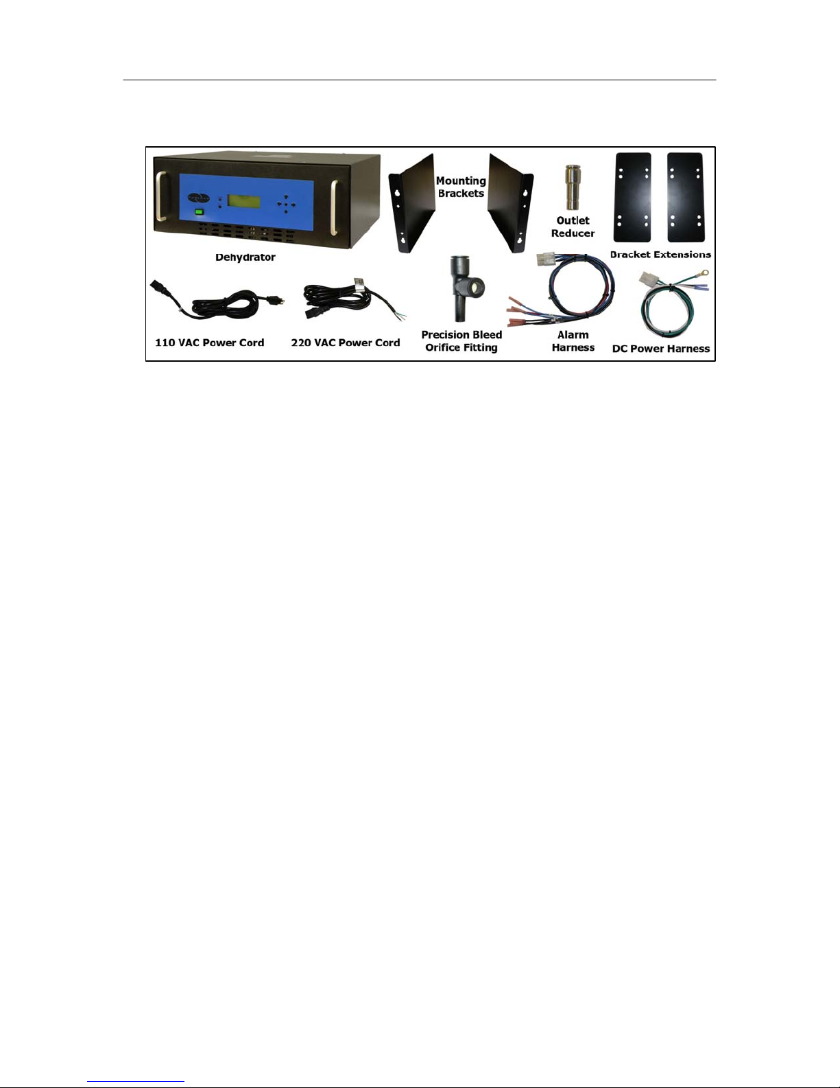
6.3 Included Contents
(1) P200W2 Series Dehydrator
(1) Installation Guide (not shown)
(1) User’s Guide (not shown)
(2) Mounting Brackets
(1) Package containing (for P200WA2 model):
Power Cord - (1) 110 VAC and (1) 220 VAC
(1) Package containing:
(2) Bracket Extensions (for 54.42 cm rack)
(1) Outlet Reducer (for 1/4” air supply line)
(1) DC Power Harness (for P200W2 and P208W2 models)
(1) Alarm Harness
(1) Precision Bleed Orifice Fitting
(1) Package of mounting hardware (not shown)
(1) Mini CD – Guides & SNMP Files
6.4 Required Tools and Materials
Medium Phillips screwdriver
7/16” wrench
Terminal crimpers
Box cutting knife
Page 12 of 82 P012213 – Rev. F
PUREGAS, LLC P200W2 Series Dehydrator User’s Guide
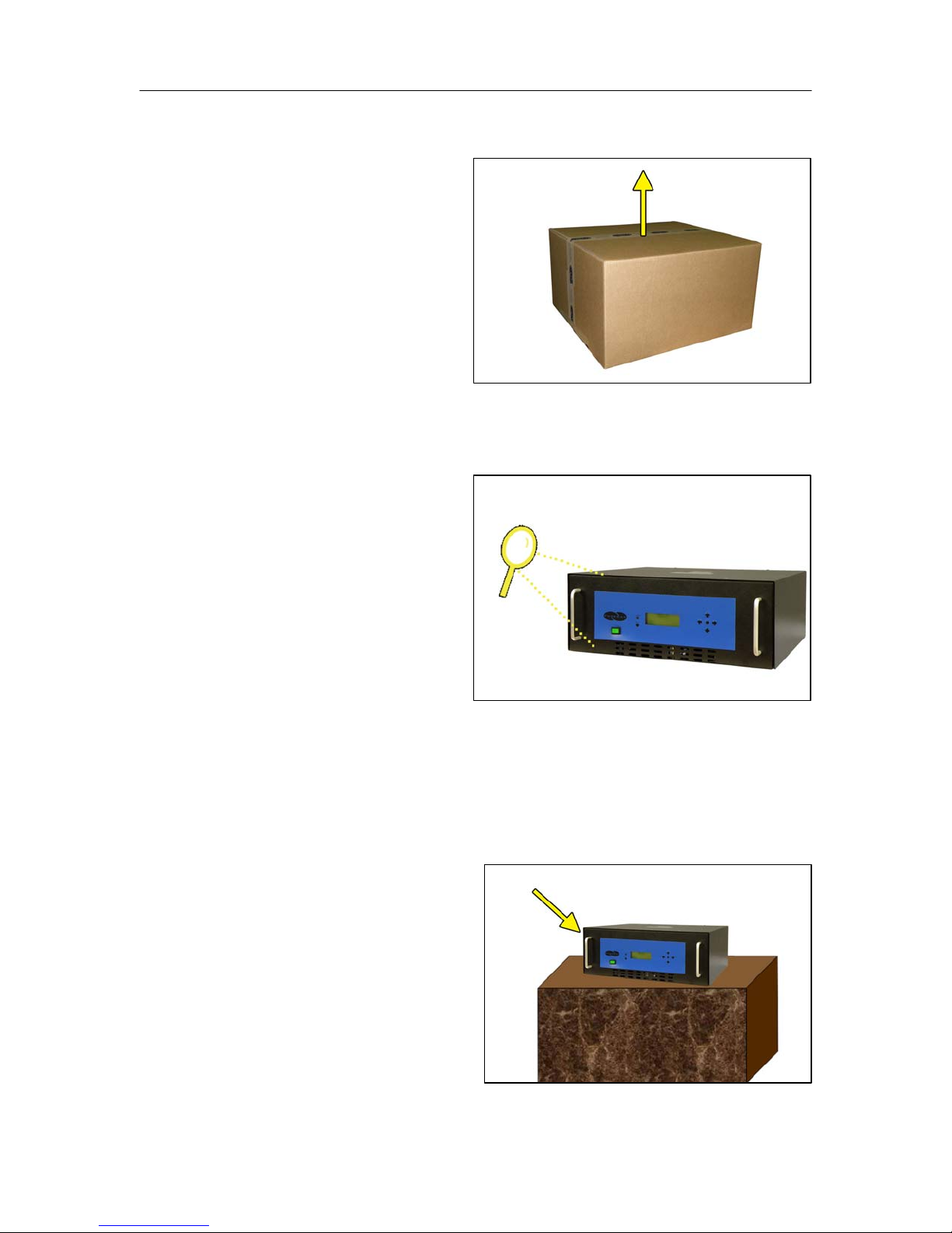
6.5 Installation Steps
6.5.1 Use a Box Cutting Knife to
open and remove the
Dehydrator and all contents
from packaging.
NOTE: If ANY SHIPPING
DAMAGE is detected, file a
claim with the shipping
company prior to continuing the installation procedures.
6.5.2 Inspect the Dehydrator for
any damage and verify
included contents
(Section 6.3 ).
NOTE: If ANY SHIPPING
DAMAGE is detected, file a
claim with the shipping
company prior to continuing the installation procedures.
6.5.3 Place the Dehydrator at the operating location:
For Bench Top Installation:
a. Place the Dehydrator on a
level surface.
Page 13 of 82 P012213 – Rev. F
PUREGAS, LLC P200W2 Series Dehydrator User’s Guide
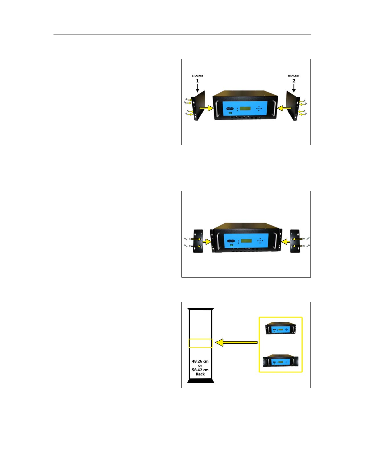
For Rack Mounted Installation:
a. Attach Mounting Brackets
to the Dehydrator with
mounting flanges facing
forward as shown.
Use Hardware A and
Phillips Head Screwdriver.
NOTE: Mounting Brackets
can be attached in a number of positions; front-to-back. Choose the
mounting position that meets your rack mounting requirement.
b. For installation on a
58.42 cm rack, attach the
Bracket Extensions to the
Mounting Brackets as
shown.
Use Hardware B, Phillips
Head Screwdriver, and
7/16” Wrench.
c. Install the Dehydrator on a
48.26 cm or 58.42 cm
Rack.
Use Hardware C and
Phillips Head Screwdriver.
Page 14 of 82 P012213 – Rev. F
PUREGAS, LLC P200W2 Series Dehydrator User’s Guide
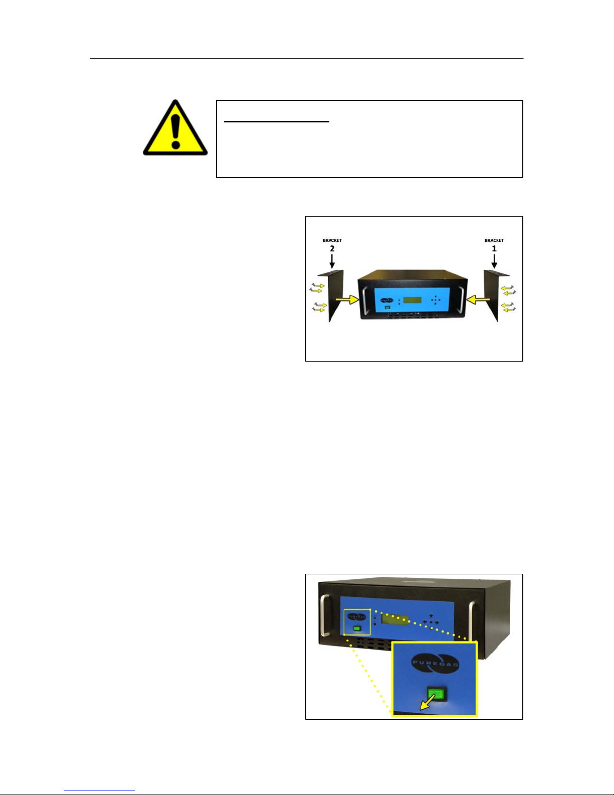
For Vertical / Wall Mounted Installation:
IMPORTANT!
a. Attach Mounting Brackets
to the Dehydrator with
mounting flanges facing
UP as shown.
Use Hardware A and
Phillips Head Screwdriver.
NOTE: Make sure the Mounting Brackets are attached in the forwardmost mounting position.
PUREGAS recommends keeping the area beneath a vertical
mounted dehydrator clear.
b. Install the Dehydrator on a wall with the Display Panel facing UP.
(Wall mounting hardware not supplied)
NOTE: To pre-drill a set of holes, horizontal spacing between bracket
holes is 46.67 cm on center.
6.5.4 Verify the Dehydrator is
powered OFF.
NOTE: POWER Button will
be in the Out position and
WILL NOT be illuminated
when power is OFF.
Page 15 of 82 P012213 – Rev. F
PUREGAS, LLC P200W2 Series Dehydrator User’s Guide
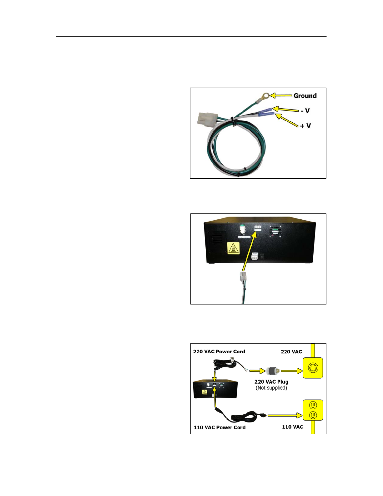
6.5.5 Connect Power to the Dehydrator:
For 24 VDC and 48 VDC Dehydrators:
a. Using Terminal Crimpers,
wire the DC Power
Harness to power supply:
WHITE: Positive Voltage
BLACK: Negative
Voltage
GREEN: Ground (Frame
or Power Supply Ground)
b. Connect the DC Power
Harness to the Power Port
on the back of the
Dehydrator.
For AC Dehydrators:
a. Plug in or wire the AC
Power Cord to power
supply:
BLACK: Line
WHITE: Neutral
GREEN: Ground
Page 16 of 82 P012213 – Rev. F

PUREGAS, LLC P200W2 Series Dehydrator User’s Guide
b. Connect the AC Power
Cord (110 VAC or 220
VAC) to the Power Port on
the back of the Dehydrator.
6.5.6 Power the Dehydrator ON.
NOTE: POWER Button and
Display Screen WILL be
illuminated when power is
ON. Otherwise, verify
wiring (Section 6.5.5 ).
NOTE: Compressor should
run briefly.
6.5.7 Remove the Outlet Port
Plug.
NOTE: Compressor should
run continuously once this
plug is removed.
6.5.8 Locate and familiarize
yourself with the Dehydrator
Control Buttons.
Page 17 of 82 P012213 – Rev. F
PUREGAS, LLC P200W2 Series Dehydrator User’s Guide
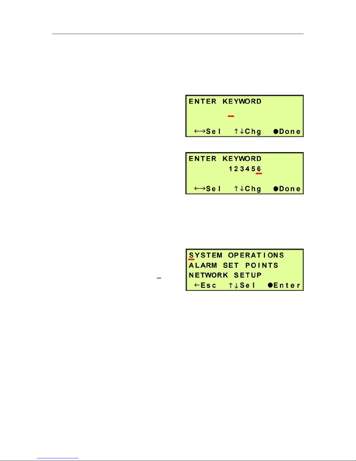
6.5.9 Press the Up () Arrow Button to access the Set Up Menu.
6.5.10 Enter the Keyword (default Keyword is 123456) –
6.5.10.1 Press the Left () &
Right () Arrow Buttons
to move the underscore
beneath the digit to change.
6.5.10.2 Press the Up () &
Down () Arrow Buttons
to change the value of the
selected digit.
6.5.10.3 Press the Function () Button when Done.
6.5.11 Press the Up () & Down ()
Arrow Buttons to move the
underscore beneath the “S” in
System Operations.
6.5.12 Press the Function () Button to Enter System Operations.
Page 18 of 82 P012213 – Rev. F
PUREGAS, LLC P200W2 Series Dehydrator User’s Guide
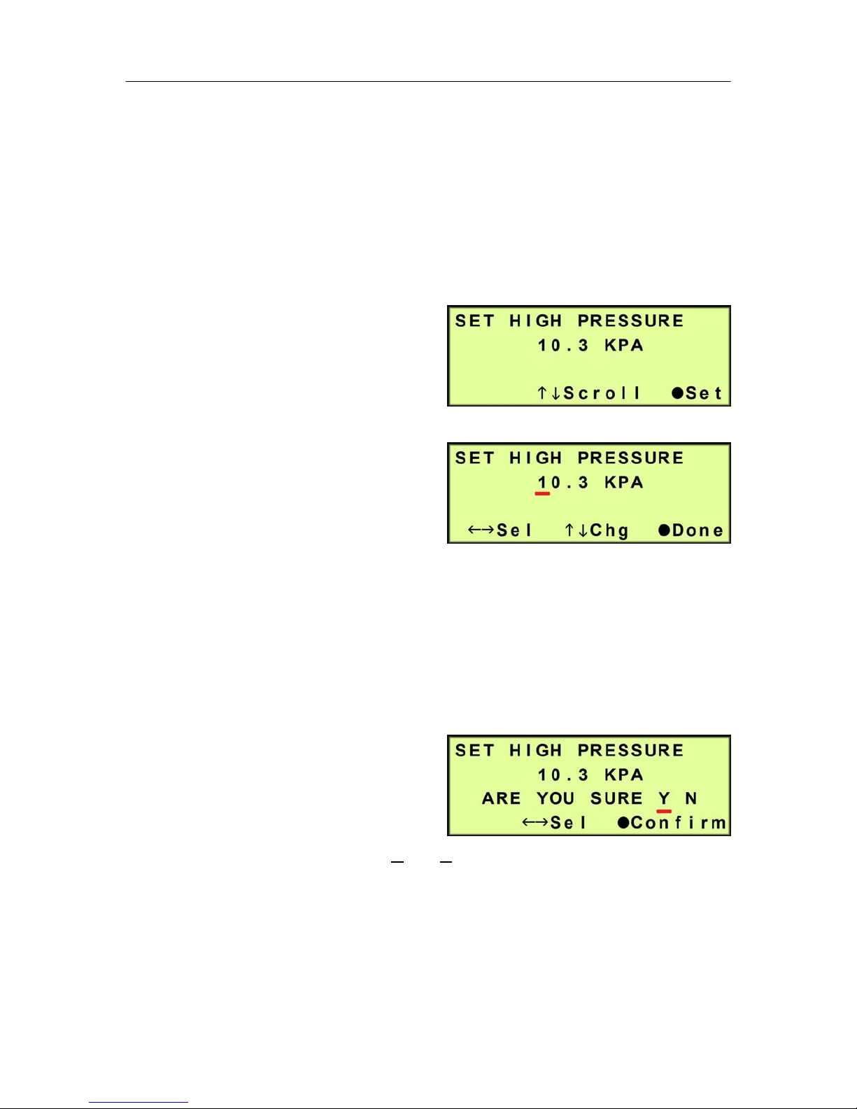
The System Operations Section is used to set the range for the system pressure.
When the system pressure reaches the High Pressure setting, the compressor will
turn OFF. When the system pressure reaches the Low Pressure setting, the
compressor will turn ON.
6.5.13 Set High Pressure (default setting is 10.3 KPa) –
6.5.13.1 Press the Function ()
Button to Set.
6.5.13.2 Press the Left () &
Right () Arrow Buttons
to move the underscore
beneath the digit to change.
6.5.13.3 Press the Up () & Down () Arrow Buttons to change the value of
the selected digit.
6.5.13.4 Press the Function () Button when Done.
6.5.13.5 Press the Left () &
Right () Arrow Buttons
to move the underscore
beneath the correct
confirmation choice (Yes or No).
6.5.13.6 Press the Function () Button to Confirm. This will lock in the new
setting value.
Page 19 of 82 P012213 – Rev. F
PUREGAS, LLC P200W2 Series Dehydrator User’s Guide
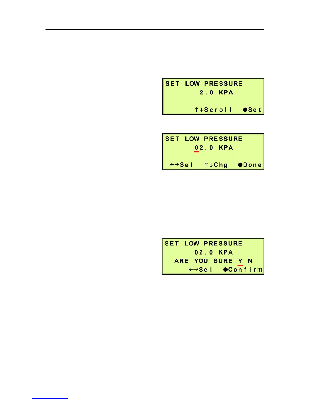
6.5.14 Press the Up () Arrow Button to access the Set Low Pressure screen.
6.5.15 Set Low Pressure (default setting is 2 KPa) –
6.5.15.1 Press the Function ()
Button to Set.
6.5.15.2 Press the Left () &
Right () Arrow Buttons to
move the underscore
beneath the digit to change.
6.5.15.3 Press the Up () & Down () Arrow Buttons to change the value of
the selected digit
6.5.15.4 Press the Function () Button when Done.
6.5.15.5 Press the Left () &
Right () Arrow Buttons
to move the underscore
beneath the correct
confirmation choice (Y
es or No).
6.5.15.6 Press the Function () Button to Confirm. This will lock in the new
setting value.
6.5.16 Press the Up () Arrow Button to access the Set Up Menu screen.
Page 20 of 82 P012213 – Rev. F
PUREGAS, LLC P200W2 Series Dehydrator User’s Guide
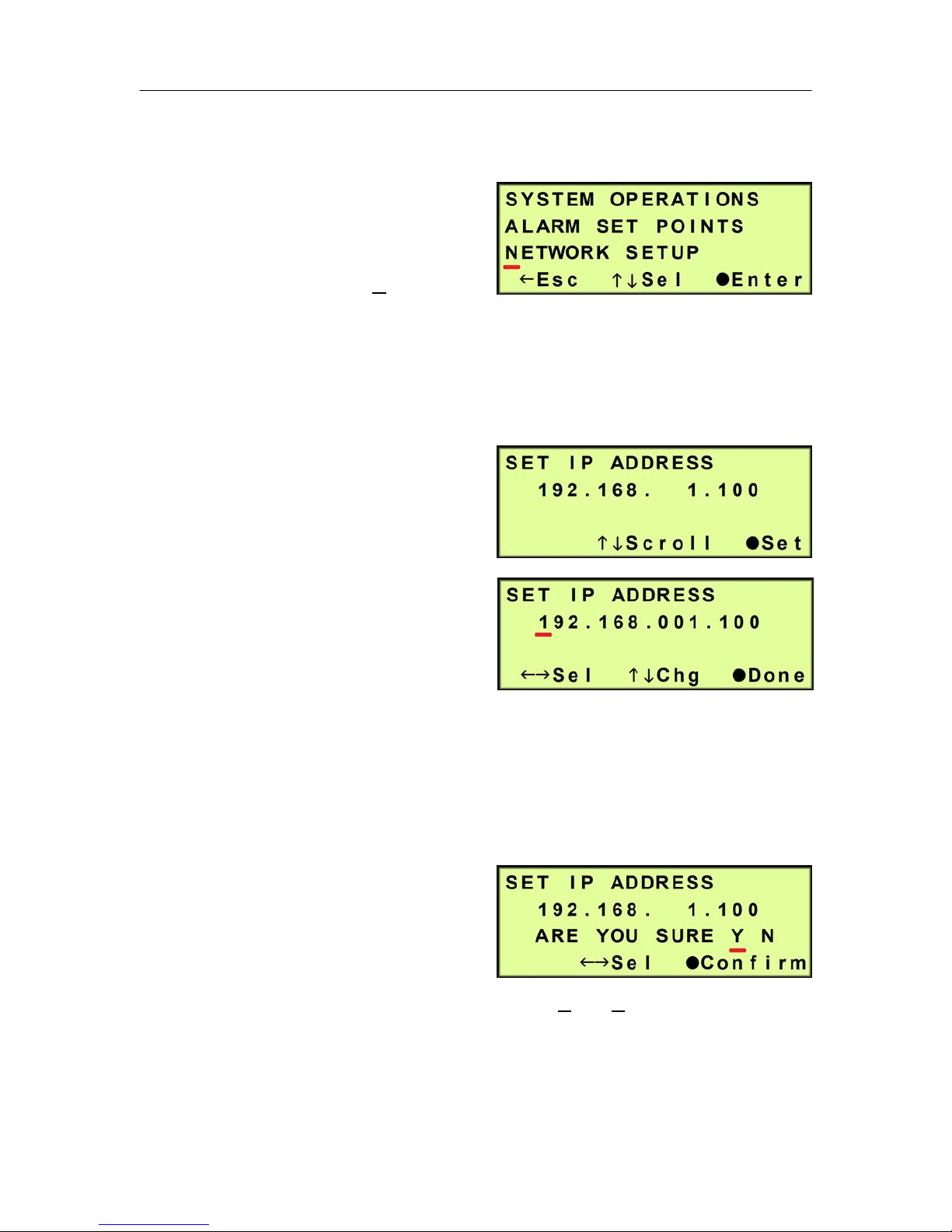
6.5.17 Set Network Configuration (if applicable) -
6.5.17.1 Press the Up () &
Down () Arrow Buttons
to move the underscore
beneath the “N” in
Network Setup.
6.5.17.2 Press the Function () Button to Enter Network Setup.
6.5.17.3 Set IP Address (default is 192.168.1.100) -
6.5.17.3.1 Press the Function
() Button to set the
IP Address.
6.5.17.3.2 Press the Left ()
& Right () Arrow
Buttons to move the
underscore beneath
the digit to change.
6.5.17.3.3 Press the Up () & Down () Arrow Buttons to change the
value of the selected digit.
6.5.17.3.4 Press the Function () Button when Done.
6.5.17.3.5 Press the Left ()
& Right () Arrow
Buttons to move the
underscore beneath
the correct confirmation choice (Yes or No).
6.5.17.3.6 Press the Function () Button to Confirm. This will lock in
the new setting value.
Page 21 of 82 P012213 – Rev. F
PUREGAS, LLC P200W2 Series Dehydrator User’s Guide
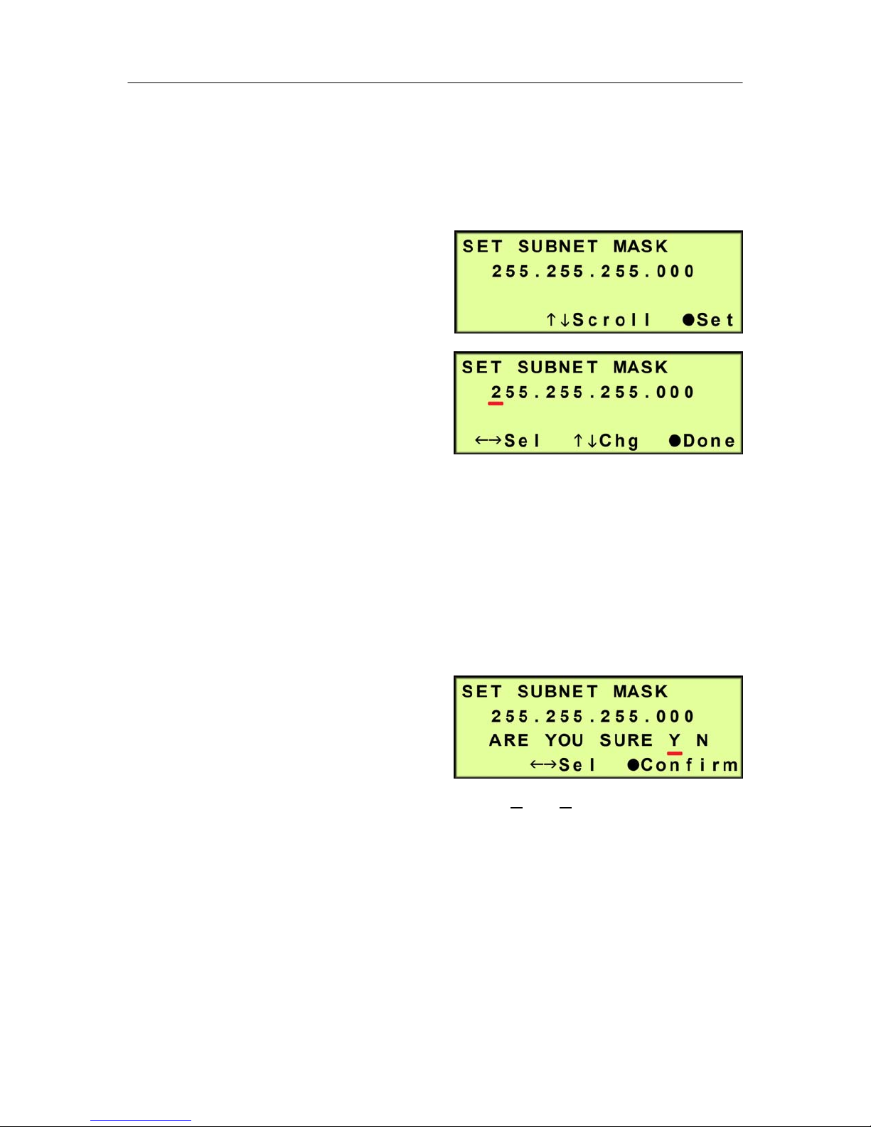
6.5.17.4 Press the Up () Arrow Button to scroll to the Set Subnet Mask
screen.
6.5.17.5 Set Subnet Mask (default is 255.255.255.000) -
6.5.17.5.1 Press the Function
() Button to Set the
Subnet Mask.
6.5.17.5.2 Press the Left ()
& Right () Arrow
Buttons to move the
underscore beneath
the digit to change.
6.5.17.5.3 Press the Up () & Down () Arrow Buttons to change the
value of the selected digit.
6.5.17.5.4 Press the Function () Button when Done.
6.5.17.5.5 Press the Left ()
& Right () Arrow
Buttons to move the
underscore beneath
the correct confirmation choice (Y
es or No).
6.5.17.5.6 Press the Function () Button to Confirm. This will lock in
the new setting value.
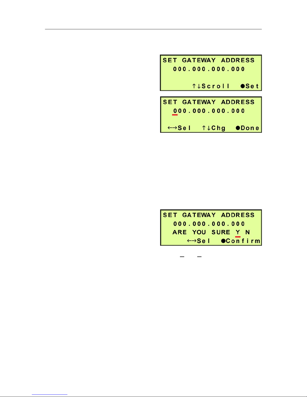
6.5.17.6 Press the Up () Arrow Button to scroll to the Set Gateway Address
screen.
Page 22 of 82 P012213 – Rev. F
PUREGAS, LLC P200W2 Series Dehydrator User’s Guide
6.5.17.7 Set Gateway Address (default is 000.000.000.000) -
6.5.17.7.1 Press the Function
() Button to Set the
Gateway Address.
6.5.17.7.2 Press the Left ()
& Right () Arrow
Buttons to move the
underscore beneath
the digit to change.
6.5.17.7.3 Press the Up () & Down () Arrow Buttons to change the
value of the selected digit.
6.5.17.7.4 Press the Function () Button when Done.
6.5.17.7.5 Press the Left ()
& Right () Arrow
Buttons to move the
underscore beneath
the correct confirmation choice (Y
es or No).
6.5.17.7.6 Press the Function () Button to Confirm. This will lock in
the new setting value.
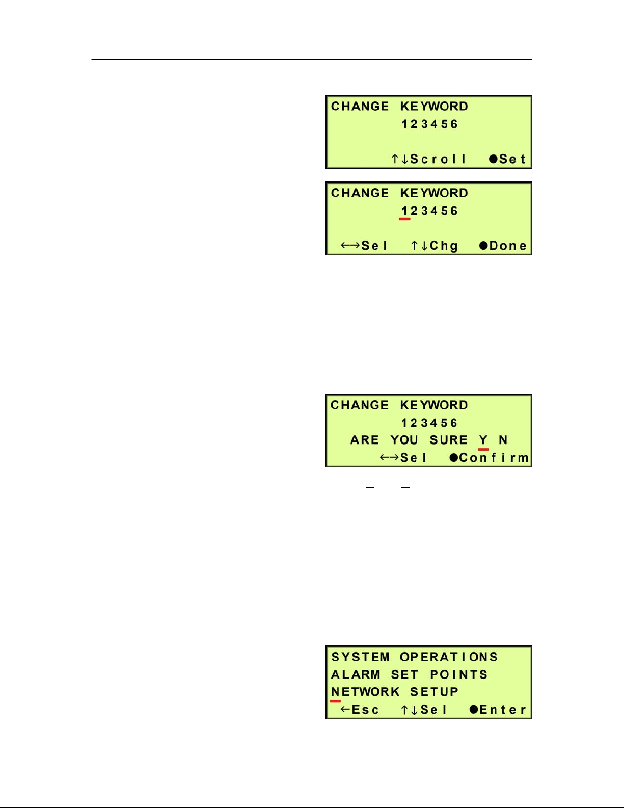
6.5.17.8 Press the Up () Arrow Button to scroll to the Change Keyword
screen.
Page 23 of 82 P012213 – Rev. F
PUREGAS, LLC P200W2 Series Dehydrator User’s Guide
6.5.17.9 Change Keyword (default is 123456)
6.5.17.9.1 Press the Function
() Button to change
the Keyword.
6.5.17.9.2 Press the Left ()
& Right () Arrow
Buttons to move the
underscore beneath
the digit to change.
6.5.17.9.3 Press the Up () & Down () Arrow Buttons to change the
value of the selected digit.
6.5.17.9.4 Press the Function () Button when Done.
6.5.17.9.5 Press the Left ()
& Right () Arrow
Buttons to move the
underscore beneath
the correct confirmation choice (Yes or No).
6.5.17.9.6 Press the Function () Button to Confirm. This will lock in
the new setting value.
6.5.17.10 Press the Up () Arrow Button to scroll to the Set Up Menu
screen.
6.5.18 Press the Left () Arrow
Button to Escape from Set Up
Menu and return to the
information screens.
Page 24 of 82 P012213 – Rev. F
PUREGAS, LLC P200W2 Series Dehydrator User’s Guide
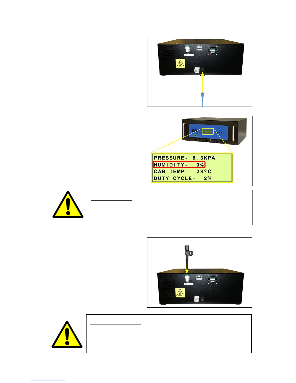
6.5.19 Connect a Network IP
cable to the UTP Port on the
back of the Dehydrator (if
applicable).
6.5.20 Let Dehydrator run until
the Humidity is 5% or below.
(May take 15 – 20 minutes).
NOTE: Press the RESET
Button if Dehydrator goes
into SHUTDOWN.
6.5.21 Connect the Precision
Bleed Orifice Fitting to the
Dehydrator Outlet Port
Fitting.
WARNING!
DO NOT CONNECT THE DEHYDRATOR TO THE SUPPLY LINE
UNTIL THE HUMIDITY READING IS 5% OR LESS.
Page 25 of 82 P012213 – Rev. F
IMPORTANT!
Installing the Precision Bleed Orifice Fitting will allow
Dehydrator to have a constant flow preventing high humidity.
 Loading...