

1
Thank you, and Congratulations on your purchase of The PureEffectTM ULTRA-UC Water Filtration
System Featuring: Our All-Natural FluorSorbTM Anti-Fluoride, Wide-Spectrum Anti-Radiation,
SuperBlockTM Anti-Chemical, KDF55® Heavy Metal Filtration and Natural Alkalization Technologies.
INSTALLATION INSTRUCTIONS
IMPORTANT! - BEFORE YOU START:
-Ensure there is a pressure regulator installed and is in proper working order before
proceeding. At no time should the filter housings be subject to more than 75PSI (most
common PSI range is between 40-75). You should contact a licensed plumber if you are not
able to check this on your own. Excessive water pressure could cause damage to the system
and water to leak out. Failure to follow proper installation instructions voids all
warranties and liabilities.
- The system should be installed where it is protected from freezing temperatures and
direct sunlight. Do not install the system where if would cause damage if leakage occurred.
1. ❏ Unpack your system, remove and set aside cartridges (by unscrewing chambers) and
inspect system for any transportation damage. If damage is found, please contact us right
away.
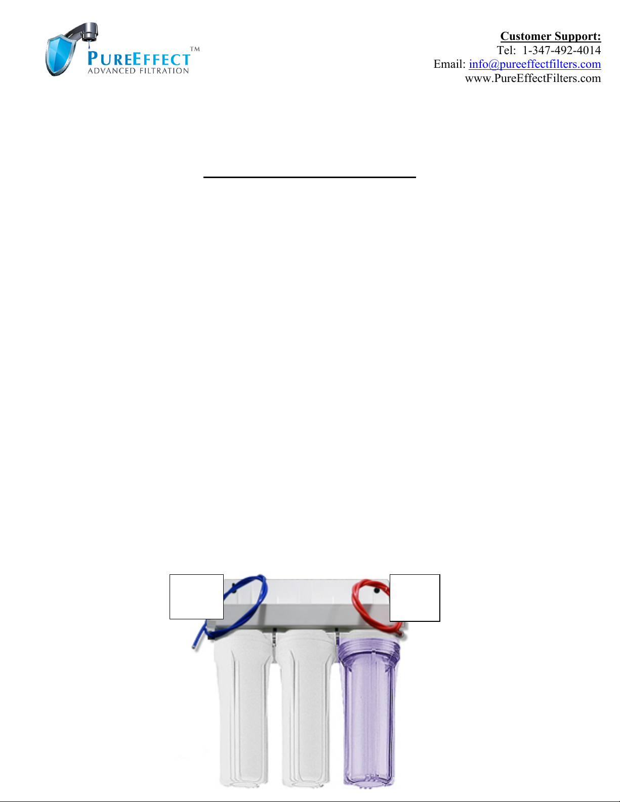
2. ❏ Find the individually wrapped White Elbow, also find the RED tubing with the
second white elbow attached. Locate the words “IN” and “OUT” on the unit’s water
connection ports. Screw the elbow with RED tube into the “IN” port and the additional
elbow, into the “OUT”. Note: The white elbow attached to the red tubing is outfitted with
a built-in flow restrictor to ensure optimal 0.5gpm water flow, which helps for greater
contaminant absorption. Please ensure this elbow is always connected on the input side
of the unit, even if you ever change tubing.
Customer Support:
Tel: 1-347-492-4014
Email: info@pureeffectfilters.com
www.PureEffectFilters.com
Red
Input
Blue
Output
2
3. ❏ Turn-Off Cold water supply via your Shut-Off Valve (Angle Stop) or water supply to
whole house. Note: It may be necessary to turn off the hot water supply as well.
4. ❏ Disconnect your existing connection(e.g. Riser Tube) from the cold water Angle Stop.
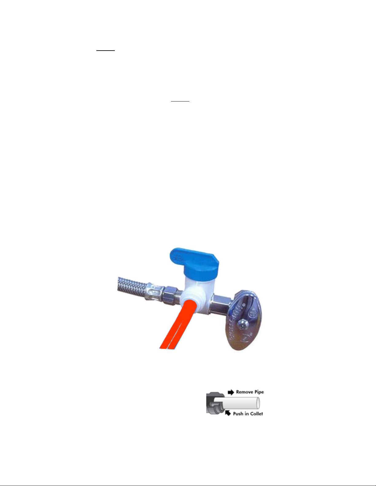
5. ❏ Connect the provided John Guest® Angle Stop Adapter Valve to the cold water Angle
Stop, see example pictured below. Note: Applying Plumbers Tape on the threading can
help with any leaks.
a. Reconnect your Existing Riser Tube to the Angle Stop Adapter Valve.
b. Position unit where you’d like, and ensure that the blue filter faucet and red water
input tubing will adequately reach the unit. Hang the filter system under the sink at
least 4” above floor (to allow for removal of chambers for cartridge changes).
c. Push-in the available end of the ¼” Red “IN” tube into the ¼” output port of the
Angle Stop Adapter Valve until it “pops-in” as far as it can go.
(If additional filtered water output connections are desired, e.g. fridge-water
Supply/Ice-maker connections, etc… please ask us about adding a ¼” 2-way
splitter to your unit’s output port).
6. ❏ Install the provided dedicated faucet into the sink. (See instructions on next page).
** To Disconnect
the tube from
connection:
! Angle Stop
(cold water)
! Angle Stop Adapter Valve
Riser Tube "
Red “IN” Tube "

3
FAUCET INSTALLATION INSTRUCTIONS
1. ❏ Use existing spray hose / soap dispenser hole, or Drill a 7/16” or 1/2” hole in sink top.
(We recommend using a carbide drill, use tape to protect sink top. If your sink is ceramic,
granite or some other fragile material, please consult with an expert to avoid cracking the
material during drilling).
2. ❏ Slide Metal Base Plate onto the threaded faucet shank, followed by Rubber Washer.
3. ❏ Insert Shank through the newly drilled or existing sink hole.
4. ❏ Under sink, Slide Locating
Washer, followed by Locking
Washer onto shank.
5. ❏ Thread the Brass Nut onto shank,
position faucet and tighten nut.
6. ❏ Insert the BLUE ¼” tube into the
“OUT” elbow of the filter unit.
(Ensure it pops in as far as it can go).
7. ❏ Ensure all connections are tight.
8. ❏ Proceed to Page 5 for cartridge
flush and leak test instructions.
Blue 1/4” Tubing (already connected
to faucet).
Existing / New Hole (drill
7/16” or 1/2” Diameter.)
Locating Washer
Brass Nut
Threaded Shank
Brass Nut
Locking Washer
Faucet
Metal Base Plate

4
GENERAL DIAGRAM
FLUORSORB
TM
CARTRIDGE
DUALCARB-SUPERBLOCK
TM
ANTIRAD-PLUS
TM
CARTRIDGE

5
INITIAL CARTRIDGE FLUSH AND SYSTEM LEAK TEST
IMPORTANT! – ENSURE CARTRIDGES ARE INSERTED IN CORRECT ORDER!
Note: You may want to place something under the unit to catch the
water which is released when you unscrew the last chamber for
Step D.
1. Remove shrink wrapping and insert the first two cartridges
only: SuperBlockTM cartridge into Chamber #1 and
FluorSorbTM cartridge into Chamber #2, screw the chambers
closed. Screw the last chamber closed also, it should be empty for
now.
A. Slowly turn on cold water, check newly installed faucet
and all connections for a watertight seal. *Note: you may hear a
slight “hissing” sound when the filter is working, this is normal
and is due to the built-in flow-regulator.
B. With your cold water on, gently turn the Handle on the
newly installed faucet to the side to allow water flow.
C. Check again for any leaks on all tubing and filter
connections to ensure watertight connection. If there are leaks at
input or output ports: ensure that the red and blue tubing is
pushed as far as it can go into the connecting elbows on the unit.
D. As the first water begins to flow, you may notice a small amount of grey carbon
dust pass through as the cartridges get flushed. Allow the cold water to run on full for 10
minutes then turn off faucet & shut off water supply to filter via the Angle Stop Adapter
Valve. Remove Shrink Wrapping and Insert the last cartridge (AntiRad-PlusTM) in
Chamber #3 and flush the entire system again for 15 minutes.
Note: First Water may be cloudy during few seconds of every use for about a week
as the Zeolite in this cartridge adapts and releases harmless mineral dust, this will subside
in about 1 week.
E. To Shut off the filter, turn off the faucet.
Congratulations! Your System is now ready for use.
THE FILTER SYSTEM IS DESIGNED FOR COOL - COLD WATER USE ONLY.
Do not allow hot water to run through the filter system.
Close
empty
until
Step D.
#2
#1
#3
Red
Input
Blue
Output
SuperBlockTM
FluorSorbTM

6
FOR CARE & OPTIMAL PERFORMANCE:
1. You may let the kitchen faucet run for a few seconds before using the filter, as this will
extend the filter life by flushing out any large sediment in the pipes.
2. Flush the system for 2 minutes when it hasn’t been used for 2 or more days.
3. Never run hot water through the filter, as the filtration process will not be effective. Use
only cold/cool water. Throughout usage you may notice the water level fluctuate in the
clear chamber, this is normal effect and does not interfere with proper filter function.
4. IMPORTANT! Whenever opening chambers to replace/remove cartridges, make sure to
first shut off the unit’s main water supply line.
5. Replace filter cartridges every 8 months* for consistently superior water quality. It is
highly recommended you lubricate the black rubber o-rings inside the housing with a
Food-Grade Silicone lubricant (we recommend “Novagard G662” from Amazon.com)
once a year to ensure leak-free performance.
*If there is high sediment amount in your water, your carbon block may clog sooner,
resulting in a reduction in water flow. In this case, only the first cartridge DualCarbSuperblockTM (carbon block) would need to be replaced sooner.
6. Every 6 months (recommended) or during cartridge changes: remove cartridges and
wipe the unit clean inside using Hydrogen Peroxide (do not get hydrogen peroxide inside
the filter cartridges), rinse with warm water, reinsert cartridges and flush with cold water
for 5 minutes.
7. Do not use system if your water pressure above 75PSI. In such a case, contact a plumber
to install a pressure regulator valve.

7
RETURN / EXCHANGE POLICY
1. If the filter arrived damaged, please call us immediately to get an exchange: 1-347-492-4014
2. If you choose to return the filter for any reason other than damage upon arrival, we will be happy to issue
a full purchase price refund or exchange within: 14 days of delivery date, minus shipping cost. The
return policy applies to water filter systems and any unused (sealed) filter media cartridges. If
cartridges have been opened and used, we will deduct the price of the cartridges from the refund, as they will
no longer be re-sellable.
3. If you decide to return past the 14-day return period, we will still accept the item for up to 30 days
from delivery date, however, there will be a reasonable 10% restocking fee applied. Please call us or send
an email to initiate the return process or if you have any further questions.
Once you’ve experienced your new system, feel free to share your positive experience by going to
our website product page and writing a review. ☺ Thank You! - The PureEffect Team
NO-HASSLE, 2-YEAR WARRANTY
SURVIVE & PROSPER, INC. dba PureEffectFilters.com, warrants it's water filter systems to be free of
defects in parts and workmanship for a period of: two (2) years from the date of purchase.
All our systems are made of high-quality components (not made in china) and are designed to last for many
years beyond the warranty period, but if any manufacturing defect is present, it will make itself know well
within the warranty period.
In the rare case that it should become necessary to repair or replace the filtration system or one of it's
components, please take a photo of the damaged part and email it along with your order # and a detailed
description of the defect to: info@pureeffectfilters.com or contact our Customer Service Department at: 1-
888-891-4821. We will handle your claim promptly, and as hassle-free as possible.
This warranty does not apply to defects resulting from action/s of the user such as: misuse, accidents,
improper installation, operation outside of specification (e.g. over the indicated PSI limit, exposure to direct
sunlight, freezing temps, UV light), improper maintenance or repair and unauthorized modification.
Survive & Prosper, Inc.’s total liability is limited solely to repair or replacement of the product. The
warranty set forth above is inclusive and no other warranty, whether written or oral, is expressed or implied.
 Loading...