

Pure Edge 3 X 100, 2 X 100, 4 X 100 Installation Instructions Manual
Doc # 904-PSB-2_3_4X100W-24VDC-RGB_06
1718 W. Fullerton Chicago, IL 60614
Ph: 773.770.1195 ● Fax: 773.935.5613
www.PureEdgeLighting.com ● info@PureEdgeLighting.com
© 2016 PureEdge Lighting. All Rights Reserved.
Installation Instructions for 2 X 100 / 3 X 100 / 4 X 100 Watt 24 Volt DC
RGB DMX LED Power Supply
SAVE THESE INSTRUCTIONS!
GENERAL INFORMATION IMPORTANT SAFETY INSTRUCTIONS
- RISK OF FIRE: This product must be installed by a
qualified electrician. Turn the power to the electrical box off
during installation. Read the "Important Safety Instructions"
before installation.
- NOTE: To avoid overheating the power supply, install it in a
ventilated remote location where air flows. Maintain proper
spacing among power supplies when multiple power
supplies are installed in the same remote location.
- This product is not suitable for wet locations. It is approved
for the use at any height above the finished floor.
- A typical installation is shown. Specific installation must be
in accordance with the local electrical codes.
- TO REDUCE RISK OF FIRE, it is important to wire the
power supply for the system as described in this
installation instruction.
- Load each power supply to MAXIMUM 100 Watts.
- Use CDP color dial or CTP color touch screen controller with
RGB LED soft strip.
- Do not install this power supply in a wet location.
- To reduce the risk of the system overheating and possibly
causing a fire, make sure all the connections are tight.
- Do not install *LED fixture closer than three inches or as
specified in the *LED fixture installation instructions to
curtains or similarly combustible materials. Keep insulation
at least 3" away from the enclosure.
- Turn the electrical power off before modifying the lighting
system in any way.
- The system is "ETL" listed for USA and Canada only when
all the products used are supplied by Edge Lighting.
* See LED fixture installation instructions for proper
placement.
100W, 24VAC LOW VOLTAGE WIRE SIZE CHART
WIRE LENGTH
3%
VOLTAGE
DROP
IN FT
WIRE SIZE
VOLTAGE AT END
OF THE WIRE
UP TO 31FT
14 AWG
23.28 VAC
32FT-49FT
12 AWG
23.29 VAC
50FT-81FT 82FT-124FT
10 AWG 8 AWG
23.28 VAC 23.28 VAC
1
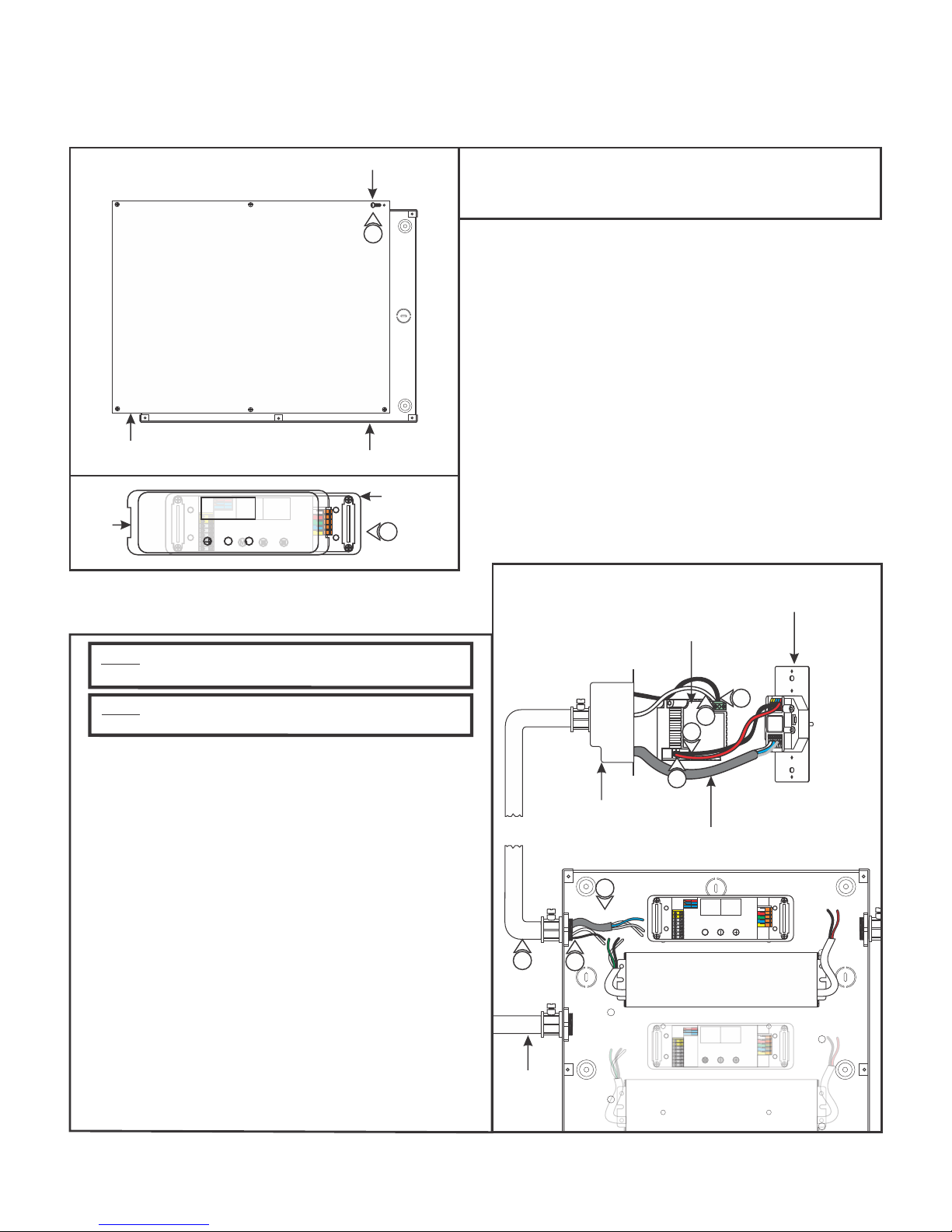
Using LED Power Supply with RGB Soft Strip & CDP or CTP
M
Controller
A
COVER
COVER
M
PHILLIPS SCREW
1
ENCLOSURE
DVR-RGB-60
2
NOTE: Use a deep double gang boxes to fit the controller
and controller power supply.
NOTE: Refer to the "Configuring and Operating Dim Wheel"
on pages 5 and 6 to properly operate the controller.
3: Connect one end of a red wire to the "VDC+" terminal of the
controller and the other end to the "+24VDC" terminal of the
controller power supply.
4: Connect one end of a black wire to the "Ground" terminal of
the controller and the other end to the "-24VDC" terminal of
the controller power supply.
1: Loosen the six Phillips screws on front of the power supply to
remove the cover.
2: Carefully pull off the cover from the DVR-RGB-60 driver.
B
CONTROLLER
CONTROLLER
POWER SUPPLY
6
5
4
3
ELECTRICAL BOX
DMX CABLE (BELDEN #9841)
5: Connect the white wire to the "N" terminal of the controller
power supply.
6: Connect the black wire to the "L" terminal of the controller
power supply.
7: Install conduits from the controller, main panel (line voltage),
and soft strip to the power supply enclosure.
8: Run the black and white line voltage wires coming from
the controller power supply to the power supply enclosure.
9: Run the proper size DMX cable (Belden #9841
recommended) with three data wires from controller to the
power supply box.
7
CONDUIT
9
8
POWER SUPPLY
2
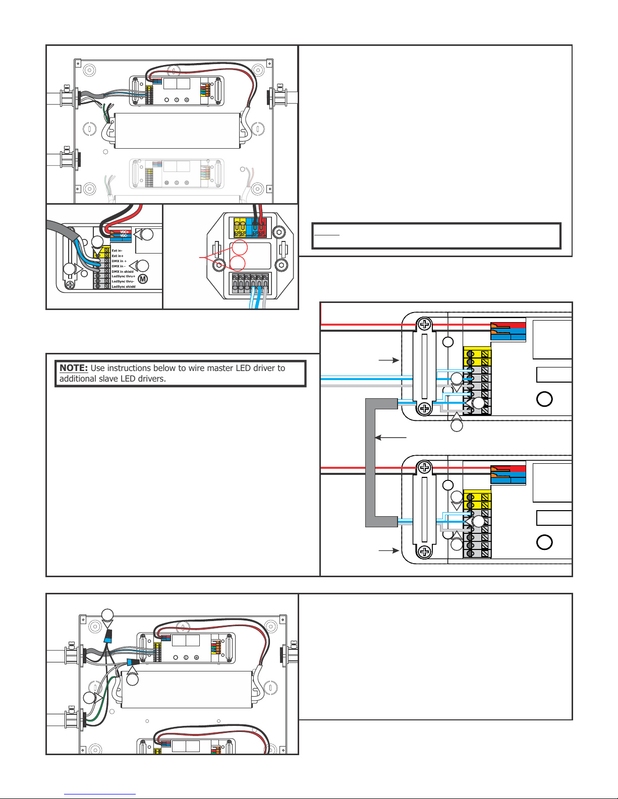
M
C
M
M
Ext in-
Ext in+
DMX in +
DMX in -
DMX in shield
LedSync thru+
LedSync thru-
LedSync shield
Driver
M
Ext in-
Ext in+
DMX in +
DMX in -
DMX in shield
LedSync thru+
LedSync thru-
LedSync shield
Driver
VDC+
VDC-
VDC+
VDC-
EXT in-
EXT in+
VDC-
VDC+
DMX in +
DMX in -
DMX in
shield
LEDSync
out +
LEDSync
out-
LEDSync
out shield
10: Install a red wire from the power supply to DVR-RGB-60
"VDC+" red terminal and a black wire from power supply
to DVR-RGB-60 "VDC-" blue terminal.
11: Connect one end of a data wire (blue with white stripes
wire) to controller "LEDSYNC OUT–" terminal. Connect the
other end into the DVR-RGB-60 "DMX in –" terminal.
POWER SUPPLY
12: Connect one end of a data wire (white with blue stripes
wire) to controller "LEDSYNC OUT+" terminal. Connect the
other end into the DVR-RGB-60 "DMX in +" terminal.
13: Connect one end of a data wire (bare shield wire) to
controller "LEDSYNC SHIELD" terminal. Connect the other
end into the DVR-RGB-60 "DMX in shield" terminal.
12
10
DO NOT
13
DVR-RGB-60
11
USE
CONTROLLER
NOTE: Use instructions below to wire master LED driver to
additional slave LED drivers.
14: Connect one end of a data wire (blue with white stripes
wire) to master LED driver "LEDSYNC OUT–" terminal.
Connect the other end into the DVR-RGB-60 "DMX in –"
terminal.
15: Connect one end of a data wire (white with blue stripes
wire) to master LED driver "LEDSYNC OUT+" terminal.
Connect the other end into the DVR-RGB-60 "DMX in +"
terminal.
16: Connect one end of a data wire (bare shield wire) to
to master LED driver"LEDSYNC SHIELD" terminal. Connect
the other end into the DVR-RGB-60 "DMX in shield"
terminal.
17: Repeat steps 14-16 for additional slave LED drivers.
E
19
NOTE: "DMX in+", "DMX in-", "EXT in+" & "EXT in-", controller
terminals are not used on controller.
D
MASTER LED
DRIVER
15
14
16
DMX CABLE (BELDEN #9841)
15
14
SLAVE LED
DRIVER
18: Run the line voltage power wires into the power supply.
19: Connect the hot power wire to the black power supply wire
and black controller power supply wire with a wire nut.
16
20
21
20: Connect the neutral power wire to the white power supply
wire and white controller power supply wire with a wire
nut.
21: Make sure the green transformer wire is grounded in
accordance with local electrical codes.
3
 Loading...