

Pure Blue H20 PB-TLRO4H50T Instruction Manual
REVERSE OSMOSIS
WATER FILTRATION SYSTEM
MODEL PB-TLRO4H50T
INSTRUCTION MANUAL
Pure Blue H20, LLC
13813 Monroes Business Park
Tampa, FL 33635 USA
www.pureblueh2o.com
(844) 787-3148 • (844) PURE-1-4-U
2015.06.30 #8739 PAW
Read this Manual BEFORE using this equipment.
This will not only familiarize you with the system, but it will help you determine the best location for
installation whether under a sink or in a remote location. Helpful diagrams follow. Keep this Manual for
future reference.
Operational Parameters
Installation must be in compliance with State and local plumbing regulations. Do not use with
microbiologically unsafe water or of unknown quality without adequate disinfection before or after
the system. System is intended to be installed using the cold water supply only.
Operating Temperatures: Maximum 100°F (37.8°C) Minimum 40°F (4.4°C)
Operating Pressure: Maximum 100 psi (7.0 kg/cm2) Minimum 40 psi (2.80 kg/cm2)
pH Parameters: Maximum 11 Minimum 2
Iron: Maximum 0.2 ppm
TDS (Total Dissolved Solids) < 1800 ppm
Turbidity < 5 NTU
Hardness
Hardness: Recommended hardness not to exceed 10 grains per gallon, or 170 parts per million.
Note: System will operate with hardness over 10 grains but the membrane life may be shortened. The
addition of a water softener may lengthen the membrane life.
Water Pressure: The operating water pressure in your home should be tested over, a 24 hour period to
attain the maximum pressure. If the incoming water pressure is above 80 psi then a water pressure
regulator is required. A booster pump is needed for incoming water pressure under 40psi.
Copper Tube: Reverse Osmosis water should not be run through copper tube as the purity of the water
will leach copper, which will cause an undesired taste in water and pin holes may form in the tube.
Note: Polytubing is recommended.
Maximum 10 Grains Per Gallon*
Maintenance of Filters for Model PB-TLRO4H50T:
Part Number Description Replacement
PB-TLRO4SEDT Stage 1 - Sediment Every 6 months
PB-TLRO4CB2T Stage 2 - Pre-Carbon Every 6 months
PB-TLRO4MC50T Stage 3 - RO Membrane Every 2-5 years
PB-TLRO4CB4T Stage 4 - Post-Carbon Every 1 year - Annually
21
Flow
REQUIRED TOOLS & MATERIALS
• Tape Measure • 1/8” & 1/4” Drill Bits • Phillips Head Screwdriver
• Pencil • Adjustable Wrench • Safety Glasses
• Utility Knife • Drill • Pan or Bucket
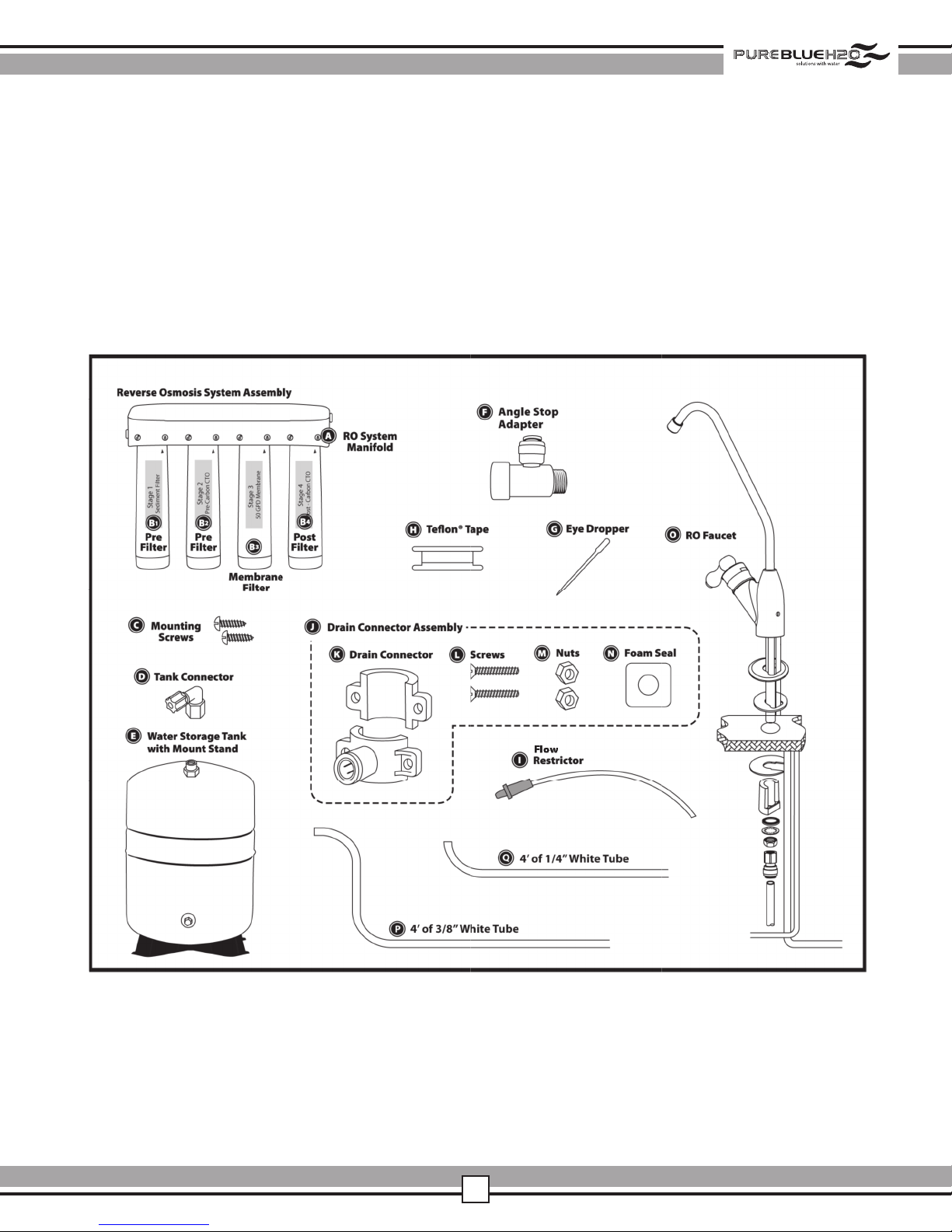
PACKAGE CONTENTS
22

PREPARE SITE FOR INSTALLATION
1 Prior to starting, close the cold water shut-off valve.
2
Temporarily place tank and filter assembly into cabinet to ensure adequate space and proper positioning.
Note: For filter installation, see page 5, STEP THREE, Filter Installation.
3 Remove tank and filter assembly from cabinet and set aside.
Note: The Filter System should not be installed in a location susceptible to freezing.
INSTALLATION OVERVIEW
There are seven easy steps to installing your RO unit. They are as follows:
Step 1 - Install Angle Stop Adapter (water source for filter system)
Step 2 - Install RO Drain Connector
Step 3 - Install RO Filter Assembly
Step 4 - Install Water Storage Tank
Step 5 - Install RO Faucet
Step 6 - Connect Tubing
Step 7 - System Start Up and Purge System
Notice: You must check and comply with all local plumbing codes.
If installing in a remote location, please refer to OPTIONAL REMOTE INSTALLATION PROCEDURE on page 9.
STANDARD INSTALLATION
2
3
!
WARNING
Be sure that all electrical appliances and outlets are turned off
at the circuit breaker before working in the cabinet area.
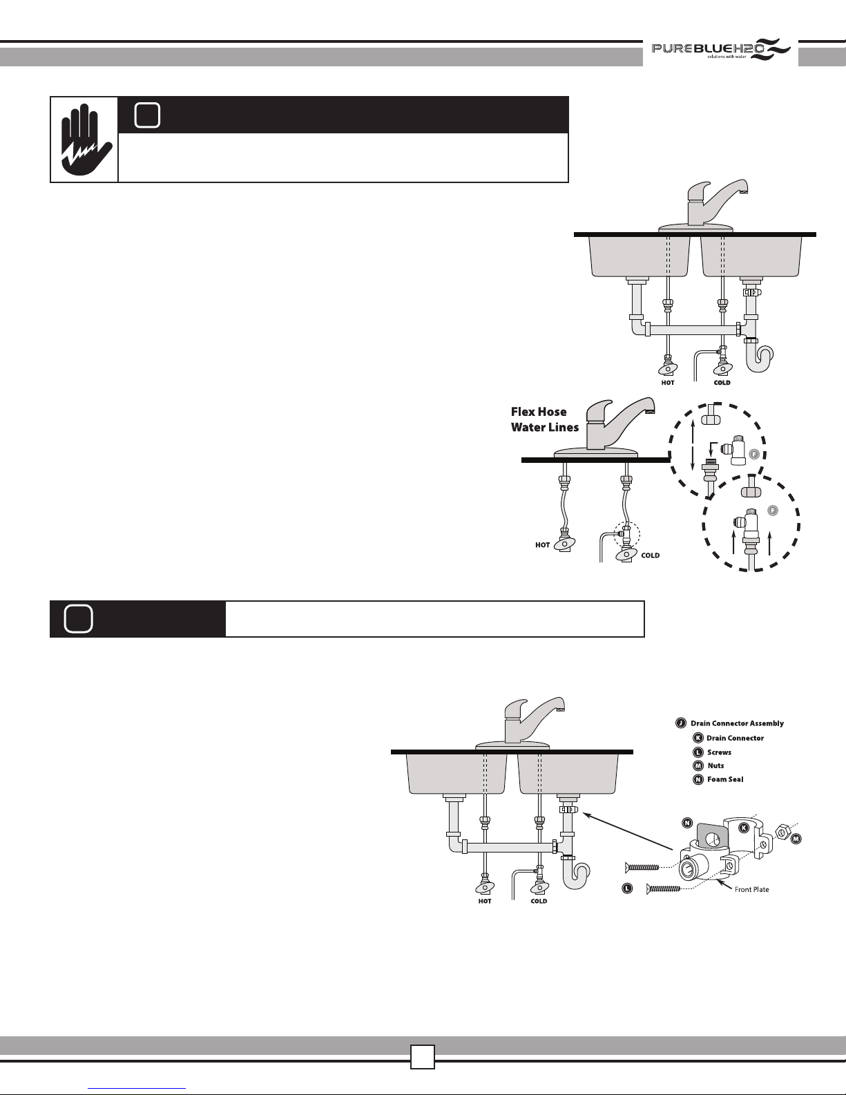
STEP ONE – INSTALL ANGLE STOP ADAPTER
1 Identify the cold water line in the sink cabinet.
Turn off the cold water supply to the sink.
2 Turn on the kitchen faucet to release pressure and
allow water to completely drain from the line.
3 Disconnect the cold water line from the cold water angle stop valve.
Note: You may need a plumber to shorten the supply line pipe
using a hacksaw or pipe cutter to accommodate the Kitchen
Faucet Adapter if pipe is rigid.
4 Screw on Angle Stop Adapter to cold water
angle stop valve. Do not over tighten Angle
Stop Adapter. (See diagram to the right)
5 Screw the cold water supply line to the male
thread side of the Angle Stop Adapter.
Caution: Do not over tighten.
STEP TWO – INSTALL RO DRAIN CONNECTOR
!
CAUTION
1 Identify drain outlet location.
2 Knock out center hole on foam seal (N).
3
Use hole in foam seal (N) as a template to
locate your drilling position above drain tap,
mark location with pencil.
4 At marked location, drill 1/4” hole through
wall of drain pipe. Be sure not to penetrate
opposite side of pipe.
5 Remove protective cover from back of foam
seal (N) and attach to front plate of drain
connector (K) in alignment with holes.
6 Begin to position the drain connector (K)
on sink drain pipe with Screws (L) and
Nuts (M), using your pencil (or a thin pen) in the drain connector (K) tube hole, to guide your location
over your drilled hole as you securely tighten Nuts (M) and Screws (L). Note: Remove pencil once
location is established.
Please wear safety glasses to protect eyes when drilling.
24
 Loading...