

PureAire Universal Gas Detector Instruction Manual
Universal
Gas Detector
Instruction Manual
PureAire Monitoring Systems, Inc.
1140 Ensell Road
Lake Zurich, Illinois 60047
Phone: 847-726-6000
Fax: 847-726-6051
Toll-Free: 888-788-8050
pureairemonitoring.com

Welcome to PureAire Monitoring Systems
I’d like to thank you for investing in our continuous life safety and process control toxic gas
monitoring systems.
PureAire offers an unbeatable combination of experience and innovation in solving the
safety and environmental needs of our customers. We’re capable of providing small
systems of a few points to a total multi-point turnkey computerized package.
PureAire’s proprietary sensor cell technology and state-of-the-art electronics are designed
to interface with the latest distributive or PLC based control systems. We believe that our
experience, innovative products and commitment to service will satisfy your specific
monitoring needs now and in the future.
Our growth is a result of our total commitment to supporting our customers. We’re
available 24 hours a day, 7 days a week to help you when you need us. Our 24 hour
Emergency phone number is 1-847-420-3814. We can provide field service, preventative
maintenance programs and training to your technicians in the operation of our equipment.
Our goal is to provide the best after sale service and support in the industry. That’s just
one way PureAire takes that extra step to ensure your complete satisfaction.
Thank you again for investing in PureAire Monitoring Systems for your monitoring needs
and I’m proud to welcome you to our family of valued and satisfied customers.
Sincerely,
Albert A. Carrino
President

Please Read Before Operating
The Universal Gas Detector has been designed to provide long-term reliable
performance. Read this “Guide to Operation and Installation” carefully. Installation,
maintenance, calibration and testing should be carried out by qualified personnel only.
The Universal Gas Detector requires 24 VDC regulated power. Please Do Not
connect the monitor to any voltage that exceeds 24 Volts DC. Please Do Not
Connect the monitor to any AC Voltage.
Always connect the sensor into the transmitter/readout before powering up the
detector. If you connect the sensor to the transmitter while powered, the detector will
reset and activate a complete 30 second startup which will activate the internal relays
and internal horn. If you have external horns and alarms connected to the detectors
internal relays, they will also activate!
The renewable sensor is filled with a liquid electrolyte. When storing the sensor cell
never store the sensor cell horizontal with the pressure compensation screw
positioned down or store the sensor cell upside down. This can cause the electrolyte to
leak from the sensor cell pressure compensation screw.
PureAire Renewable sensor cell has a 7-pin connector that connects to the transmitter
and remote sensor cable. NEVER twist the sensor when connected to the transmitter.
Twisting the sensor cell inside the transmitter connector will damage the 7-pin
connector.
The sensor cell is shipped with a jumper pin or battery on the 7-pin connector.
REMOVE this jumper before connecting to the transmitter.
When switching the gas sensor with a new universal transmitter, you must reenter the
Alarm 1 and Alarm 2 set points for the monitored gas into the Universal transmitter.
Only the calibration zero and span information stays with the sensor cell. All other
configuration information must be entered manually.
After initial power up of the Universal monitor or when connecting a new sensor cell to
the transmitter, It is required to perform a Zero adjustment. See Section 6.2.4

PureAire Monitoring Systems, Inc.
1
Table of Contents
1: Introduction .................................................................................................................................. 2
1.1 Key Features ................................................................................. 2
1.2 Component identification ............................................................. 3
2: Specifications ............................................................................................................................... 8
2.1 Performance Specifications .......................................................... 8
2.2 Gas Detection System ................................................................... 8
2.3 Signal Outputs .............................................................................. 8
2.4 Electrical Requirements ................................................................ 8
2.5 Physical Characteristics ................................................................ 9
2.6 System Default Factory Settings .................................................. 9
3: Installation .................................................................................................................................. 10
3.1 Site Requirements ....................................................................... 10
3.2 Mounting .................................................................................... 11
3.3 Wiring ......................................................................................... 12
3.4 Sensor Installation ...................................................................... 12
3.5 Initial Startup .............................................................................. 13
4: Normal Operation ...................................................................................................................... 14
4.1 Signal Outputs ............................................................................ 14
4.2 Instrument Faults ........................................................................ 14
4.3 Routine Maintenance Schedule .................................................. 15
4.4 Loss of Power Indicator .............................................................. 15
4.5 Alarm Reset ................................................................................ 15
5: Universal Gas Detector Programming ....................................................................................... 16
5.1 Joystick Operation ...................................................................... 16
5.2 Program Flowchart ..................................................................... 17
5.3 Entering the Password ................................................................ 21
5.4 Changing the User Password ...................................................... 22
5.5 Entering the Menus ..................................................................... 25
5.5.1 Set 4-20mA Loop .............................................................. 25
5.5.2 Set Formats ........................................................................ 27
5.5.3 Set Alarm Threshold Polarity ............................................ 29
5.5.4 Set Latching ....................................................................... 31
5.5.5 Resetting a Latching Alarm ............................................... 33
5.5.6 Set Alarm Delay ................................................................ 33
5.5.7 Set Zero Suppression ......................................................... 34
5.5.8 Set Alarm Thresholds ........................................................ 34
5.5.9 Set Alarm Hysteresis ......................................................... 36
5.5.10 Set Sensor Adjust............................................................. 38
5.5.11 Main Operation Mode ..................................................... 38
6: Maintenance & Cell Calibration ................................................................................................ 39
6.1.1 Sensor Recharge ................................................................. 39
6.1.2 Sensor Cell Replacement Parts ........................................... 44
6.2 Sensor Calibration Procedure ..................................................... 45
6.2.1 Sensor Gas Calibration ....................................................... 45
6.2.2 Sensor Calibration Equipment ............................................ 46
6.2.3 Sensor Calibration Procedure ............................................. 46
6.2.4 Setting Zero ........................................................................ 47
6.2.5 Span Calibration ................................................................. 47
7: Appendix .................................................................................................................................... 50
Rev. 4.07 June 6, 2018

PureAire Monitoring Systems, Inc.
2
1: Introduction
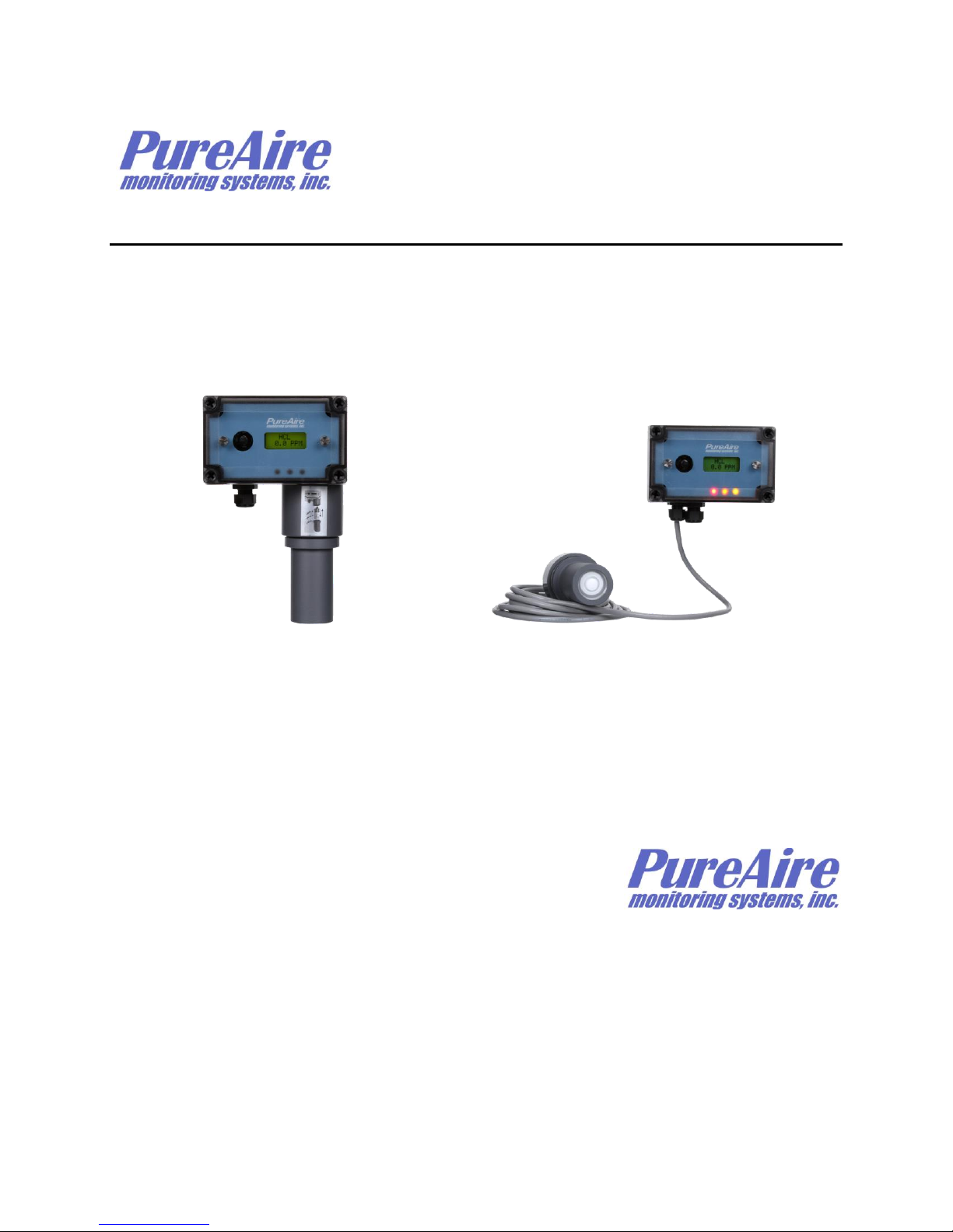
The Universal Gas Detector is a compact gas monitor designed for the continuous detection and
measurement of toxic and corrosive gas leaks. It consists of a generic transmitter/controller connected
to a dedicated, renewable gas sensor that automatically inputs the gas and measurement range. The
Universal is a single point monitor built into a polycarbonate UL listed enclosure suitable for indoor
use. It’s also available for NEMA 4X IP65 outdoor use when supplied without the built-in horn. It’s
designed to work as a stand-alone monitor or it can be connected to any PLC, programmable logic
controller or SCADA system.
The system has the following features:
▪ Universal transmitter, connects to any PureAire toxic & corrosive gas sensor
▪ Plug & Play sensor sets the gas and measurement range
▪ Sensor can be remote up to 30 feet from the transmitter
▪ Quick & simple remote sensor gas calibration; the sensor span stays with the sensor
▪ Digital display and built-in audible horn
▪ User selectable dual level alarm and system fault relays
▪ Renewable long life electrochemical sensor cell
▪ 24 VDC operation
▪ 4-20 mA output
▪ Supervised electronics monitors electronics with separate fault relay
▪ C UL listed Measuring Equipment E363306
NOTE: The Universal gas detector enclosure is NOT rated for Class 1,
Groups B, C & D
Ideal for continuously detecting gas leaks in confined spaces or areas where people are working the
Universal Gas Detector does not drift when the weather or temperature changes. Each system consists
of a long life renewable sensor with built-in microprocessor that stores gas, range and calibration
information. This manual covers the installation, operation, and maintenance of the Universal Gas
Detector.
1.1 Key Features
The Universal Gas Detector monitor incorporates a number of user-friendly features designed to
simplify installation, operation, and maintenance.

PureAire Monitoring Systems, Inc.
3
1.1.1 Renewable Gas Sensor with microcontroller
The heart of the system is a smart renewable sensor cell that’s programmed with the specific gas and
measurement range information. The renewable gas sensor automatically inputs the gas and
measurement range into the Universal transmitter. Simply plug the sensor into any Universal
transmitter and it’s ready to go.
1.1.2 Smart Electronics
The Universal Gas Detector incorporates a special electronic circuit that continuously monitors sensor
and transmitter operation. This smart circuitry alerts the user to sensor faults and other electrical
problems that may interrupt surveillance through the standard mA signal output signal and through the
fault relay.
1.1.3 Calibration
The PureAire Gas Sensor used with the Universal Gas Detector has a dedicated microcontroller built
directly into the sensor electronics which allows you to remove from it the transmitter for all routine
calibration and maintenance. Calibration data is directly entered into the sensor electronics and then
transferred to the transmitter once it’s plugged in. Calibration data stays with each sensor. See Section
6.2 for the calibration procedure
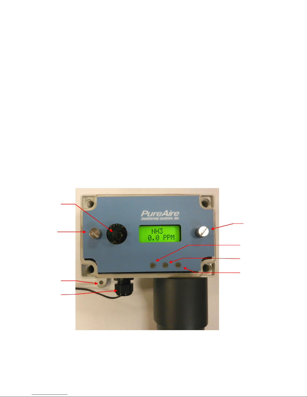
1.2 Component Identification
1.2.1 Front View Exterior
7
4
7
6
5
3
PureAire Monitoring Systems, Inc.
4
1. Digital Display — 3-digit backlit LCD digital display for showing the
type of gas detected and concentration in ppm, ppb or %.
2. Joystick — Used for selecting and adjusting the built-in menus. The joystick
is also used to select alarm levels, relay settings and resetting any latching
visual and audio alarms.
3. Cable Port — This is the opening in the transmitter housing for connecting
the 4-20 mA output and 24 VDC power cable.
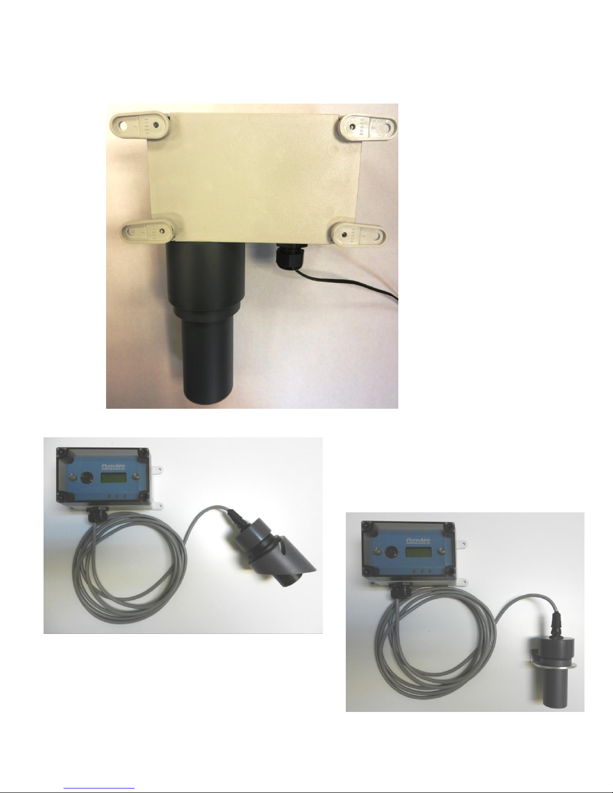
4. Sensor & Protector—The sensor can be mounted directly to the transmitter
case as shown. If the optional 30 foot remote sensor cable is used, it is
connected into a second cable port. See photo below
5. Mounting Feet — There are 4 feet used to mount the Universal Gas
Detector to a wall or other flat surface.
6. Transmitter Cover — A removable cover that protects the interior of the
transmitter.
7. Transmitter Cover Fasteners — There are 4ea. captive plastic screws
secure the transmitter cover in place.
8. Electronics Fasteners — There are 2ea. captive screws secure the
electronics to the enclosure
1.2.2 Front View Exterior
9. Alarm Indicators — 3 multi colored LED indicators for showing:
Alarm level 1 Orange LED
Alarm level 2 Red LED
Fault Alarm Yellow LED
2
8
5
3
1
8
9
Al 2
Al 1
Fault
PureAire Monitoring Systems, Inc.
5
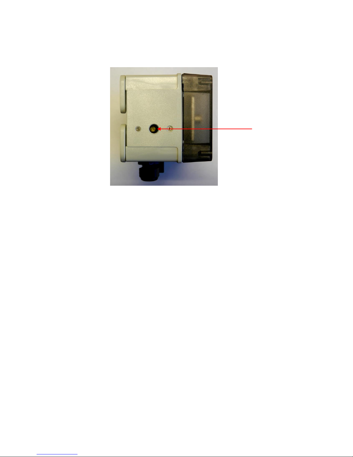
1.2.3 Side View Exterior with Audio Alarm
10. Audio Horn — This built-in horn is a 90dB high pitched audio sound that
will activate when the alarm levels go above the selected alarm thresholds.
The audio alarm is non-latching and will automatically turn off when the gas
levels go below the alarm thresholds
NOTE: The audio alarm is an immediate alarm. Gas concentration levels must
Recover below the alarm thresholds before the horn turns off. There is
no alarm delay function available.
11
PureAire Monitoring Systems, Inc.
6
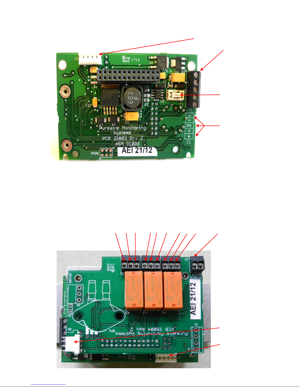
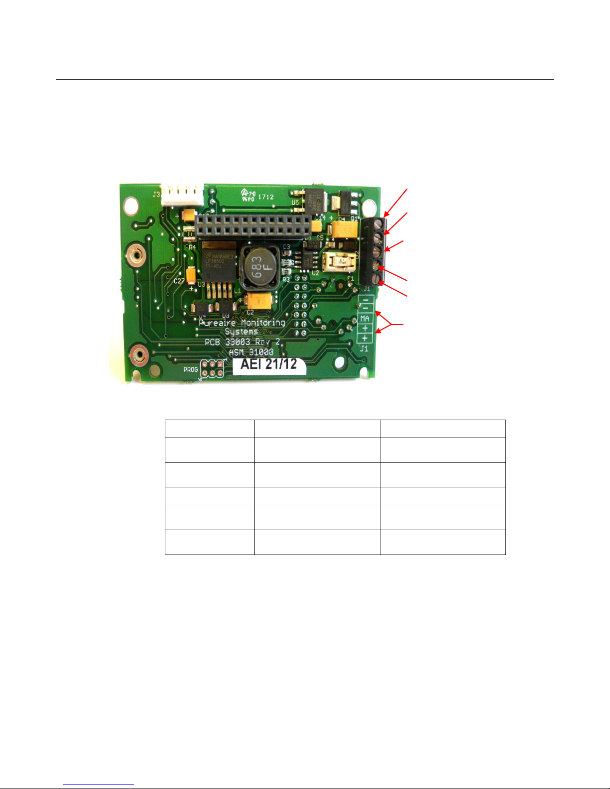
1.2.4 Transmitter Interior
1. Power Analog Terminal Block — This terminal block is where the 24VDC
power and 4-20 mA analog output connection is made.
2. Sensor Cell Connector — This connector is where the gas sensor is
connected.
1.2.5 Alarm Relay Board
1. Power
Analog output
Terminal Block
Fuse
(Field
replaceable)
Common
Common
mA output
+ 24 VDC
+ 24 VDC
Relay 2 Relay 1 Fault Relay Remote
NC C NO NC C NO NC C NO Reset
Horn Connector
Gas sensor
connector
2. Sensor cell
connector
PureAire Monitoring Systems, Inc.
7
1.2.7 Enclosure Mounting Feet
Mounting Feet
Can be oriented
in any direction
Feet can also be
removed for
mounting the
monitor flush
with a wall or
other surface
Universal Gas Detector with remote cable
connected to a duct
(Max cable length 30 feet)
Universal Gas Detector with remote
cable connected to the wall
(Max cable length 30 feet)

PureAire Monitoring Systems, Inc.
8
2: Specifications
NOTE: For our continual product improvement, all specifications are subject to change without notice.
2.1 Performance Specifications
Sensor Type: Renewable, electrochemical with built-in microcontroller
Response Time: T90 < 60 sec
Repeatability: ± 10% of reading
Fault Indicators: Loss of VDC power; analog signal drops to 0 mA
Electronics failure: Fault relay activated and analog signal drops to 2 mA.
Operating Temp: -30° to 134°F (-40° to +55°C); consult PureAire for lower or higher operating
temperatures.
Humidity: 0 to 95% RH; consult PureAire for sensors which can operate in 100%
condensing RH environments.
Environment: PSU only UL spec, Altitude 2000 m, Pollution Degree 3, Intended for Indoor Use.
UL / CUL listing: Measuring Equipment E363306
Enclosure: Polycarbonate UL listed designed for indoor use.
Optional, NEMA 4X, IP65 water resistant, without built-in horn
2.2 Gas Detection System
Universal Microprocessor electronics with built-in 3-digit backlit LCD display
Transmitter Two alarm relays, one fault relay and 4-20mA analog output. Joystick operated
menus.
2.3 Signal Outputs
Local Display: Digital display set for the proper gas and measurement range when the gas
sensor is plugged in. The range can be accessed via the joystick on the front
panel. In the measurement mode pushing the joystick down will scroll the gas
and range on the display. Push the joystick down again to stop the scrolling and
display the gas again.
Standard Analog Output: DC 4-20 mA
Optional Relay Output: Dual level user selectable alarm relays and one fault relay
Rated, 2amps @ 24VAC or 24VDC
2.4 Electrical Requirements
Power: 24 VDC external power. A regulated 24VDC power supply is required.
Consumption: Approximately 200mA

PureAire Monitoring Systems, Inc.
9
2.5 Physical Characteristics
Dimensions: 5.125 (W) x 3.15 (H) x 3.00 (D) inches; 130 x 80 x 76 mm
Weight: 1.1 pounds (0.5 kg)
Enclosure Type: General purpose; not intended for explosive atmospheres.
2.6 Universal Gas Detector Default Factory settings
The Universal Gas Detector is shipped with factory defaults for the alarm relay settings. The
following are the factory defaults:
Menu Function
Factory Default
Menu Defined
Set 4-20mA loop
The mA output is set at
the factory using a
calibrated Fluke meter.
Use this function to adjust the gas
detectors 4mA, (Zero) and 20mA,
(Span) to your PLC or distributive
control system.
Set Formats
LED and alarm relay
State
Alarm 1 = Normal
Alarm 2 = Normal
Fault = Normal
Do you want the relays to
energize, (normal) or de-energize,
(fail safe) when the alarm
activates?
Set Alarm Threshold
Polarity
Alarm 1 = Normal
Alarm 2 = Normal
Audio = Normal
Do you want to alarm at a level
higher, (normal) or lower,
(inverted) than the alarm
threshold?
Set Latching
Alarm 1 = Non-latching
Alarm 2 = Non-latching
Audio = Non-latching
Do you want the alarm to
automatically reset? (non-latching)
or do you want to manually reset
the alarm? (latching)
Alarm Delay
Alarm = 5 seconds
How long do you want to wait
until the relay alarms activate?
Zero Suppression
000 = 0.00ppm
Refer to section 4.5.6
At what level do you want the gas
monitor to display a reading?
Set Alarm
Thresholds
Alarm 1 = ½ TLV
Alarm 2 = TLV
Audio = ½ TLV
At what level do you want to
alarm?
Set Alarm Hysteresis
Alarm 1 = 0.0 %
Alarm 2 = 0.0 %
Audio = 0.0 %
For use when using the monitor
for control of valves and process.
See Section 5.5.9
Sensor Adjustment
No factory default
For use when dynamically gas
calibrating the monitor to a known
span gas. See Section 6.2
Manage Passwords
Factory default is 557
For use when changing the
password from factory default to a
new password of your choice.
PureAire Monitoring Systems, Inc.
10
3: Installation
3.1 Site Requirements
The Universal Gas Detector enclosure should be mounted in an area free of vibration and electrical
noise or interference. If possible, avoid areas with high temperatures or condensing humidity.
WARNING: The Universal Gas Detector is not designed for installation in
hazardous areas.
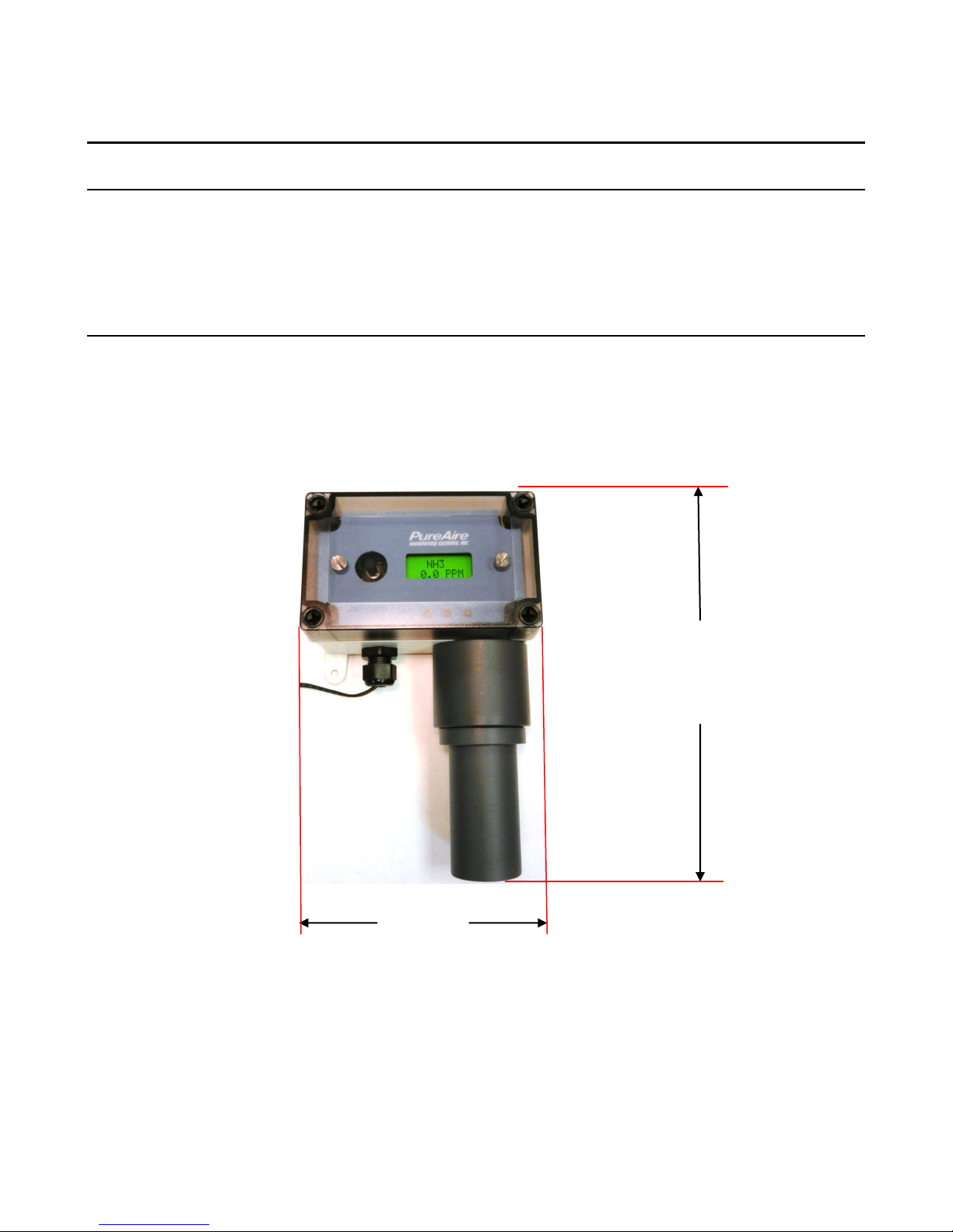
3.2 Mounting
3.2.1 Transmitter Enclosure
The Universal Gas Detector is designed primarily for wall mounting and should be installed at a height
convenient for operation, maintenance, and viewing of the instrument display. The following is a
drawing of the mounting dimensions.
3.2.2 Universal Gas Detector
The transmitter and sensor should be installed in a location where gas leaks are likely to occur or
where released gases may accumulate. It should be mounted no closer than 12 inches above floor level.
Airflow within the monitored area, the characteristics of the gas (lighter or heavier than air), and the
position of workstations and personnel should all be considered in determining the most suitable
installation location.
8.125”
5.125”
PureAire Monitoring Systems, Inc.
11
3.3 Wiring
The Universal Gas Detector requires a single, 3-wire shielded cable for analog output
and 24 VDC power input. A three-wire shielded cable; 3-conductor, 18 AWG stranded
General Cable E2203S.30.860, or equivalent is recommended for the connection. The
analog out and VDC power in connections are made on the terminal block inside the
transmitter housing.
These connections are made as follows:
Pin #
Connection
Description
-
Common (Signal Ground)
0V
-
Common (Signal Ground)
0V
MA
Signal Out
DC 4-20mA Output
+
Power
DC + 24V Input
+
Power
DC + 24V Input
NOTE: PureAire has added additional contacts for +24VDC power and Common to
accommodate additional wiring for remote horns and strobes
- Common
- Common
mA 4-20mA signal
output to PLC
+ 24VDC Power
+ 24VDC Power
Identification Legend

PureAire Monitoring Systems, Inc.
12
3.4 Sensor Installation
NOTE: The following applies to the Renewable Sensor cell mounted directly to the
Universal Gas Detector transmitter.
IMPORTANT: Be careful not to touch the membrane on the bottom of the sensor
during installation.
CAUTION: The target gas is factory programmed directly into the sensor cell. When
using multiple gases please install the correct sensor into the instrument will adversely
affect detection reliability and/or measurement accuracy.
1. Unpack the sensor cell from the plastic packing
2. Remove the shorting jumper from the sensor cell connector, located on the top of
the sensor
• IMPORTANT: Failure to remove the shorting jumper before connecting the
sensor cell to the transmitter will damage the sensor cell and void your warranty.
3. Insert the sensor cell into the cell holder on the universal transmitter. Carefully
rotate the sensor to align the male pins on the sensor cell to the female pins on the
sensor cell holder. Then push up to make the connection.
4. Install the sensor cell protector by rotating it clockwise to the cell holder on the
universal transmitter.
Must remove before
connecting sensor to
transmitter
Locating notch

PureAire Monitoring Systems, Inc.
13
3.5 Initial Startup
Once installation of the gas detector has been completed, it is ready for startup. The following
procedures should be performed before placing the instrument into operation:
1. Check the integrity of all wiring.
2. Apply 24 VDC power.
3. After power up, reset the zero. Refer to Section 6.2.4
The instrument should now be powered up. Upon power up, the Universal Gas Detector LCD displays
the PureAire logo and then starts a 30 second count down. During the entire warm-up period the
monitor will momentarily activate the internal relays and horn. If you have external horns and alarms
connected to the detectors internal relays, they will also activate. It will also output a 2 mA signal and
illuminate the fault LED. The LED will turn off at the end of the warm-up.
NOTE: After power up it is necessary to reset the zero. Refer to Section 6.2.4
NOTE: At initial power up, the internal relays and horn will activate momentarily. If you have
external horns and alarms connected to the detectors internal relays, they will also activate.
Gas Name
30 WARM
Universal
transmitter
Cell Holder
connector
Sensor Cell
Sensor Cell
Protector
1) Insert the sensor cell into
the cell holder on the
Universal transmitter.
Carefully rotate the
sensor to align the male
pins on the sensor cell to
the female pins on the
sensor cell holder.
NOTE: Align the locating notch
on the sensor cell with the notch
on the connector inside the Cell
holder
2) Push up on the sensor to
make the connection
inside the Cell holder
3) Attach the Sensor Cell
Protector to the
transmitter by twisting it
clockwise onto the Cell
holder

PureAire Monitoring Systems, Inc.
14
4: Normal Operation
The Universal Gas Detector is a single point monitor designed for the continuous detection and
measurement of ambient toxic and corrosive gas concentration levels.
4.1 Signal Outputs
The Universal Gas Detector outputs a continuous 4-20 mA analog signal proportional to the measured
concentration of toxic or corrosive gas. 4 mA represents 0 ppm and 20 mA represents full scale ppm
of the gas being detected. In the event of a system fault, a specific factory defined code will be
displayed on the local digital display. This code will indicate the exact nature of the system fault.
4.2 Instrument Faults
The Universal Gas Detector incorporates a number of self-checking features to
ensure reliable operation. In the event that a fault condition is detected, the
analog output signal is altered: A few common error codes are displayed in the
following table:
Condition
Analog Signal
**Supply Voltage Out of
Range Fault code 16
Analog output drops to 2 mA
Sensor cell cable cut
Analog output drops to 2 mA
***Communications Error
with Sensor Cell Missing
Fault Code 01
Analog output drops to 2 mA (0 mA on request)
Fault Relay activates
System Warm Up
Analog output drops to 2 mA
Fault Relay activates and turns off when system
is in the measurement mode
NOTE: If a Fault condition clears itself, (Yellow LED is no longer illuminated)
The Fault message will continue to scroll until manually cleared.
To clear the fault message, push the joystick down (- Minus)
NOTE: All system faults are displayed on the front panel. Each fault
has it’own specific code to identify the specific problem. Please
contact PureAire whenever a fault is displayed.
** When using your own power supply please insure that the voltage
is regulated to 24VDC +/- 0.5 volts. If the voltage is too low or high
you will activate a “Supply Voltage Out of Range fault and disable
the monitor.
*** If the monitor is in alarm Do Not unplug the Sensor cell. If the
monitor in in alarm and the sensor cell is unplugged, the alarms
and audible horn will remain activated. Resetting the alarms will
require a complete power down.

PureAire Monitoring Systems, Inc.
15
4.3 Routine Maintenance Schedule
Continuous gas detection systems depended upon to measure and detect hazardous gas leaks in the
workplace requires periodic maintenance to ensure proper operation. The frequency with which this
routine maintenance is required depends on the environment. The following table is intended to serve
as a general guideline for routine maintenance. The conditions in your application, as well as your
organization’s maintenance policies, will ultimately determine the best routine maintenance schedule
for your equipment. Routine Visual Checks
4.3.1 Recommended Routine Maintenance Schedule
Routine Visual Checks Every 6 - 12 months
* The LCD display should indicate the monitored gas and a 0ppm level.
The Alarm 1, Alarm 2 and Fault relays should not be illuminated. If
connected to a PLC or SCADA system, a 4mA signal will be output at
a 0ppm concentration.
Sensor Verification with span gas Every 6 - 12 months
4.4 Loss of Power Indicator
In the event the Universal Gas Detector loses 24VDC power, the 4-20 mA analog output signal drops
to 0mA. The LCD display will also display a blank screen.
4.5 Alarm Reset
Whenever the detector alarms are activated, the built-in alarm relays, panel mounted LED’s and audio
horn will also activate. When the relay settings are non-latching, the alarm relays, LED’s and horn
will automatically reset. If the relay settings are latching, then a manual reset of the alarms are
required. Resetting the alarms can be performed through use of the joystick or using the remote reset
function.
Joystick – You must enter the password to enter the reset function. After the password is entered and
accepted, push the joystick in; (enter) to reset the alarms.
Remote Reset – See section1.2.5. for location of the terminal block. The alarm relay board has a twopin connector for wiring to a remote switch. When connected to a switch, this remote reset will bypass
the joystick and a password will not be needed to reset the alarms.
NOTE: The gas levels must recover below the alarm thresholds before the horn can be
reset from the remote reset switch or joystick.
 Loading...