

PureAire TX-KE, TX-KP Instruction Manual

PureAire Monitoring Systems, Inc. 2/22/2000
0
Models TX-KE and TX-KP
Toxic Gas Transmitters
Instruction Manual
PureAire Monitoring Systems, Inc.
557 Capital Dr.
Lake Zurich, IL. 60047
Phone: 847-726-6000
Fax: 847-726-6051
Toll-Free: 888-788-8050
www.pureairemonitoring.com

PureAire Monitoring Systems, Inc. 2/22/2000
1
Table of Contents
1: Introduction ................................................................................................. 2
1.1 Model TX-KE ........................................................................................ 2
1.2 Model TX-KP ........................................................................................ 2
2: Specifications ............................................................................................... 5
2.1 Performance Specifications .................................................................... 5
2.2 Signal Outputs ....................................................................................... 5
2.3 Electrical Requirements ......................................................................... 5
3: Installation ................................................................................................... 6
3.1 Wiring ................................................................................................... 6
3.2 Sensor Installation.................................................................................. 9
4: Normal Operation ...................................................................................... 11
4.1 Concentration Display and Power Indicator Lamp ................................ 11
4.2 Routine Maintenance Schedule ............................................................ 11
4.3 Loss of Power Indicator ....................................................................... 12
5: Maintenance & Calibration ....................................................................... 13
5.1 Sensor Cell Removal and Installation ................................................... 13
5.2 Calibration ........................................................................................... 14
5.3 Electrolyte Replenishment ................................................................... 18
5.4 Sensor Calibration Kits ........................................................................ 23
PureAire Monitoring Systems, Inc. 2/22/2000
2
1: Introduction
This instruction manual provides installation, operation, and maintenance
information on PureAire Monitoring System’s Model TX-KE and Model TX-KP
gas detection systems. These systems may be used as either stand-alone detection
systems, linked to dedicated controllers, or connected to facility-wide
surveillance systems. The main difference between the TX-KE and TX-KP are
the components used to make them suitable for use in hazardous areas.
1.1 Model TX-KE
1.1.1 General Information
The Model TX-KE is an intrinsically safe instrument designed to continuously
detect and measure absorptive gases such as HCl, HF, and HCHO. It is suitable
for use in Class I, Division 1, Group B, C, and D hazardous areas when used with
a safety barrier installed outside the hazardous area. Standard features include:
• Intrinsically safe
• Digital or analog concentration display
• Rapid response
• One man, non-intrusive remote calibration
• Ideal for absorptive gases
• Plug-in diffusion-type sensor cell
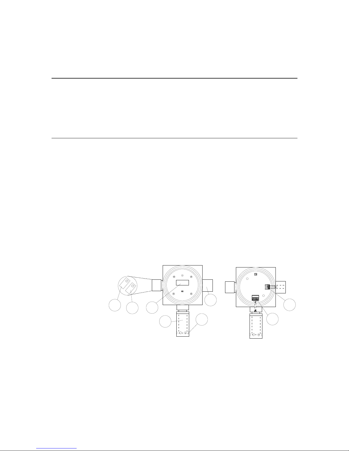
1.1.2 Component Identification
CN1
CN3
1 2 3 4
CMA+
Common
MA
+
TX-KE
Bionics Instrument Co., Ltd.
GAS DETECTOR
0
S
2
4
3
5
6
8
7
1
1. Concentration Display — A local analog or digital readout which displays
the measured concentration of the target gas.
2. Zero Potentiometer — This potentiometer is used to adjust the instrument’s
4 mA analog output signal to ensure that it is transmitting a 4 mA signal
when the instrument is reading a zero gas concentration. Note: Depending on
the gas sensor a clockwise or counterclockwise rotation increases the value; a
counterclockwise or clockwise rotation decreases the value.

PureAire Monitoring Systems, Inc. 2/22/2000
3
3. Span Potentiometer — This potentiometer is used to adjust the span
calibration of the system. It should only be adjusted when calibrating the
instrument. Note: Depending on the gas sensor a clockwise or
counterclockwise rotation increases the value; a counterclockwise or
clockwise rotation decreases the value.
4. Cable Inlet — This is a ¾ inch NPT opening in the transmitter housing for
connecting the 4-20 mA output and 24 VDC power cable.
WARNING: This connection must be made using an explosion-proof
cable gland or connector to seal the inlet if the TX-KE is being installed
in a hazardous area.
5. Cable Connection Terminal Block — The 4-20 mA output and 24 VDC
connections are made on this terminal block. See Section 3: Installation for
more information.
6. Sensor Connection Terminal Block — The sensor connection is made at
the factory on this terminal block.
7. Sensor Cover — This cover protects the gas sensor. It threads onto the
explosion-proof housing.
8. Gas Sensor — A plug-in electrochemical sensor designed to detect a specific
gas. It outputs an electrical signal proportional to the concentration of the
target gas which is translated by the instrument’s electronics and
subsequently displayed on the local readout and output as a 4-20 mA analog
signal.
1.2 Model TX-KP
1.2.1 General Information
The Model TX-KP is an explosion-proof instrument designed to continuously
detect and measure non-absorptive gases, such as CO, H2, and oxygen. It is
suitable for use in Class I, Division 1, Group B, C and D hazardous areas.
Standard features include:
• Explosion-proof
• Digital or analog concentration display
• 4-20 mA output
• Rapid response
• One man, non-intrusive remote calibration
• Low power consumption
• Ideal for non-absorptive gases
• Plug-in and disposable diffusion-type sensor cell

PureAire Monitoring Systems, Inc. 2/22/2000
4
1.2.2 Component Identification
CN1
CN3
1 2 3 4
CMA+
Common
MA
+
TX-KP
Bionics Instrument Co., Ltd.
GAS DETECTOR
0
S
2
4
3
5
6
8
7
1
1. Concentration Display — A local analog or digital readout which displays
the measured concentration of the target gas.
9. Zero Potentiometer — This potentiometer is used to adjust the instrument’s
4 mA analog output signal to ensure that it is transmitting a 4 mA signal
when the instrument is reading a zero gas concentration. Note: Depending
on the gas sensor a clockwise or counterclockwise rotation increases the
value; a counterclockwise or clockwise rotation decreases the value.
10. Span Potentiometer — This potentiometer is used to adjust the span
calibration of the system. It should only be adjusted when calibrating the
instrument. Note: Depending on the gas sensor a clockwise or
counterclockwise rotation increases the value; a counterclockwise or
clockwise rotation decreases the value.
2. Cable Inlet — This is a ¾ inch NPT opening in the transmitter housing for
connecting the 4-20 mA output and 24 VDC power cable.
WARNING: This connection must be made using an explosion-proof
cable gland or connector to seal the inlet if the TX-KP is being installed
in a hazardous area.
3. Cable Connection Terminal Block — The 4-20 mA output and 24 VDC
connections are made on this terminal block. See Section 3: Installation for
more information.
4. Sensor Connection Terminal Block — The sensor connection is made at
the factory on this terminal block.
5. Sensor Cover — This cover protects the gas sensor. It threads onto the
explosion-proof housing.
6. Gas Sensor — A plug-in electrochemical sensor designed to detect a specific
gas. It outputs an electrical signal proportional to the concentration of the
target gas which is translated by the instrument’s electronics and
subsequently displayed on the local readout and output as a 4-20 mA analog
signal.

PureAire Monitoring Systems, Inc. 2/22/2000
5
2: Specifications
NOTE: Due to our commitment to continual product improvement, all
specifications are subject to change without notice.
2.1 Performance Specifications
Sensor Type: Diffusion type electrochemical sensors:
TX-KE — Type DP and Type HP sensors
TX-KP — Type MP, KP, and TP sensors
Accuracy: ±5% full scale.
Operating Temperature: -20° to +50°C (-4° to +122°F).
2.2 Signal Outputs
Local Readout: Analog or digital display.
Analog Output: 4-20 mA.
2.3 Electrical Requirements
Power: 24 VDC.

PureAire Monitoring Systems, Inc. 2/22/2000
6
3: Installation
Both Model TX-KE and Model TX-KP gas detectors are designed for installation
in Class I, Division 1, Group B, C and D hazardous areas. They may be wall or
pipe mounted with the sensor pointing straight down. The instruments should
also be kept out of direct sunlight if possible.
3.1 Wiring
WARNING: The controller or DCS that supplies power to the TX-KP must be
turned off before opening the cover of the transmitter or connecting the
transmission cable. It is the user’s responsibility to confirm that no combustible
gas is present when opening the cover of the transmitter; failure to do so could
result in an explosion.
3.1.1 General
1. Remove the transmitter cover.
2. Remove the display unit. It is held in place by two Phillips head screws
which are marked with arrows.
3. Insert the three-wire 4-20 mA / 24 VDC power transmission cable through
the cable inlet.
WARNING: An explosion-proof cable gland or connector must be used to seal
the transmission cable inlet.
4. Connect the 4-20 mA / 24 VDC power transmission cable to the terminal
block.
5. Replace the display unit.
6. Replace the transmitter cover.
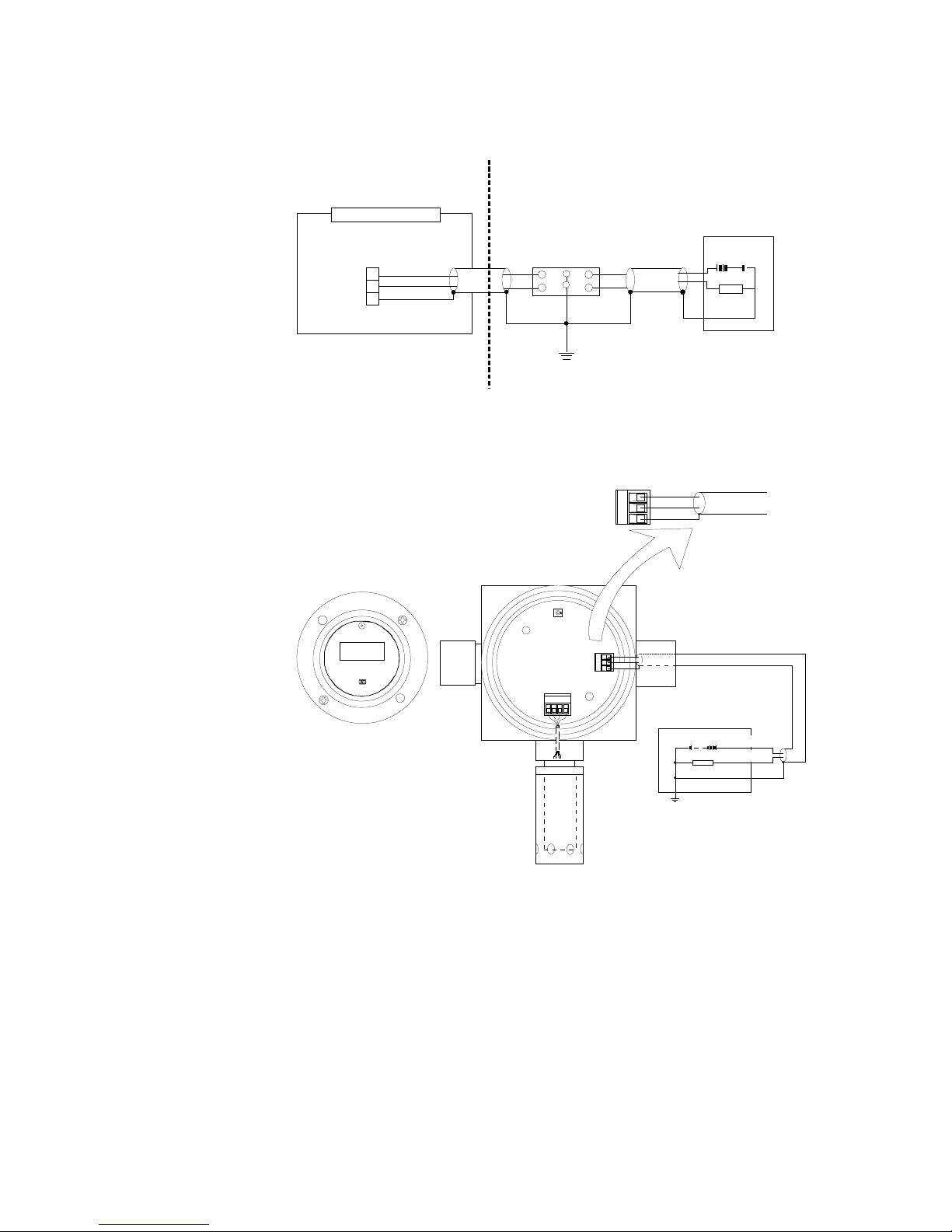
3.1.2 Model TX-KE (Intrinsically Safe)
CAUTION: If the Model TX-KE is installed in a hazardous area, it must be
wired through a safety barrier installed outside of the hazardous area. PureAire
Monitoring Systems recommends the use of the Model MTL788+ Safety Barrier
for intrinsically safe wiring.
The transmission cable should be connected to terminal block CN3 in the
explosion-proof housing. The white (+) wire connects to terminal #1, the black
(-) to terminal #2, and shield (S) to terminal #3.
IMPORTANT: Do not switch the polarity of the 24 VDC power line. The white
(+24 VDC) line must connect to terminal #1 and the black (0 VDC) power line
must connect to terminal #2.
PureAire Monitoring Systems, Inc. 2/22/2000
7
TX-KE Transmitter
Transmission Cable Connector
Shield
Hazardous Area
1
2
3
+
-
Intrinsically Safe Earth
Non-hazardous Area
DC-24V Power Supply
+
+
+
-
-
-
Shield
Shield
Shield
Max.
500
Ω
1
2
4
3
GND
LOAD
CN3
TX-KE Transmission Cable Wiring — Hazardous Areas
In the event that the TX-KE is installed in a non-hazardous area, it may be wired
as follows:
TX-KE
Bionics Instrument Co., Ltd.
GAS DETECTOR
CN1
CN3
1 2 3 4
LOAD
GND
DC 24V Power Supply
CMA
+
+ (White)
Shield
Shield
-
+
PC-1280RU
Transmission
Cable Inlet
NPT 3/4"
Transmission
Cable
3
2
1
Shield
- (Black)
+ (White)
- (Black)
TX-KE Transmission Cable Wiring — Non-Hazardous Areas
 Loading...