

PureAire 99088, 99072 Instruction Manual
Air Check Advantage
Methyl Bromide Monitor
Instruction Manual
Part number: 99088 (0-10ppm) 99072 (0-20ppm)
PureAire Monitoring Systems, Inc.
1140 Ensell Road
Lake Zurich, IL. 60047
Phone: 847-726-6000
Fax: 847-726-6051
Toll-Free: 888-788-8050
E-mail: info@pureaire.net
Web: Pureairemonitoring.com

PureAire Monitoring Systems, Inc.
1
Welcome to PureAire Monitoring Systems
I’d like to thank you for investing in our continuous life safety and process control toxic gas
monitoring systems.
PureAire offers an unbeatable combination of experience and innovation in solving the safety
and environmental needs of our customers. We’re capable of providing small systems of a few
points to a total multi-point turnkey computerized package.
PureAire’s proprietary sensor cell technology and state-of-the-art electronics are designed to
interface with the latest distributive or PLC based control systems. We believe that our
experience, innovative products and commitment to service will satisfy your specific monitoring
needs now and in the future.
Our growth is a result of our total commitment to supporting our customers. We’re available 24
hours a day, 7 days a week to help you when you need us. Our 24 hour Emergency phone number is
847-420-3814. We can provide field service, preventative maintenance programs and training
to your technicians in the operation of our equipment. Our goal is to provide the best after sale
service and support in the industry. That’s just one way PureAire takes that extra step to
ensure your complete satisfaction.
Thank you again for investing in PureAire Monitoring Systems for your monitoring needs and
I’m proud to welcome you to our family of valued and satisfied customers.
Sincerely,
Albert A. Carrino

PureAire Monitoring Systems, Inc.
2
President

PureAire Monitoring Systems, Inc.
3
This system has a built-in pyrolizer. The pyrolizer insulation temperature can reach
150 F and can cause burns if touched. Use Caution when working near the pyrolizer.
Read Before Operating
This gas monitoring system has been designed to provide long-term reliable performance. We recommend the
following basic precautions while installing, operating and maintaining this device.
Read this “Guide to Operation and Installation” carefully. Installation, maintenance, calibration and testing
should be performed by qualified personnel only.
Check if the power supply matches the specifications given in this guide and ensure that the system has been
connected properly. This monitor must be powered by a regulated 24VDC power supply.
Please insure the proper polarity. Reversing the polarity will damage the fuse on the drive PCB.
After power up, please let the system equilibrate a few hours before making any adjustments.
The methyl bromide monitor is designed for safety monitoring where normal use is defined as zero gas
concentration with an occasional excursion. If the monitor is continuously exposed to methyl bromide or if the
monitor is exposed to very high short term gas concentrations, it will require more frequent sensor cell
recharges, and complete pyrolizer filament and pump replacement.
Exposing the methyl bromide monitor to continuous levels of sulfur dioxide (SO
storage facilities will shorten the life of the gas sensor. This may require the need for annual gas sensor
replacement.
) from produce in cold
2
The pyrolizer filament is fragile and must never be disturbed once inside the pyro tube. Never twist the
filament inside the pyro tube.
PureAire Monitoring Systems, Inc.
557 Capital Drive
Lake Zurich, Illinois 60047
Ph: 888-788-8050
Ph: 847-726-6000
Fax: 847-726-6051
After Hours Hot Line: 847-420-3814
info@pureaire.net
www.pureairemonitoring.com

PureAire Monitoring Systems, Inc.
4
Rev 4.05 9/18/15
1: Introduction ........................................................................................ 5
1.1 Component Identification……………………………………… 6
2: Specifications .................................................................................... 11
2.1 Performance Specifications........................................................ 11
2.2 Gas Detection System ................................................................ 11
2.3 Signal Outputs ............................................................................ 12
2.4 Electrical Requirements ............................................................. 12
2.5 Physical Characteristics ............................................................. 12
2.6 Air Check Methyl Bromide Default Settings ............................. 13
3: Installation ........................................................................................ 14
3.1 Site Requirements ...................................................................... 14
3.2 Mounting .................................................................................... 14
3.3 Sensor Installation ...................................................................... 14
3.4 Wiring ........................................................................................ 15
3.5 Initial Startup ............................................................................. 16
Table of Contents
4: Air Check Methyl Bromide Programming .................................... 17
4.1 Control Panel Overview ............................................................. 17
4.2 Joystick Operation ..................................................................... 17
4.3 Program Flow Chart ................................................................... 18
4.4 Entering the Password ................................................................ 22
4.5 Changing the User Password ..................................................... 23
4.6 Entering the Menus .................................................................... 26
5: Maintenance & Calibration ............................................................ 37
5.1 Routine Maintenance Schedule .................................................. 37
5.2 Loss of Power Indication ........................................................... 37
5.3 Sensor Cell Removal and Installation ........................................ 38
5.4 Electrolyte Replacement ............................................................ 39
5.5 System Calibration ..................................................................... 43
6: Appendix ........................................................................................... 47

PureAire Monitoring Systems, Inc.
5
5
The Air Check Methyl Bromide Monitor is a compact extractive gas sampling system designed for the
continuous detection and measurement of toxic gas leaks. It is capable of sampling over distances of
up to 100 feet (33 meters).
The Air Check is a single point monitoring system built into an a Nema 4x water resistant housing that
may be wall mounted and is designed to require as little space for installation as possible.
The system has the following features:
24 VDC operation
Built-in pyrolizer
Integral digitally controlled sampling pump and flow system
Local digital display
User selectable dual level alarm and system fault relays
4-20 mA output
Renewable long life electrochemical sensor cell
Supervised electronics monitors sensor, pyrolizer and sample pump
NOTE: The Air Check Methyl Bromide enclosure is NOT rated for Class 1, Division 1
Groups B, C & D
1: Introduction

PureAire Monitoring Systems, Inc.
6
Mounting Tabs
(on each corner)
Cooling Fan
Cable Strain Relief
Front Cover
Cover fastening
screws
(on each corner)
Mounting Tabs
(on each corner)
Sample Exhaust
Sample Inlet
1.1 Component Identification
1.1.1 Overall System Composition
The Air Check Methyl Bromide Monitor may be integrated into the overall hazardous gas monitoring
system. As a result, it may be remotely located for the monitoring of process areas and other
environments where access to the instrument for maintenance or service may be restricted. It may also
be used as a stand-alone detection system.
Front Cover— This permits accessing the inside of the sample and control system.
Mounting Tabs— Adjustable feet designed to connect the methyl bromide enclosure to walls or other
solid surface. There is one on each corner of the enclosure.
Cover Fastening Screws— Captive Philips head plastic screws used to fasten the front cover to the
base of the methyl bromide monitor. There is one on each corner of the front cover.
NOTE: Please do not over tighten the screws as the Phillips head will strip.
Cable Strain Relief — This is the opening in the transmitter housing for connecting the 4-20 mA
output, 24 VDC power cable, and alarm relay wiring.
Sample Inlet — This serves as the connection for the incoming sample line.
Sample exhaust — This serves as the connection for the sample exhaust line.
Cooling Fan — This fan pushes air into the case for cooling. It exhausts on the top righ side of the
case
PureAire Monitoring Systems, Inc.
7
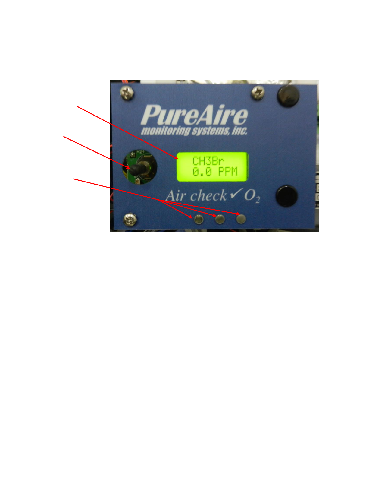
Local Digital
Display
Joystick
Alarm &
Fault
(LED’s)
AL 2 , AL 1
& Fault
7
1.1.2 Front View Control Panel
1. Local Digital Display — During normal operation, displays the name and concentration of the
target gas. Also displays alarm messages and programming/calibration menus and information.
2. Joystick — Used for selecting and adjusting the built-in menus for alarm threshold settings, relay
state, alarm delay etc.
3. Alarm & Fault LED’s — These LED’s illuminate when a gas concentration alarm or instrument
fault is detected.
NOTE – The flow rate is factory set and is continuously regulated via a built-in flow sensor.
Flow rate is factory set for sampling distances up to 100 feet. Field adjustment
cannot be performed.
PureAire Monitoring Systems, Inc.
8
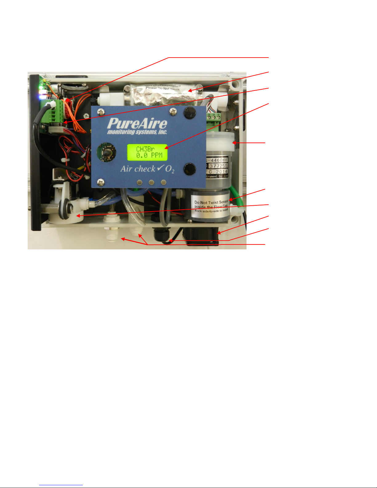
Main Power Connector
Pyrolizer Assembly
Pyro Filament Drive PCB
Control Electronics / Readout
Methyl bromide sensor cell
Flow chamber
Sample Pump
Cooling fan
Strain relief
Exhaust and Inlet
1.1.3 Internal View
1. Main Power Connector — Connector for 24VDC power input. See section 3: Installation for
more information.
2. Pyrolizer Assembly — Converts Methyl bromide gas into Bromine gas prior to presentation to
the gas sensor.
CAUTION - The pyrolizer insulation temperature is above 150 F and can cause burns if touched
3. Pyro Filament Drive PCB — Controls power to the pyrolizer filament and signals the main
control electronics if a fault occurs.
4. Control Electronics and readout — Controls the sample pump, converts the signal from the
sensor cell and sends information to the local digital display and analog /relay terminal block.
NOTE – The flow rate is factory set and is continuously regulated via a built-in flow sensor.
5. Flow Chamber — The converted gas from the pyrolizer is introduced to the gas sensor in this
chamber. Sample flow into the chamber is continually monitored. If the sample pump fails, the
system fault relay is activated.
6. Methyl Bromide Sensor Cell — A renewable electrochemical sensor cell. Typical life is 3 to 6
years under normal operating conditions.
7. Sample Pump — This internal sample pump is used to draw the gas sample from the area into the
pyrolizer and flow chamber.
8. Inlet & Exhaust — These are connections for the incoming gas sample and outgoing exhaust
sample
PureAire Monitoring Systems, Inc.
9
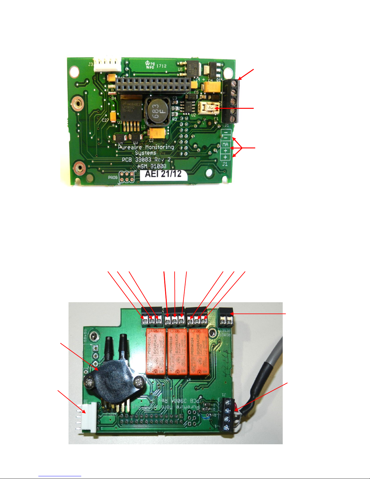
1. Power / Analog
output Terminal Block
Fuse
(Field replaceable)
Common
Common
mA output
+ 24 VDC
+ 24 VDC
9
Flow Sensor
Pump
Connector
Alarm Relay 2 Alarm Relay 1 Fault Relay
NC C NO NC C NO NC C NO
Remote
Reset
Sensor cell
connector
(terminated at the
factory)
1.2.5 Transmitter Interior
1. Power / Analog Terminal Block — This terminal block is where the 24VDC power and
4-20 mA analog output connection is made.
1.2.6 Alarm Relay Board
PureAire Monitoring Systems, Inc.
10
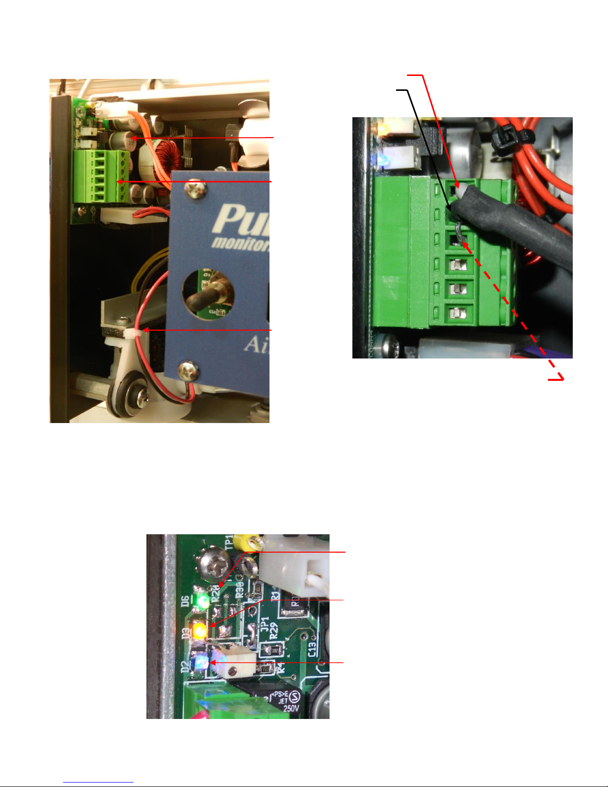
Main power connection
(Terminated by PureAire or
can be terminated by the
customer when using their
own power supply)
Status LED’s
Green Power LED.
Confirms Power is being supplied to
the monitor.
Yellow Status LED.
Confirms the filament drive board is
operational.
Blue Fault Status LED.
Flashes to indicate various system
faults.
When not in fault the Blue LED
remains illuminated continuously
Pump and Pyrolizer Drive Assembly
Pyrolizer
Drive Board
Main 24VDC
Power
Connector
Sample
Pump
+ 24VDC Pin 6
Common Pin 5
NOTE: DO NOT Remove the shorting
pin connected to pins 5 and 4.

PureAire Monitoring Systems, Inc.
11
11
2: Specifications
NOTE: Due to our commitment to continual product improvement, all specifications are subject to
change without notice.
2.1 Performance Specifications
Models: Air Check Methyl Bromide Monitor
Sensor Type: Renewable electrochemical cell. Field rechargeable.
Response Time: Within 60 seconds to T90.
Repeatability: ±10% of full scale.
Fault Indicators: Loss of VDC power (4 mA signal drops to 2, system fault alarm relay de-energizes);
Loss of sensor signal (local visual alarms, system fault alarm de-energizes);
Loss of sample pump (4 mA signal drops to 2, system fault alarm relay de-energizes)
Loss of Pyrolizer filament (4 mA signal drops to 2, system fault alarm relay de-energizes)
Operating Temp: 14° to 86°F (0° to +30°C); consult PureAire for lower or higher operating temperatures.
Humidity: Typically 20 to 95% RH;
Warranty: The warranty is limited to repairing or replacing the instrument or part thereof for a period
of one (1) year after shipment, when in our opinion, the repair or replacement is covered by
this warranty. Any defective equipment must be returned prepaid to the PureAire Monitoring
Systems, Inc. factory or service. Field service is not included. This warranty does not cover
components that are expendable or consumable in normal use and thus have an unpredictable
life such as batteries, fuses, sample pumps, filaments and sensor cell electrolyte & membranes.
2.2 Gas Detection System
Type: Proprietary renewable electrochemical gas sensor.
Sensor Life: 3 to 6 years under normal conditions.
Detectable Gas: Methyl Bromide Standard Range 0-10ppm *
*Consult PureAire for other available gas ranges.

PureAire Monitoring Systems, Inc.
12
2.3 Signal Outputs
Local Display: Digital display calibrated for Methyl Bromide. The range is stated on the serial number and can be
accessed via the joystick on the front panel.
Analog Output: DC 4-20 mA
Relay Output: Dual level user selectable alarm relays and one fault relay
Rated, 2amps @ 30VDC; 2amps @ 250VAC
2.4 Electrical Requirements
Power: 24 VDC external power. NOTE: Must be a regulated 24VDC Power Supply
Consumption: 2.0 amps.
2.5 Physical Characteristics
Dimensions: 10” W x 7.0” H x 7.0” D inches;
254 x 178 x 178 mm
Weight: 10 pounds (4.5 kg)
Enclosure Type: NEMA 4X wall mounted enclosure. Not for use in hazardous environments.

PureAire Monitoring Systems, Inc.
13
Menu Function
Factory Default
Menu Defined
Alarm Thresholds
Alarm 1 = 1.0ppm
Alarm 2 = 5.0ppm
At what level do you want to alarm?
Set Alarm Threshold
Polarity
Alarm 1 = Normal
Alarm 2 = Normal
Do you want to alarm at a level
higher, (normal) or lower, (inverted)
than the alarm threshold?
Alarm Delay
Alarm = 5 seconds
How long do you want to wait until
the alarms activate?
Zero Suppression
0.3ppm
At what level do you want to see the
initial gas concentration reading?
Set Alarm Hysterisis
Alarm 1 = 0.0 ppm
Alarm 2 = 0.0 ppm
For use when using the monitor for
control. It is recommended to set both
alarm hysterisis at 0.0ppm
Relay Latching
Alarm 1 = Non-latching
Alarm 2 = Non-latching
Do you want the alarm to
automatically reset? (non-latching) or
do you want to manually reset the
alarm? (latching)
Format Relay - LED
State **
Alarm 1 = Normal
Alarm 2 = Normal
Fault = Normal
Do you want the relays to energize,
(normal) or de-energize, (fail safe)
when the alarm activates?
13
2.6 AirCheck Methyl Bromide Default Factory Settings
The Air Check Methyl Bromide Monitor is shipped with factory defaults for the alarm relay settings. The
following are the factory defaults:
NOTE:
The built
in relay
settings
may be
changed
by the user
in the
field.
Refer to
Section
4.5
** NOTE:
The LED
indicators
on the
front panel
are
connected
directly to
the alarm
relays.
PureAire Monitoring Systems, Inc.
14
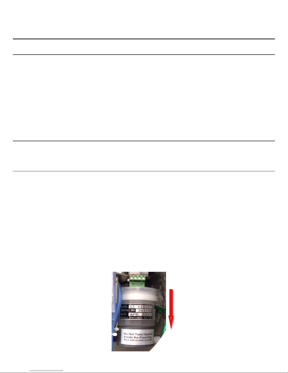
Insert the sensor cell
into the flow
chamber by pushing
the sensor cell down
until it seats inside
the O-ring.
Never twist the
sensor cell inside
the flow chamber.
3.1 Site Requirements
The Air Check Methyl Bromide monitoring system should be mounted in an area free of vibration and
electrical noise or interference. If possible, avoid areas with continuous high temperatures or relative
humidity.
The unit should be installed in a location where gas leaks are likely to occur or where released gases
may accumulate. Airflow within the monitored area, the characteristics of the target gas (lighter or
heavier than air), and the position of workstations and personnel should all be considered in
determining the most suitable installation location.
Allow sufficient space around the instrument to permit access for maintenance and calibration.
NOTE: The Air Check Methyl Bromide Monitor is NOT designed for installation in hazardous
areas.
3.2 Mounting
The Air Check is designed primarily for wall mounting and should be installed no closer than 36 inches
(915 mm) above floor level. If mounted outdoors, keep direct sunlight off of the enclosure.
3: Installation
3.3 Sensor Installation
IMPORTANT: Be careful not to turn the sensor or touch the membrane on the bottom of the sensor
during installation.
CAUTION: The target gas is factory programmed and cannot be adjusted in the field. Failure to
install the correct sensor in the instrument will adversely affect detection reliability and/or
measurement accuracy.
1. Remove the front cover by turning the cover counter clockwise.
2. Remove the sensor shorting plug.
3. Plug the Methyl Bromide sensor into the flow chamber inside the instrument housing.
NOTE: Do not twist the gas sensor inside the flow chamber. This may loosen the sensor cell box
nut on H type renewable sensor cells.
IMPORTANT: Remove the shorting plug from the sensor cell connector before connecting the
sensor cell to the transmitter.
 Loading...