

PureAire 99040, Air Check O2 Instruction Manual

Air Check
O2 Deficiency Monitor 0-30%
Instruction Manual
For model DRA Part number 99040
PureAire Monitoring Systems, Inc.
557 Capital Drive
Lake Zurich, Illinois 60047
Phone: 847-726-6000
Fax: 847-726-6051
Toll-Free: 888-788-8050
pureairemonitoring.com

Welcome to PureAire Monitoring Systems
I’d like to thank you for investing in our continuous life safety and process control toxic gas
monitoring systems.
PureAire offers an unbeatable combination of experience and innovation in solving the
safety and environmental needs of our customers. We’re capable of providing small
systems of a few points to a total multi-point turnkey computerized package.
PureAire’s proprietary sensor cell technology and state-of-the-art electronics are designed
to interface with the latest distributive or PLC based control systems. We believe that our
experience, innovative products and commitment to service will satisfy your specific
monitoring needs now and in the future.
Our growth is a result of our total commitment to supporting our customers. We’re
available 24 hours a day, 7 days a week to help you when you need us. Our 24 hour
Emergency phone number is 1-847-420-3814. We can provide field service, preventative
maintenance programs and training to your technicians in the operation of our equipment.
Our goal is to provide the best after sale service and support in the industry. That’s just
one way PureAire takes that extra step to ensure your complete satisfaction.
Thank you again for investing in PureAire Monitoring Systems for your monitoring needs
and I’m proud to welcome you to our family of valued and satisfied customers.
Sincerely,
Albert A. Carrino
President

Please Read Before Installation
The following will damage the Air Check Oxygen monitor.
1. The Air Check O2 monitor requires 24 VDC regulated power.
Please Do Not connect the monitor to any voltage that exceeds
24 Volts DC, or ANY AC Voltage.
2. Do not power the Air Check Oxygen monitor with the oxygen sensor
unplugged from the main PC board. Do Not Connect the O2 sensor to
the PC board while the monitor is powered. This Will Damage the O2
sensor.
3. The oxygen sensor cell is matched to the electronics. Never exchange
the electronics with an oxygen sensor from a different monitor.
4. When calibrating or challenging the Air check O2 Ex monitors,
a. Do not expose the monitor to flow rates that exceed ½ liter per
minute, (500 cc per minute) flow.
b. Expose the monitor to span gas blends that consist of
Oxygen and Nitrogen only. Do Not expose the monitor to
any combustible gas, i.e. Methane, Hydrogen, etc. Exposure
to combustible span gases can damage the oxygen zirconium
sensor cell.
5. Do not expose the Oxygen monitor to silicone, Freon or corrosive
compounds. They can cause a loss of sensitivity and damage the
sensor.
6. Do not expose the monitor to high flow air or install it directly in front of
fans. The high air flow can cool the oxygen sensor and cause an
inaccurate reading.
7. When using the Air Check O2 monitor, Do not expose the oxygen
sensor directly to a water stream. In areas requiring wash downs, cover
and protect the monitor and power supply. Contact PureAire for details on
a waterproof enclosure.
8. The Factory Password for entering the menus is 557

PureAire Monitoring Systems, Inc.
1
Rev 4.06 September 2016
Table of Contents
1: Introduction ..................................................................................................................... 2
1.1 Key Features ........................................................................ 2
1.2 Component identification .................................................... 3
2: Specifications ................................................................................................................... 7
2.1 Performance Specifications ................................................. 7
2.2 Gas Detection System .......................................................... 7
2.3 Signal Outputs ..................................................................... 7
2.4 Electrical Requirements ....................................................... 7
2.5 Physical Characteristics ....................................................... 7
2.6 System Default Factory Settings ......................................... 8
3: Installation ....................................................................................................................... 9
3.1 Site Requirements ................................................................ 9
3.2 Mounting.............................................................................. 9
3.3 Wiring ................................................................................ 10
3.4 Initial Startup ..................................................................... 11
4: Normal Operation .......................................................................................................... 12
4.1 Signal Outputs ................................................................... 12
4.2 Instrument Faults ............................................................... 12
4.3 Routine Maintenance Schedule ......................................... 13
4.4 Loss of Power Indicator ..................................................... 13
4.5 Alarm Reset ....................................................................... 13
5: Air Check O2 Monitor Programming ............................................................................ 14
5.1 Joystick Operation ............................................................. 14
5.2 Program Flowchart ............................................................ 15
5.3 Entering the Password ....................................................... 19
5.4 Changing the User Password ............................................. 20
5.5 Entering the Menus ............................................................ 23
5.5.1 Set 4-20mA Loop ..................................................... 23
5.5.2 Set Formats ............................................................... 25
5.5.3 Set Alarm Threshold Polarity ................................... 27
5.5.4 Set Latching .............................................................. 29
5.5.5 Resetting a Latching Alarm ...................................... 32
5.5.6 Set Alarm Delay ....................................................... 32
5.5.7 Set Zero Suppression ................................................ 32
5.5.8 Set Alarm Thresholds ............................................... 33
5.5.9 Set Alarm Hysteresis ................................................ 35
5.5.10 Set Sensor Adjust .................................................... 36
5.5.11 Main Operation Mode ............................................. 37
6: Maintenance & Cell Verification .................................................................................. 38
6.1 Sensor Verification ............................................................ 38
6.2 Sensor Verification Procedure ........................................... 39
7: Appendix ....................................................................................................................... 42

PureAire Monitoring Systems, Inc.
2
1: Introduction
The Air Check O2 Deficiency Monitor is a compact gas monitoring system that’s ideal for the
continuous monitoring of inert gas storage areas, confined spaces, and other locations where
low oxygen levels may pose a hazard to personnel. Unlike electrochemical sensor cells the Air
Check O2 zirconium cell provides stable oxygen readings even in areas where temperature
and humidity levels are changing. The PureAire Air Check O2 Deficiency Monitor is suitable
for either indoor or outdoor use. Factory calibrated against a NIST traceable reference standard
and Ce approved.
The heart of the monitoring system is a long lasting zirconium sensor, which responds to low oxygen
conditions within seconds and provides accurate measurements over a wide temperature and humidity
range. The zirconium O2 sensor cell will operate continuously for 10 or more years and requires an
absolute minimum of maintenance. There are no zero or span calibration pots to adjust and when
compared to disposable type sensors, our long life zirconium O2 sensor can save up to hundreds of
dollars in annual maintenance.
Ideal for continuously monitoring oxygen levels in confined spaces or areas where inert gases are used,
the Air Check O2 Deficiency Monitor does not drift or loose sensitivity when the weather or
temperature changes. The electronics are housed in a Nema 3 housing.
Each system consists of a long life zirconium oxide sensor cell and three-wire transmitter. The Air
Check O2 monitor may be used as a stand-alone gas detector, linked to optional PureAire single and
multipoint controllers, or connected to your own centralized control and surveillance system. This
manual covers the installation, operation, and maintenance of the Air Check O2 deficiency monitor.
1.1 Key Features
The Air Check O2 monitor incorporates a number of user-friendly features designed to simplify
installation, operation, and maintenance.
1.1.1 Long Life Zirconium Oxide O2 Sensor
The system’s O
concentration O2 cells, PureAire’s exclusive zirconium oxide sensor cell does not need an oxygen
reference gas for proper operation. The Air Check O2 monitor can detect low oxygen levels in
confined spaces and process tools without the need of a reference gas.
The Air Check O2 monitor incorporates a special electronic circuit that continuously monitors sensor
operation. With the addition of the alarm relay option, any cell degradation or complete failure will
immediately be detected. This smart circuitry alerts the user to sensor faults and other electrical
problems that may interrupt surveillance through the standard mA signal output signal or through the
optional fault relay option.
sensor cell has a life of well over 10 years of continuous operation. Unlike
2
1.1.2 Smart Electronics
PureAire Monitoring Systems, Inc.
3
6
8
1
8
6
4 & 5
8
2
7
9
3
1.1.3 Calibration
The Air Check O2 monitor incorporates a stable zirconium oxide sensor that rarely requires
calibration. Changing barometric pressure changes or changes in temperature and humidity do not
affect the zirconium oxide oxygen cell. The earth is a wonderful source of calibrated oxygen at 20.9%,
therefore under ambient conditions verification of the Air Check O2 monitor to 20.9% oxygen is
constantly being performed. There are no zero or span pots to adjust. The O2 monitor only requires
periodic testing with nitrogen to verify the cells response to low oxygen levels. See Section 6.2 for
the testing procedure to nitrogen.
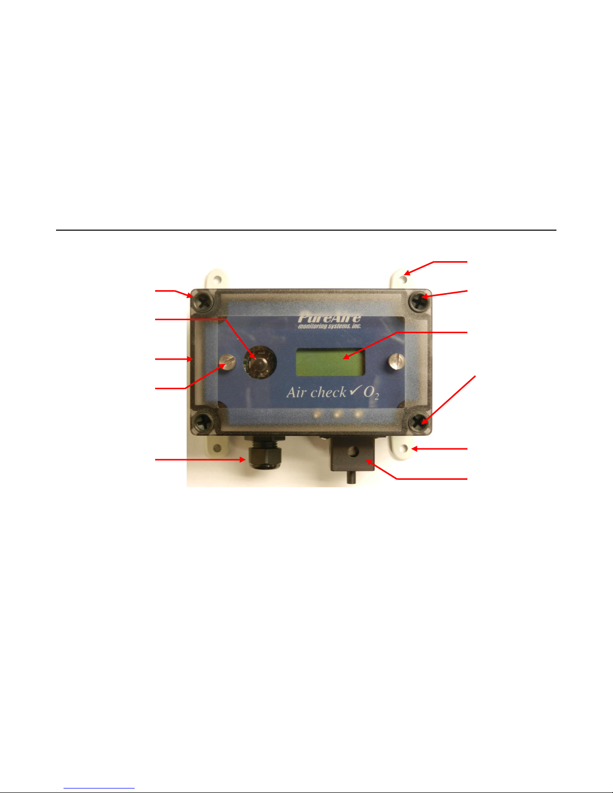
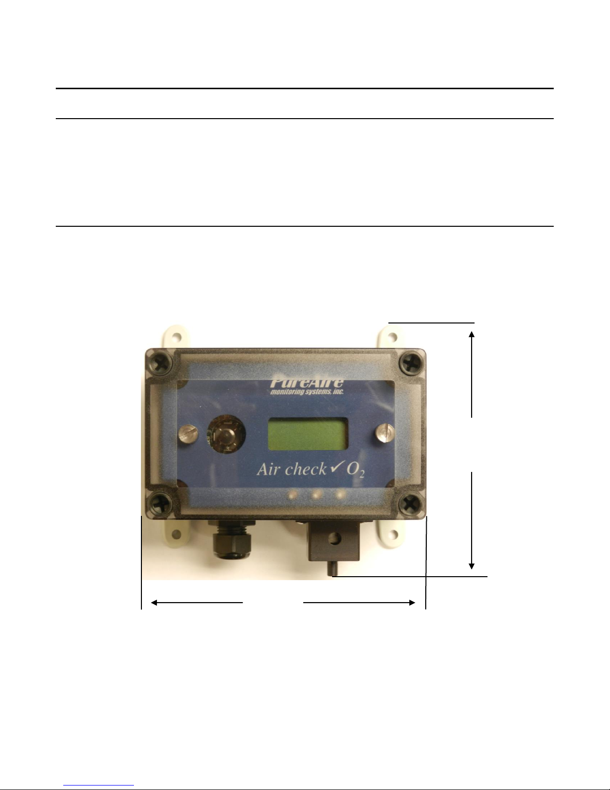
1.2 Component Identification
1.2.1 Front View Exterior
1. Digital Display — 3-digit backlit LCD digital display for showing the
oxygen levels in percent.
2. Joystick — Used for selecting and adjusting the built-in menus. The Air
Check O2 monitor is available with optional dual level user selectable
relays. The joystick is also used to select alarm levels, relay settings and
resetting any latching visual and audio alarms.
3. Cable Port — This is the opening in the transmitter housing for connecting
the 4-20 mA output and 24 VDC power cable.
4. Sensor Protector—The O
the cell as well as provides airflow to the cell. It also has a ¼ “ diameter tube
fitting to permit connecting a nitrogen cylinder for testing the O2 cell
response. NOTE: The sensor protector will feel HOT to the touch. This
is normal.
5. Oxygen Sensor — A zirconium oxide sensor, which detects and measures
the level of oxygen. When exposed to oxygen, the sensor outputs an
electrical signal proportional to the actual concentration of oxygen.
sensor is heated and the sensor protector shields
2
PureAire Monitoring Systems, Inc.
4
6
2
9
6
3
1
9
10
Al 2
Al 1
Fault
4 & 5
11
6. Mounting Feet — There are 4 feet used to mount the oxygen monitor to a
wall or other flat surface.
7. Transmitter Cover — A removable cover that protects the interior of the
transmitter.
8. Transmitter Cover Fasteners — There are 4 captive screws secure the
transmitter cover in place.
9. Electronics Fasteners — These captive screws secure the electronics to the
enclosure
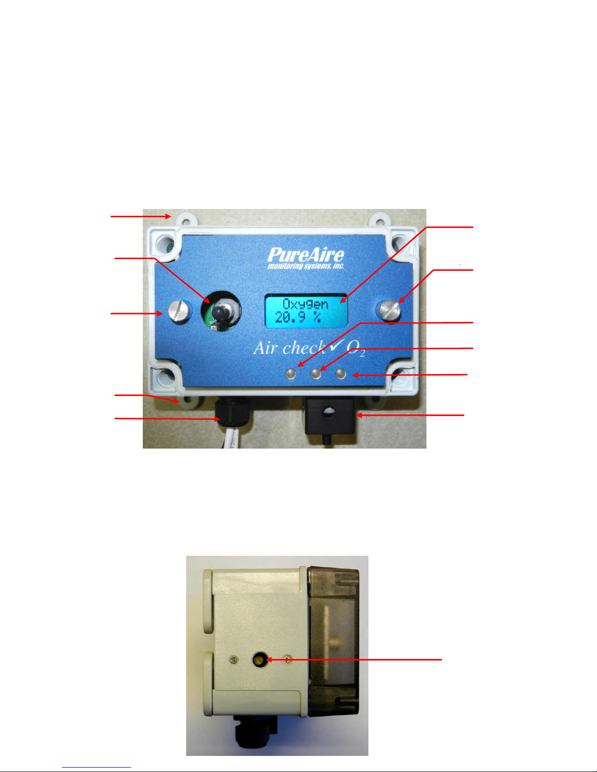
1.2.2 Front View Exterior with Relay Option
10. Alarm Indicators — 3 multi colored LED indicators for showing:
Alarm level 1 Orange LED
Alarm level 2 Red LED
Fault Alarm Yellow LED
1.2.3 Side View Exterior with Audio Alarm
PureAire Monitoring Systems, Inc.
5
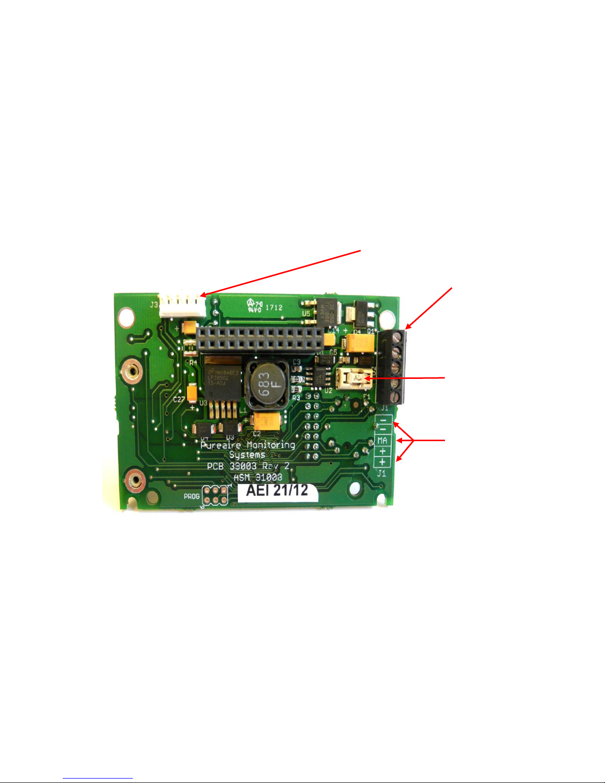
1. Power
Analog output
Terminal Block
Fuse
(Field
replaceable)
Common
Common
mA output
+ 24 VDC
+ 24 VDC
2. Sensor cell
connector
11. Audio Horn — This optional built-in horn is a 90dB high pitched audio
sound that will activate when the oxygen levels go below the selected alarm
thresholds. The audio alarm is non-latching and will automatically turn off
when the oxygen levels go above the alarm thresholds
NOTE: The audio alarm is an immediate alarm. Oxygen levels must recover
above the alarm thresholds before the horn turns off. There is no
alarm delay function available.
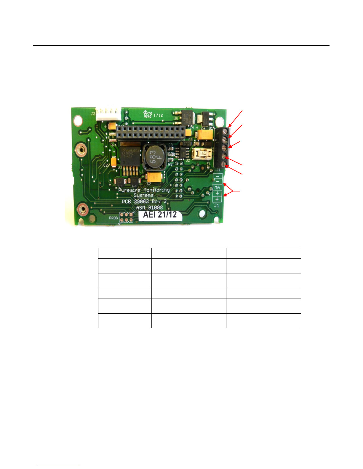
1.2.5 Transmitter Interior
1. Power Analog Terminal Block — This terminal block is where the 24VDC
power and 4-20 mA analog output connection is made.
NOTE: PureAire has added additional contacts for +24VDC power and Common to
accommodate additional wiring for remote horns and strobes
2. Sensor Cell Connector — This connector is where the Oxygen sensor cell
is connected. NOTE: Never connect the oxygen sensor to this connector
while the monitor is powered. This will damage the oxygen sensor
PureAire Monitoring Systems, Inc.
6
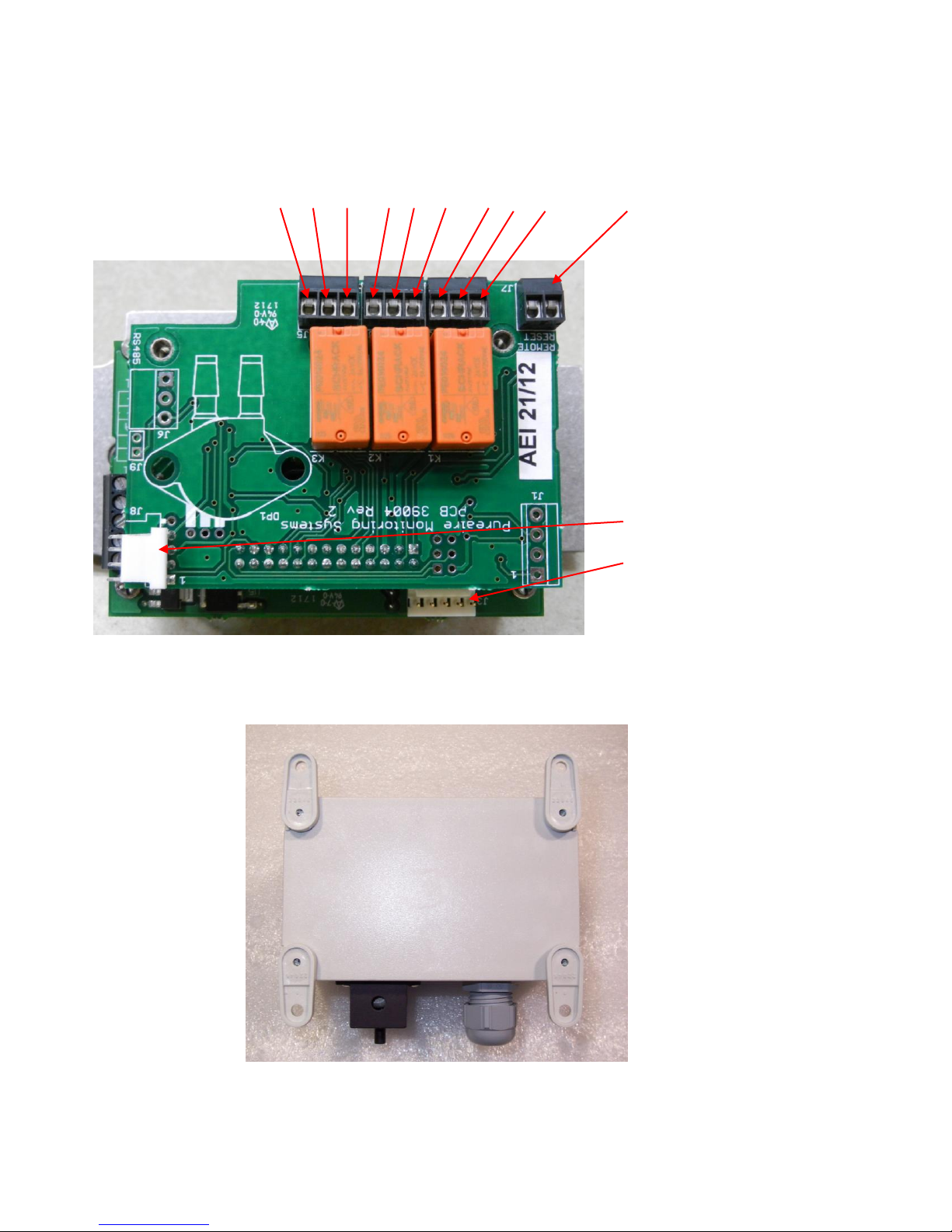
Relay 2 Relay 1 Fault Relay Remote
NC C NO NC C NO NC C NO Reset
Horn Connector
Oxygen sensor
connector
Mounting Feet
Can be oriented
in any direction
Feet can also be
removed for
mounting the O2
monitor flush
with a wall or
other surface
1.2.7 Alarm Relay Board
1.2.8 Enclosure Mounting Feet

PureAire Monitoring Systems, Inc.
7
2: Specifications
NOTE: For our continual product improvement, all specifications are subject to change without notice.
2.1 Performance Specifications
Sensor Type: Long Life Zirconium Oxide Sensor Cell 0-30%
Response Time: Within 1 second of any change in O2.
Accuracy: ± 1% of full scale
Fault Indicators: Loss of VDC power (analog signal drops to 0 mA).
Sensor cell failure: Fault relay activated. (Must have Alarm relay option for
cell failure to operate)
Operating Temp: -40° to 134°F (-40° to +55°C); consult PureAire for lower or higher operating
temperatures.
Humidity: 0 to 95% RH; consult PureAire for sensors which can operate in 100%
condensing RH environments.
Environment: Altitude 2000 m, PSU only UL spec. Pollution Degree 3, Intended for Indoor Use.
UL / CUL listing: Measuring Equipment E363306
Ce EN 61000-3-2:2006 EMC, EN 61000-3-3:2008 EMC, EN61010-1-3-2013 LVD
2.2 Gas Detection System
Type: Long Life Zirconium Oxide Sensor Cell, Range 0-30%
Sensor Life: 8 to 10+ years under normal conditions.
Transmitter: Microprocessor electronics with built-in 3-digit backlit LCD display
Joystick operated menus
2.3 Signal Outputs
Local Display: Digital display calibrated for Oxygen. The range is stated on the serial number
and can be accessed via the joystick on the front panel. In the measurement
mode pushing the joystick down will scroll the gas and range on the display.
Push the joystick down again to stop the scrolling and display the gas again.
Standard Analog Output: DC 4-20 mA
Optional Relay Output: Dual level user selectable alarm relays and one fault relay
Rated, 2amps @ 24VAC or 24VDC
2.4 Electrical Requirements
Power: 24 VDC external power. A regulated 24VDC power supply is required.
Consumption: Approximately 250mA
2.5 Physical Characteristics
Dimensions: 5.125 (W) x 3.15 (H) x 3.00 (D) inches; 130 x 80 x 76 mm (Max with feet)
Weight: 1.1 pounds (0.5 kg)
Enclosure Type: General purpose; not intended for explosive atmospheres.

PureAire Monitoring Systems, Inc.
8
Menu Function
Factory Default
Menu Defined
Set 4-20mA loop
The mA output is set at
the factory using a
calibrated Fluke meter.
Use this function to adjust the
Oxygen monitors 4mA, (Zero) and
20mA, (Span) to your PLC or
distributive control system.
Set Formats
LED and alarm relay
State **
Alarm 1 = Normal
Alarm 2 = Normal
Fault = Normal
Do you want the relays to
energize, (normal) or de-energize,
(fail safe) when the alarm
activates?
Set Alarm Threshold
Polarity
Alarm 1 = Inverted
Alarm 2 = Inverted
Audio = Inverted*
Do you want to alarm at a level
higher, (normal) or lower,
(inverted) than the alarm
threshold?
Set Latching
Alarm 1 = Non-latching
Alarm 2 = Non-latching
Audio = Non-latching
Do you want the alarm to
automatically reset? (non-latching)
or do you want to manually reset
the alarm? (latching)
Alarm Delay
Alarm = 5 seconds
How long do you want to wait
until the alarms activate?
Zero Suppression
000 = 0.00%
Refer to section 4.5.6
This function is Not Enabled on
the Oxygen monitor.
Set Alarm
Thresholds
Alarm 1 = 19.5 %
Alarm 2 = 18.0 %
Audio = 19.5%*
At what level do you want to
alarm?
Set Alarm Hysteresis
Alarm 1 = 0.0 %
Alarm 2 = 0.0 %
Audio = 0.0 %
For use when using the O2 monitor
for control of valves and process.
See Section 5.5.9
Sensor Adjustment
No factory default
For use when dynamically gas
calibrating the Oxygen monitor to
a known span gas.
See Section 6.2
Manage Passwords
Factory default is 557
For use when changing the
password from factory default to a
new password of your choice.
2.6 AirCheck O2 System Default Factory settings
The Air Check O2 Deficiency Monitor, when supplied with the optional Relay module, is shipped
with factory defaults for the alarm relay settings. The following are the factory defaults:
NOTE: The built in relay settings may be changed by the user in the field. Refer to
Section 5.5.2
* NOTE: The Audio alarm feature is optional.
** NOTE: The LED indicators on the front panel are connected directly to the alarm
relays.
PureAire Monitoring Systems, Inc.
9
5.50”
5.125”
3: Installation
3.1 Site Requirements
The Air Check O2 monitor enclosure should be mounted in an area free of vibration and electrical
noise or interference. If possible, avoid areas with high temperatures or condensing humidity.
WARNING: The Air Check
hazardous areas. Consult PureAire for information on enclosures for use in
hazardous environments.
O2 monitor is not designed for installation in
3.2 Mounting
3.2.1 Transmitter Enclosure
The Air Check O2 monitor is designed primarily for wall mounting and should be installed at a
height convenient for operation, maintenance, and viewing of the instrument display. The following is
a drawing of the mounting dimensions.
3.2.2 Air Check O
The transmitter and sensor should be installed in a location where gas leaks are likely to occur or
where released gases may accumulate. It should be mounted no closer than 12 inches above floor level.
Airflow within the monitored area, the characteristics of the gas (lighter or heavier than air), and the
position of workstations and personnel should all be considered in determining the most suitable
installation location.
monitor
2
PureAire Monitoring Systems, Inc.
10
Pin #
Connection
Description
-
Common (Signal Ground)
0V
-
Common (Signal Ground)
0V
MA
Signal Out
DC 4-20mA Output
+
Power
DC + 24V Input
+
Power
DC + 24V Input
- Common
- Common
mA* 4-20mA signal
output to PLC
+ 24VDC Power
+ 24VDC Power
Identification Legend
3.3 Wiring
The Air Check O2 monitor requires a single, 3-wire shielded cable for analog output
and 24 VDC power input. A three-wire shielded cable; 3-conductor, 18 AWG stranded
General Cable E2203S.30.860, or equivalent is recommended for the connection. The
analog out and VDC power in connections are made on the terminal block inside the
transmitter housing.
These connections are made as follows:
NOTE: PureAire has added additional contacts for +24VDC power and Common to
accommodate additional wiring for remote horns and strobes
* Caution: DO NOT connect to a powered current loop receiver. The Air Check
Oxygen monitor supplies the current loop power.

PureAire Monitoring Systems, Inc.
11
Oxygen
239 WARM
3.4 Initial Startup
Once installation of the gas detector has been completed, it is ready for startup. The following
procedures should be performed before putting the instrument into operation:
1. Check the integrity of all wiring.
2. Apply 24 VDC power.
The instrument should now be powered up. Upon power up, the Air Check O2 monitor LCD
displays the PureAire logo and then starts a 4-minute, (240 second) count down as the current to the
zirconium oxide O2 sensor stabilizes. The monitor will output a 4 mA signal during the entire warmup period. After the countdown, the oxygen sensor will continue to reach its operating temperature for
approximately 30 minutes and the reading displayed will slowly increase to ambient. Do not make
any adjustments to the reading until after the monitor has been powered for at least an hour.
NOTE: When the Air Check O
momentarily at the completion of the warm up.
NOTE: The Air Check O
2
See section 6.1 for instructions on adjusting.
monitor is supplied with an Audio Horn, it will activate
2
monitor’s reading may be adjusted to the ambient oxygen level.

PureAire Monitoring Systems, Inc.
12
Condition
Analog Signal
**Supply Voltage Out of
Range Fault code 16
Analog output drops to 2 mA
Transmitter cable cut
Analog output drops to 0 mA
O2 Cell complete failure
Fault Code 128
Analog output drops to 2 mA
Fault Relay activates
(Available with Relay Option Only)
O2 System Warm Up
Analog output drops to 2 mA
Fault Relay activates and turns off when system
is in the Oxygen operation mode
(Available with Relay Option Only)
O2 Cell voltage fault
Fault Code 64
Analog output drops to 2 mA
Fault Relay activates
(Available with Relay Option Only)
EEPROM Fault 08
Analog output drops to 2mA
NOTE: All system faults are displayed on the front panel. Each fault
has it’own specific code to identify the specific problem. Please
contact PureAire whenever a fault is displayed.
** When using your own power supply please insure that the voltage
is regulated to 24VDC +/- 0.5 volts. If the voltage is too low or high
you will activate a “Supply Voltage Out of Range fault and disable
the monitor.
4: Normal Operation
The Air Check O2 monitor is a single point monitor designed for the continuous detection and
measurement of ambient oxygen concentration levels.
4.1 Signal Outputs
The Air Check O2 monitor outputs a continuous 4-20 mA analog signal proportional to the
measured concentration of oxygen. 4 mA represents 0% O2 and 20 mA represents 30% O2 which is the
full range. In the event of a system fault, a specific factory defined code will be displayed on the local
digital display. This code will indicate the exact nature of the system fault.
CAUTION: DO NOT connect to a powered current loop receiver. The Air Check
Oxygen monitor supplies the current loop power.
4.2 Instrument Faults
The Air Check O2 monitor incorporates a number of self-checking features to
ensure reliable operation. In the event that a fault condition is detected, the
analog output signal is altered: A few common error codes are displayed in the
following table:
NOTE: If a Fault condition clears itself, (Yellow LED is no longer illuminated)
The Fault message will continue to scroll until manually cleared.
To clear the fault message, push the joystick down (- Minus)

PureAire Monitoring Systems, Inc.
13
Items to check
Check for power and proper operation
Condition / status when
operating properly
Unit should be outputting a 17.4 mA signal when
the oxygen level is at 20.9%. The LCD digital
display should also indicate 20.9% 02 when the
oxygen is at ambient levels.
4.3 Routine Maintenance Schedule
Continuous gas detection systems depended upon to measure and detect hazardous gas leaks in the
workplace requires periodic maintenance to ensure proper operation. The frequency with which this
routine maintenance is required depends on the environment. The following table is intended to serve
as a general guideline for routine maintenance. The conditions in your particular application, as well as
your organization’s maintenance policies, will ultimately determine the best routine maintenance
schedule for your equipment. Routine Visual Checks
4.3.2 Recommended Routine Maintenance Schedule
Routine Visual Checks Every 6 - 12 months
Sensor Verification with nitrogen Every 6 - 12 months**
** The ambient oxygen level is 20.9%; therefore, under ambient conditions verification of the Air
Check O2 monitor to 20.9% oxygen is constantly being performed. The O2 monitor only requires
periodic testing with nitrogen to verify the cells response to low oxygen levels. See Section 5.5.10 for
how to make minor adjustments.
4.4 Loss of Power Indicator
In the event the Air Check O2 monitor loses 24VDC power, the 4-20 mA analog output signal drops
to 0mA. The LCD display will also display a blank screen.
4.5 Alarm Reset
It the Air Check O2 monitor is supplied with the optional alarm relays, whenever the monitors alarms
are activated, the built-in alarm relays, panel mounted LED’s and optional audio horn will also
activate. When the relay settings are non-latching, the alarm relays, LED’s and horn will automatically
reset. If the relay settings are latching, then a manual reset of the alarms are required. Resetting the
alarms can be performed through use of the joystick or through the use of the remote reset function.
Joystick – You must enter the password to enter the reset function. After the password is entered and
accepted, push the joystick in; (enter) to reset the alarms.
Remote Reset – See section1.2.7. The alarm relay board has a two-pin connector for wiring to a
remote switch. When connected to a switch, this remote reset will bypass the joystick and a password
will not be needed to reset the alarms.
NOTE: The oxygen levels must recover above the alarm thresholds before the horn can be
reset from the remote reset switch or joystick.
 Loading...