

Purdy AND-TFT-5VX-4HB-KIT User Manual
Displays
AND-TFT-5VX-4HB-KIT
640 x 480 Pixels
LCD Color Monitor
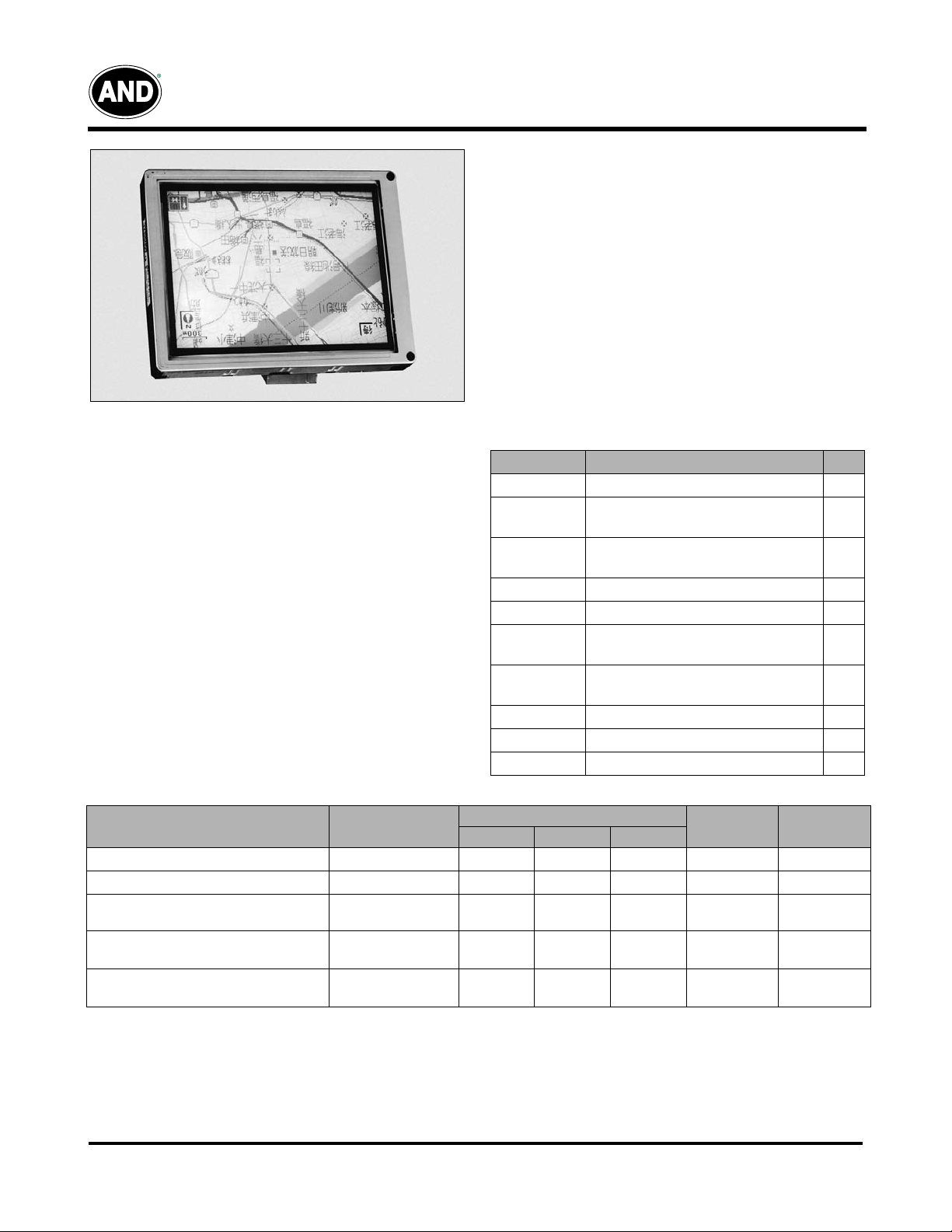
The AND-TFT-5VX-KIT is a compact full color TFT LCD
module, whose driving board is capable of converting
composite video signals to the proper interface of LCD panel
and is suitable for computer peripheral, industrial meter,
image communication and multi media.
This device consists of an amorphous silicon panel with
back-light, incorporating a TFT-array that has 640 x 480
pixels on a 5 inch diagonal screen, with pixel in stripe
configuration, 262,144 display colors and a TTL transmission
interface.
Features
• VGA (640 x 480 pixels) resolution
• Amorphous silicon TFT LCD panel with back-lit unit
• Pixel in stripe configuration
• Light weight and slim
• Displays 262,144 colors
• Optimum Viewing Direction: 6 o’clock
•
Portrait mode
• TTL transmission interface
•
RoHS compliant
Product specifications contained herein may be changed
without prior notice. It is therefore advisable to contact Purdy
Electronics before proceeding with the design of equipment
incorporating this product.
Mechanical Characteristics
Parameter Specification Unit
Screen Size 5.0 (diagonal) inch
Display
Format
Display
Colors
Active Area 74.88 (H)x101.76(V) mm
Pixel Pitch 0.156(H)x0.159(V) mm
Pixel
Configuration
Outline
Dimension
Weight 120±10 g
Back-light CCFL, 1 tube
Diplay Mode Normally white
640 (H) x (R, G, B) x 480(V) dot
262,144
Stripe
91.4(H)x119.3(V)x7.9(D) mm
Recommended Driving Condition for Back Light Ta=25ºC
Parameter
Lamp Voltage
Lamp Current
Lamp Frequency
Symbol
V
L
I
L
P
L
Specifications
Min. Typ. Max.
390 410 430 V
4.0 6.0 8.0 mA Note 1
30 45 60
Unit Remark
I
L
KHZ
Note 2
=6mA
Starting Voltage (25ºC)
(Reference Value)
Starting Voltage (0ºC)
(Reference Value)
Note 1 : In order to satisfy the quality of B/L, no matter what inverter is used, the output lamp current must be between
Min. and Max. to avoid the abnormal display image caused by B/L.
Note 2 : The waveform of lamp driving voltage should be as close to a perfect sine wave as possible.
Note 3 : The “Max of starting voltage” means the minimum voltage of inverter turns on the CCFL and it should be applied to
the lamp for more than 1 second to start up. Otherwise the lamp may not be turned on.
05/13/03
Tel: 408.523.8200 • Fax: 408.733.1287 • sales@purdyelectronics.com • www.purdyelectronics.com
Purdy Electronics Corporation • 720 Palomar Avenue • Sunnyvale, CA 94085
Vs
Vs
– – 640 Vrms Note 3
– – 740 Vrms Note 3
1
2
Displays
AND-TFT-5VX-4HB-KIT
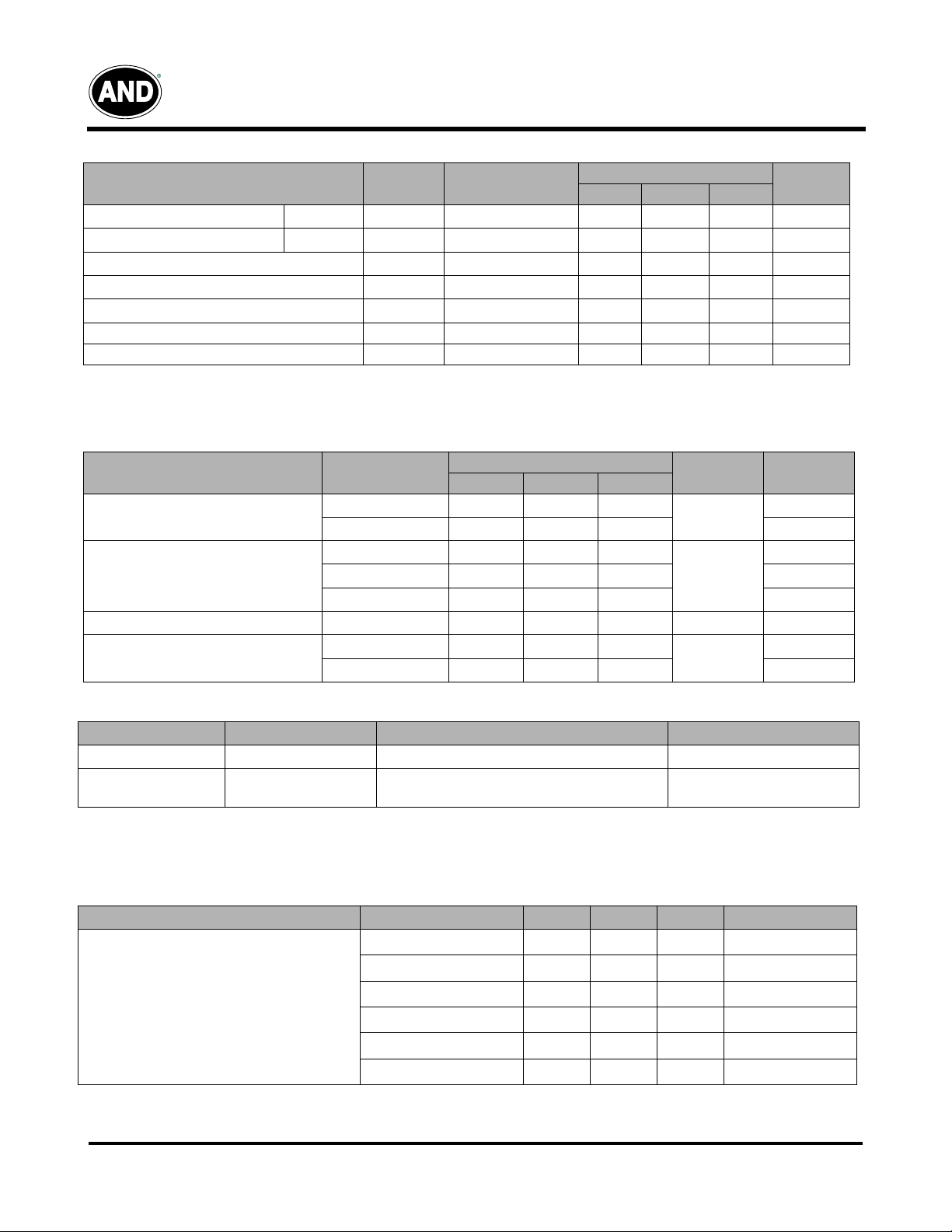
Power Consumption
Parameter Symbol Conditions
Supply Current for Gate Driver
Supply Current for Gate Driver
Hi level
Low level
Supply Current for Source Driver(Digital)
Supply Current for Source Driver (Analog)
Supply Current for Gate Driver (Digital)
I
I
I
DD1
I
DD2
I
GG
EE
CC
V
V
V
V
GG
V
EE
DD1
DD2
CC
= +19V
= -10V
= +3.3V
= +9.5V
=+3.3V
Specifications
Typ. Max. Unit
0.162 0.202 mA
0.22 0.27 mA
11.26 14.07 mA
16.2 22.5 mA
0.0153 0.0192 mA
Remark
LCD Panel Power Consumption - 196.31 266.75 mW Note 1
Back Light Lamp Power Consumption - 2.46 - W Note 2
Note 1: The power consumption for backlight is not included
Note 2: Backlight lamp power consumption is calculated by I
L
x V
.
L
Recommended Operating Conditions Vss1=Vss2=GND=OV, Ta = 25°C
Item
Supply Voltage for Source Driver
Supply Voltage for Gate Driver
V
Voltage V
oom
Digital Input Voltage
Symbol
V
DD1
V
DD2
V
GG
V
EE
V
CC
ccm
V
IH
V
IL
0.7 V
Specifications
Min. Typ. Max.
2.3 3.3 3.6
6.5 9.5 13.5
V
7.0 -
EE
+40.0
-20.0 - -5.0
2.3 3.3 5.5
- 3.6 - V
CC
-
0-
V
0.3 V
CC
CC
Unit Remark
V
V
V
Backlight Driving
Pin No Symbol Description Remark
1 VL1 Input terminal (Hi voltage side) Wire color : Pink
2 VL2 Input Terminal (Low voltage side)
Note 1: Low voltage side of backlight inverter connects with ground of inverter circuits.
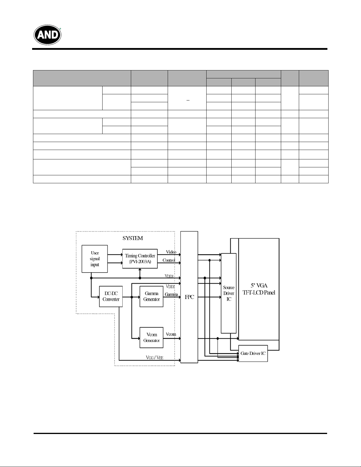
Absolute Maximum Ratings: V
Parameters
Supply Voltage
05/13/03
Tel: 408.523.8200 • Fax: 408.733.1287 • sales@purdyelectronics.com • www.purdyelectronics.com
Purdy Electronics Corporation • 720 Palomar Avenue • Sunnyvale, CA 94085
=V
ss1
=GND=OV, Ta=25ºC
ss2
Symbol Min. Max. Unit Remark
V
DD1
V
CC
V
DD2
V
GG
V
-V
GG
EE
V
EE
-0.5 5.0 V
-0.3 6.0 V
-0.5 12.0 V
-0.3 40.0 V
-0.3 40.0 V
-20 0.3 V
Wire color : White
Note 1
Displays
Optical Characteristics
Parameter
Horizontal
Viewing Angle
Contrast Ratio CR 200 400 – – Note 2
Response Time
Brightness L
Luminance Uniformity U 70 75 – % Note 4
Lamp Life Time 50000 – –
White Chromaticity
Cross Talk
Vertical
Rise Tr
Fall Tf – 25 50
Symbol Conditions
θ
= 21, 22
10
θ
= 12 30 35 –
θ
= 11 45 50 –
x 0.28 0.31 0.34
y 0.34 0.37 0.40
CR >
θ
= 0º
θ
=
0º/
ψ
= 0
θ
=0º – – 3.5 % Note 5
Min. Typ. Max.
±55 ±60
–1530
– 1,000 – cd/m2
AND-TFT-5VX-4HB-KIT
Specifications
Unit Remarks
deg
ms Note 3
hr
–
Note 1
At 6mA
Block Diagram
05/13/03
Tel: 408.523.8200 • Fax:408.733.1287 • sales@purdyelectronics.com • www.purdyelectronics.com
Purdy Electronics Corporation • 720 Palomar Avenue • Sunnyvale, CA 94085
3

Displays
AND-TFT-5VX-4HB-KIT
Recommended Operating Conditions (Driving for Backlight) Ta = 25°C
Item
Lamp Voltage
Lamp Current
Lamp Frequency
Kick-Off Voltage (25 °C)
Kick-Off Voltage (0 °C)
Note 1: The wave form of lamp driving voltage should be as close to a perfect SIN wave as possible
Note 2: This value is not output voltage of inverter. The voltage of inverter must be larger than the starting voltage.
Symbol Remark
I
V
L
I
L
P
L
V
S
V
S
= 5 mA
L
– 4.5 5.0 5.5 mA
Note 1 40 43 80 KHz
Note 2
Specifications
Min. Typ. Max.
Unit
432 480 528 Vrms
– – 600 Vrms
– – 800 Vrms
Input / Output Terminals:
TFT-LCD Panel Driving
CN 1
Pin #. Symbol I/O Function Remark
1 DIO1 I/O Horizontal Start Pulse Signal Input or Output Note 1
2 VSS1 I Ground
3 VDD1 I Power Supply for Source
4
5
6
7
8
9 R2 I Red Data
10
11
12 R5 I Red Data (MSB)
13 Vss1 I Ground
14 G0 I Green Data (LSB)
15 G1 I Green Data
16 G2 I Green Data
17 G3 I Green Data
18 G4 I Green Data
19 G5 I Green Data (MSB)
20 VSS1 I Ground
21 B0 I Blue Data (LSB)
22 B1 I Blue Data
23 B2 I Blue Data
24 B3 I Blue Data
25 B4 I Blue Data
26 B5 I Blue Data (MSB)
27 LD I Load output signal Note 3
28 REV I Data invert control Note 4
29 POL I Polarity Note 5
30 DIO2 I/O Horizontal Start Pulse Signal Input or Output Note 6
CLK
VSS1
R/L
R0
R1
R3
R4
I Horizontal Shift Clock)
I Ground
I Up/Down selection Note 2
Red Data (LSB)
I
I Red Data
I Red Data
I Red Data
05/13/03
Tel: 408.523.8200 • Fax:408.733.1287 • sales@purdyelectronics.com • www.purdyelectronics.com
Purdy Electronics Corporation • 720 Palomar Avenue • Sunnyvale, CA 94085
4
 Loading...