


PRELIMINARY
AND-TFT-35XS-LED-KIT
3.5" TFT LCD
LCD Color Monitor
The AND-TFT-35XS-LED-KIT is a compact full color TFT
LCD module, that is suitable for camcorder, digital camera
applications and other electronic products which require high
quality flat panel displays. This device consists of a twisted
nematic (TN) liquid crystal cell, that incorporates a TFT-array
that has 320 x 234 pixels on a 3.5 inch diagonal screen, X
and Y drivers, an LSI controller, and a built-in CCFL
backlight.
Features
• Long life LED backlight
• No controller chip is necessary
• Compatible with NTSC or PAL system (switchable)
• High Resolution: 112,320 dots
• Optimum viewing direction: 6 o’clock
• Up/Down and Left/Right image inversion
• RoHS compliant
Mechanical Characteristics
Item
Specification Unit
Screen Size 3.5 inch diagonal inch
Outline
Dimensions
83.5 (W) x 63.1 (H) x 3.6 (D) mm
Active Area 71.6 (W) x 52.65 (H) mm
Surface
Treatment
Pixel Number
(RGB trio)
Pixel
Configuration
Anti-Glare –
320 (W) x 234 (H) –
Delta –
Dot Pitch 0.0.74 (W) x 0.225 (H) mm
Weight 58 ± 5 g
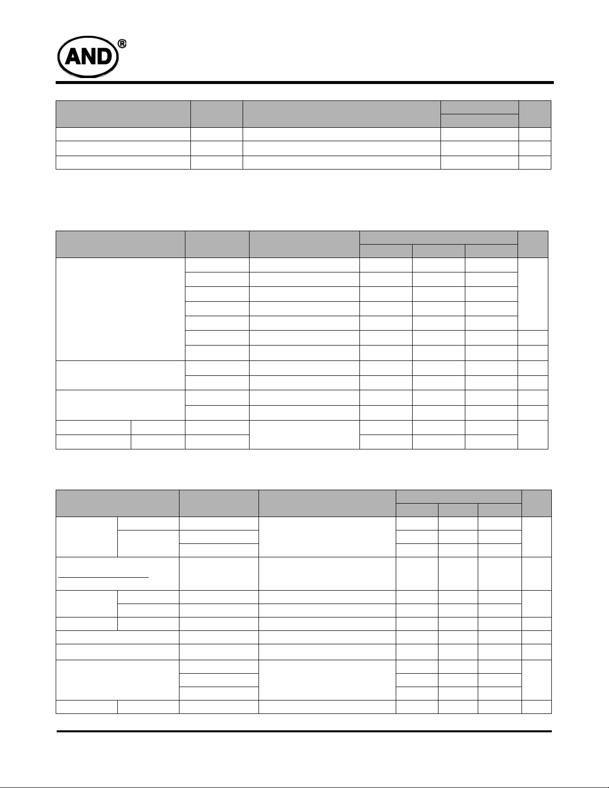
Absolute Maximum Rating
Absolute Maximum Rating
Min. Max.
-0.3 +7.0
-0.3 +7.0
-0.3 +45
-.23 +0.3
+15 +40
-0.3 +7.3 V
for Source
Driver
Supply
Voltage
for Gate
Driver
Analog Input Voltage
, V
( means V
V
R
G,
B
Item
Analog
Digital
Positive
Negative
)
Symbol Conditions
AV
DD
V
DD
V
V
V
GH -
V
VIDEO
GH
GL
V
GL
Ta = 25°C
Operating Temperature
(define that contrast, response time, other display optical
Top – 0 +60 °C
characters are Ta=+25)
Storage Temperature Tstg – -20 +70 °C
NOTES: GND = 0V, Ta = 25ºC
Unit
V
Product specifications contained herein may be changed without prior notice.
It is therefore advisable to contact Purdy Electronics before proceeding with the design of equipment incorporating this product.
1/15/09
Tel: 408.523.8200 • Fax: 408.733.1287 • sales@purdyelectronics.com • www.purdyelectronics.com
Purdy Electronics Corporation • 720 Palomar Avenue • Sunnyvale, CA 94085
1
T
AND-TFT-35XS-LED-KIT
Item
(Ta =
25°C)
Symbol Remarks
Specifications
Typ.
Units
Power Consumption
LCD Panel Power Consumption – Power consumption for backlight is not included 33.5 mW
x V
Backlight Lamp Power Consumption –
calculated by I
.
L
L
0.65 W
Total Power Consumption – – 0.69 W
Backlight Connector
JST BHR-03VS-1
Recommended Operating Conditions
Item
Power Supply
(Ta = 25°C)
Video Signal (V
V
COM
, V
V
)
R
G,
B
H Level V
L Level V
Note 1: STH1, STH2, CPH1, CPH2, CPH3, Q2H, INH, CPV, XOE,
DIO1, DIO2
Symbol Remarks
V
CC
V
DD
AV
DD
V
GH
V
EE
V
GL AC
V
GL DC
V
i AC
V
i DC
V
COM AC
V
COM DC
IH
IL
AC Component of V
DC Component of V
AC Component, Note 2 – +4.0 +4.2
DC Component – +2.5 – V
AC Component of V
DC Component of V
Min. Typ. Max.
+4.5 +5.0 +5.5
+3.0 +3.3 +3.6
+4.5 +5.0 +5.5
+14.5 +15.0 +15.5
-15.5 -15.0 -14.5
GL
GL
COMM
COMM
Note 1
Note 2: Both NTSC & PAL system Video Signal input waveform is
based on 8 steps gray scale.
– +6.0 –
-12.5 -11.0 -9..5 V
– +6.0 –
+0.9 +1.0 +1.1 V
+0.7 V
––
Specifications
DD
Unit
V
V
P-P
V
P-P
V
P-P
––
+0.3 V
DD
V
Optical Specifications
Viewing Angle
Item
Horizontal
Vertical
Symbol Conditions
θ
θ
(to 12 o’clock) 10 15 –
θ
(to 6 o’clock) 30 35 –
Contrast Ratio
Luminance when LCD is
Luminance when LCD is Black
Response Time
White
Rise Tr
Fall Tf
CR At optimized viewing angle 110 150 – –
Transmission Ratio
Uniformity U
Brightness LUM
X
White Chromaticity
Tc 6650 6850 7050
Lamp Life Time +25°C –
2
Tel: 408.523.8200 • Fax: 408.733.1287 • sales@purdyelectronics.com • www.purdyelectronics.com
Purdy Electronics Corporation • 720 Palomar Avenue • Sunnyvale, CA 94085
Specifications
Min. Typ. Max.
± 45 ± 50 –
≥
CR
10
θ
=0° – 15 30
φ
=0° – 25 50
– 7.5 8.0 8.5 %
–
–
65 70 – –
200 250 –
0.280 0.310 0.340
θ
=0°
decay to 75%
10,000 – – hr
Unit
deg
ms
cd/m
–Y 0.310 0.340 0.370
1/15/09
2
AND-TFT-35XS-LED-KIT
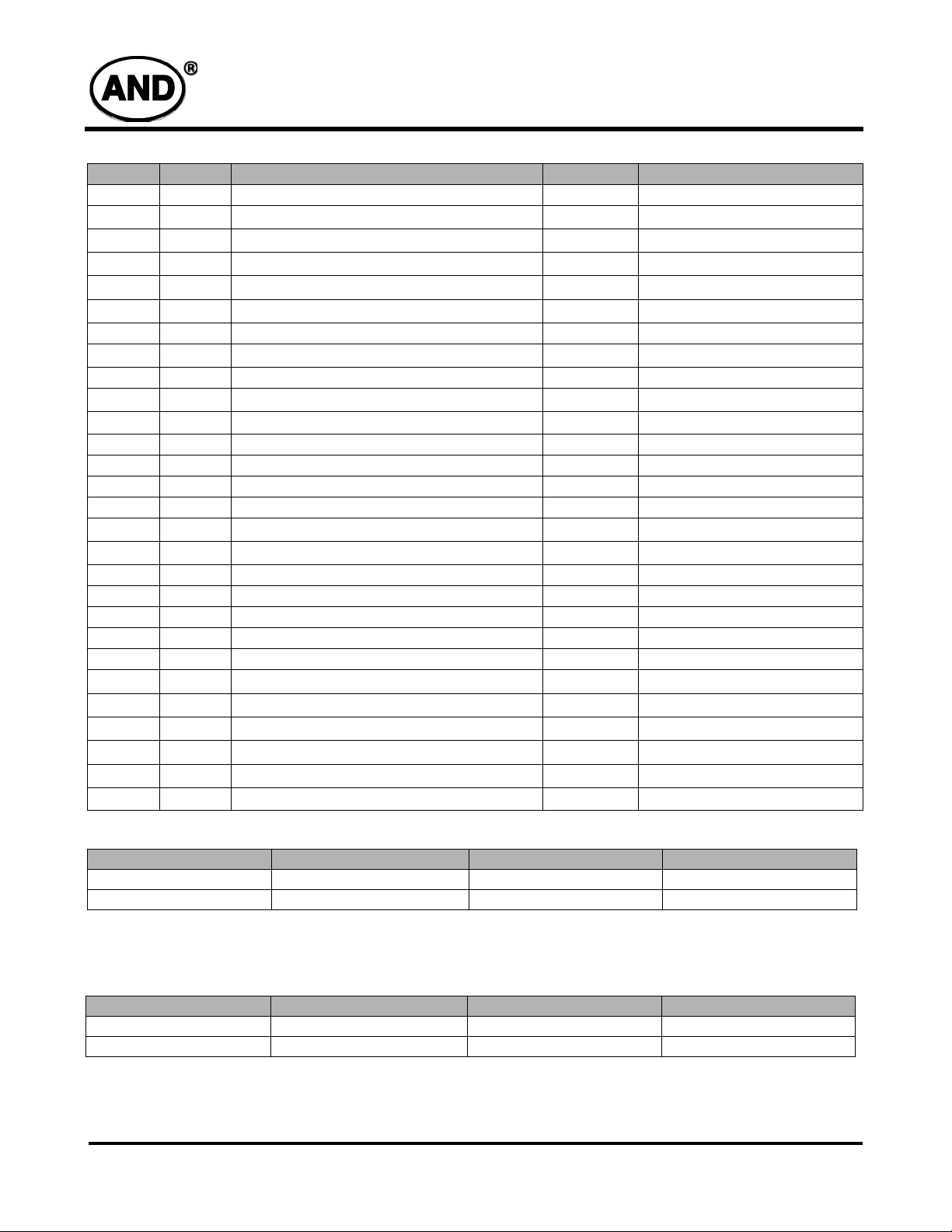
Interface Pin Assignment
Pin No.
1 STH1 Start pulse for source driver I/O Note 1
2
3
4
5
6
7 VSS Digital GND I
8
9 CPH1 Sampling and shift clock for source driver I
10
11
12 STH2 Start pulse for source driver I/O Note 1
13 Q2H Video input rotation control I
14 INH Output enable for source driver I
15 R/L Left/Right Control for source driver I
16
17
18 XOE Output enable for gate driver I
19 CPV Clock input for gate driver I
20 U/D Up/Down Control for gate driver I
21 DIO2 Vertical start pulse I/O Note 5
22 DIO1 Vertical start pulse I/O Note 5
23
24
25
26
27
28
Symbol Function Input/Output Remark
AV
AV
V
V
V
V
DD
CPH2
CPH3
V
COM
V
COM
V
GL
V
EE
V
SS
V
CC
V
GH
NC
Analog GND for source driver I –
SS
Analog power input for source driver I
DD
Video Input B I Note 4
B
Video Input G I Note 4
G
Video Input R I Note 4
R
Digital power input I Note 3
Sampling and shift clock for source driver I
Sampling and shift clock for source driver I
Common electrode voltage I Note 4
Common electrode voltage I Note 4
Gate off voltage (alternative every 1-H) I
Gate driver negative voltage I Note 6
GND I
Logic power for gate driver I
Gate on voltage I
No connection –
Note 2
Note 4
Note 3
Note 7
Note 1: STHL, STHR and R/L mode
R/L
High (VDD) Input Output Left to Right
Low (0 Volt.) Out put Input Right to Left
Note 2: AV
Note 3: V
Note 4: V
= +5V (Typ.)
DD
, V
DD
CC
= 6V
COM
= +5V (Typ.)
PP
Note 5: Dio1, DIO2 and U/D mode
U/D
High (VDD) Input Output Down to Up
Low (0 Volt.) Output Input Up to Down
Note 6: V
Note 7: V
1/15/09
= -15V (Typ.)
EE
= -15V (Typ.)
GH
Tel: 408.523.8200 • Fax:408.733.1287 • sales@purdyelectronics.com • www.purdyelectronics.com
Purdy Electronics Corporation • 720 Palomar Avenue • Sunnyvale, CA 94085
STHL STHR Remarks
DIO1 DIO2 Remarks
3
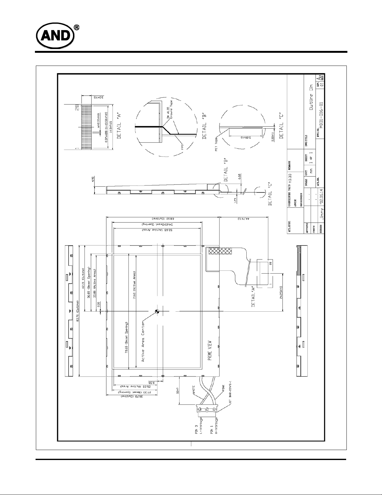
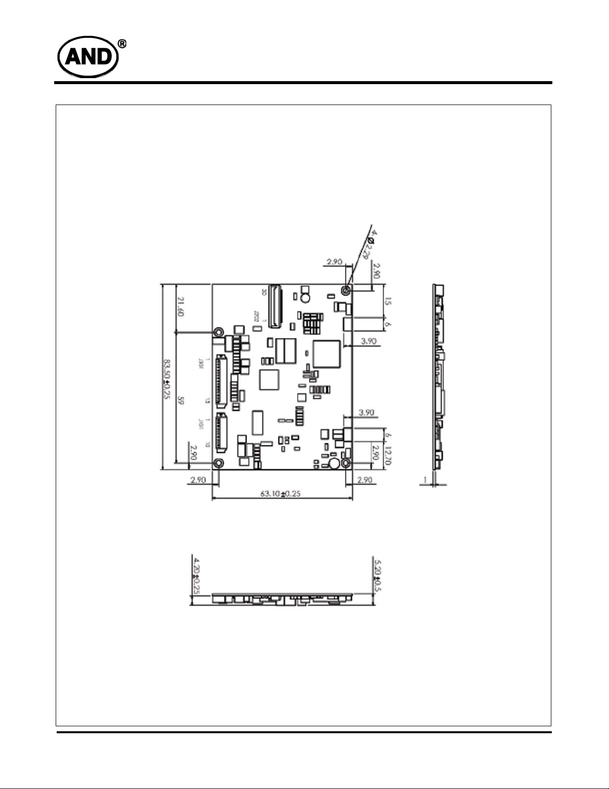
Dimensional Outline
AND-TFT-35XS-LED-KIT
4
Tel: 408.523.8200 • Fax:408.733.1287 • sales@purdyelectronics.com • www.purdyelectronics.com
Purdy Electronics Corporation • 720 Palomar Avenue • Sunnyvale, CA 94085
1/15/09
PC-TFT-35XS-LED
Interface Board
Features
• Used for TFT-LCD display: 3.5” AND-TFT-35XS-LED
• Ultra compact, light, thin and small
• DC/DC DC/AC Video Decoder all in one
• NTSC/PAL Video Input Switch
• Up/Down, Left/Right Display Reverse
• Composite Video RGB Mode Switchable
• RoHS Compliant
Mechanical Characteristics
Item Specification Unit
Outline Dimension 62.5 (W) x 52 (H) x 7.5 (D) mm
Weight 20 g
The PC-TFT-35XS-LED is designed to work with
the AND-TFT-35XS-LED color TFT display which
is suitable for security, video game, door phone,
video phone, portable TV and instrument display
applications.
Do not use for products which demand extremely
high performance in terms of functionality,
reliability, or accuracy. Products such as:
aerospace equipment, control equipment for
nuclear power industry or medical equipment
related to life support.
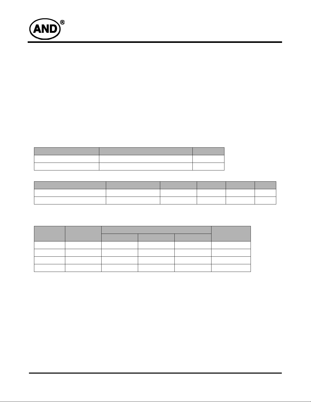
PC-TFT-35XS-LED
Absolute Maximum Rating
Item
Operating Temperature Top – 0 60 °C
Storage Temperature Tstg – -30 80 °C
DC to DC Converter
Voltage
(V)
+5V 50-100 4.8 5.0 5.1 50
+7.5V 6~10 7 9.1 9.5 200
+15V 5~5 12 15 16 200
-12V 2-5 -9 -12 -15 200
Input
Characteristics:
Typical Input Voltage : 8V DC
Input Voltage Range : 6VDC to 15 VDC
I nput Current: 150mA, Typical at 12VDC with panel load.
Inrush Current Max : 250mA at 6VDC, 130mA at 15VDC Cold start at
25C, 5.0VDC with panel load.
Current
(mA)
Symbol Conditions Min. Max. Unit
Total Regulation
Min. Typ. Max.
Ripple &
Noise (mV)
Sync. Pulse: 60KHz Typical
1/15/09
Tel: 408.523.8200 • Fax:408.733.1287 • sales@purdyelectronics.com • www.purdyelectronics.com
Purdy Electronics Corporation • 720 Palomar Avenue • Sunnyvale, CA 94085
5
PC-TFT-35XS-LED
T
Pin
No.
e
r
Connector:
Pin No: FC12D (Bottom Contact)
Pitch: FC 1.0mm
Symbol I/O Description Remarks
1 +5V O 5.0V output –
2 COL I color adj. –
3 BRT I brightness adj. –
4 CNT I contrast adj. –
5 Video I composite video signal The signal resistance is 75 Ω , 1V p-p.
6 U/P I up/down scan control +5V or GND
7 R/L I left/right scan control +5V or GND
8 GND I ground –
9 GND I ground –
10 +12V I +12V DC power input –
11 HSY O HSY output –
12 VSY O VSY output –
Output Characteristics:
DC to DC Backlight Inverter:
Starting Voltage : 15.8VDC, typical at 6.0 VDC
Working Voltage: 16.0 VDC, typical at 15 VDC
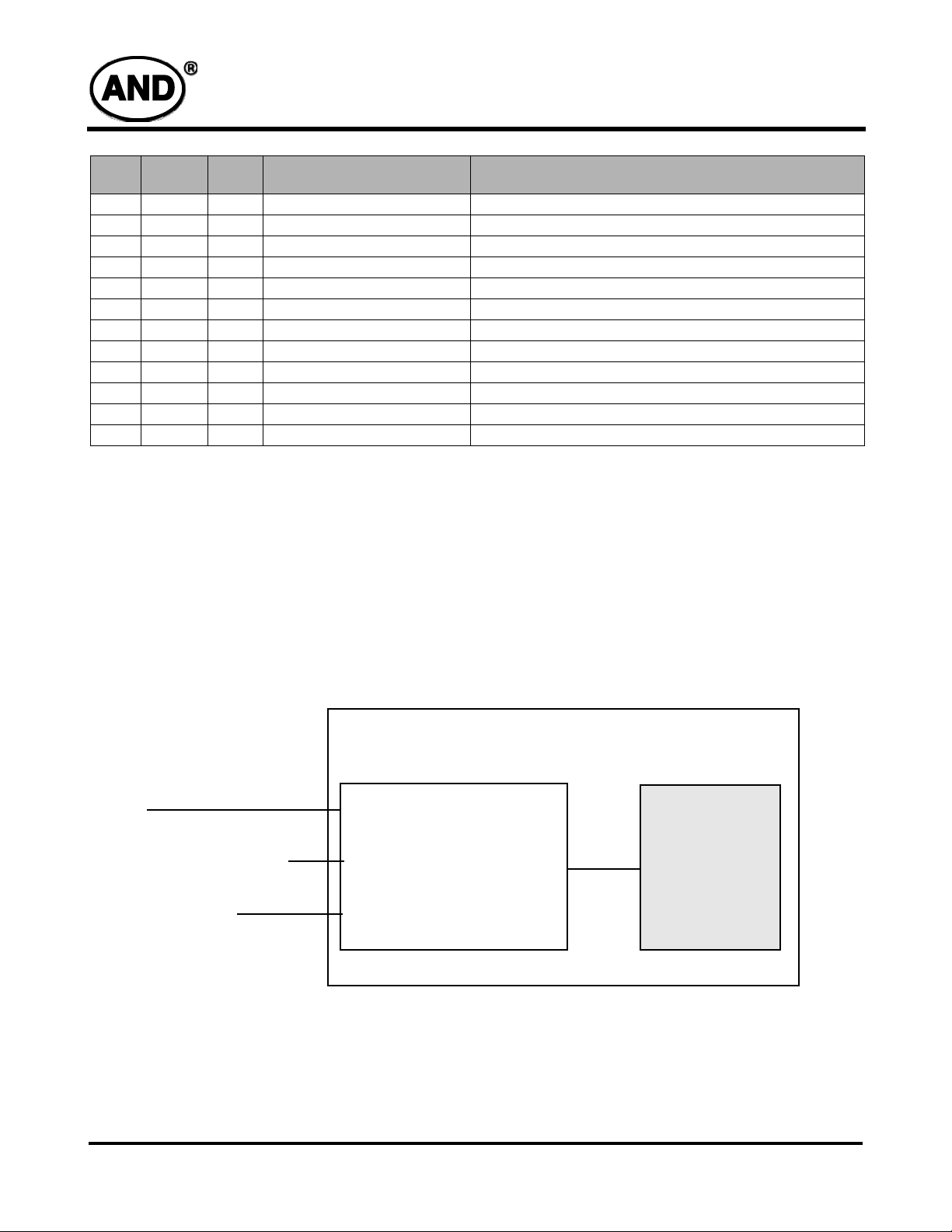
Block Diagram
Power
Composite Video/RGB Signal
Picture control signal
Working Current: DC 10mA ± 20% typical for general application.
AND-TFT-35XS-LED
AND-TFT-35XS-LED PC-TFT-35XS-LED
Video Chroma Signal
Processing
DC/DC – LED Driver
6
Tel: 408.523.8200 • Fax:408.733.1287 • sales@purdyelectronics.com • www.purdyelectronics.com
Purdy Electronics Corporation • 720 Palomar Avenue • Sunnyvale, CA 94085
1/15/09
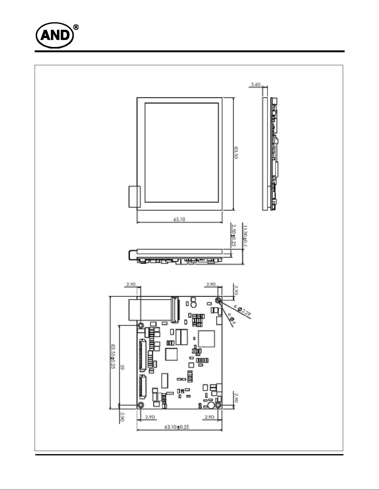
Dimensional Outline
PC-TFT-35XS-LED
1/15/09
Tel: 408.523.8200 • Fax:408.733.1287 • sales@purdyelectronics.com • www.purdyelectronics.com
Purdy Electronics Corporation • 720 Palomar Avenue • Sunnyvale, CA 94085
7
Dimensional Outline
PC-TFT-35XS-LED
8
Tel: 408.523.8200 • Fax:408.733.1287 • sales@purdyelectronics.com • www.purdyelectronics.com
Purdy Electronics Corporation • 720 Palomar Avenue • Sunnyvale, CA 94085
1/15/09
 Loading...