

Displays
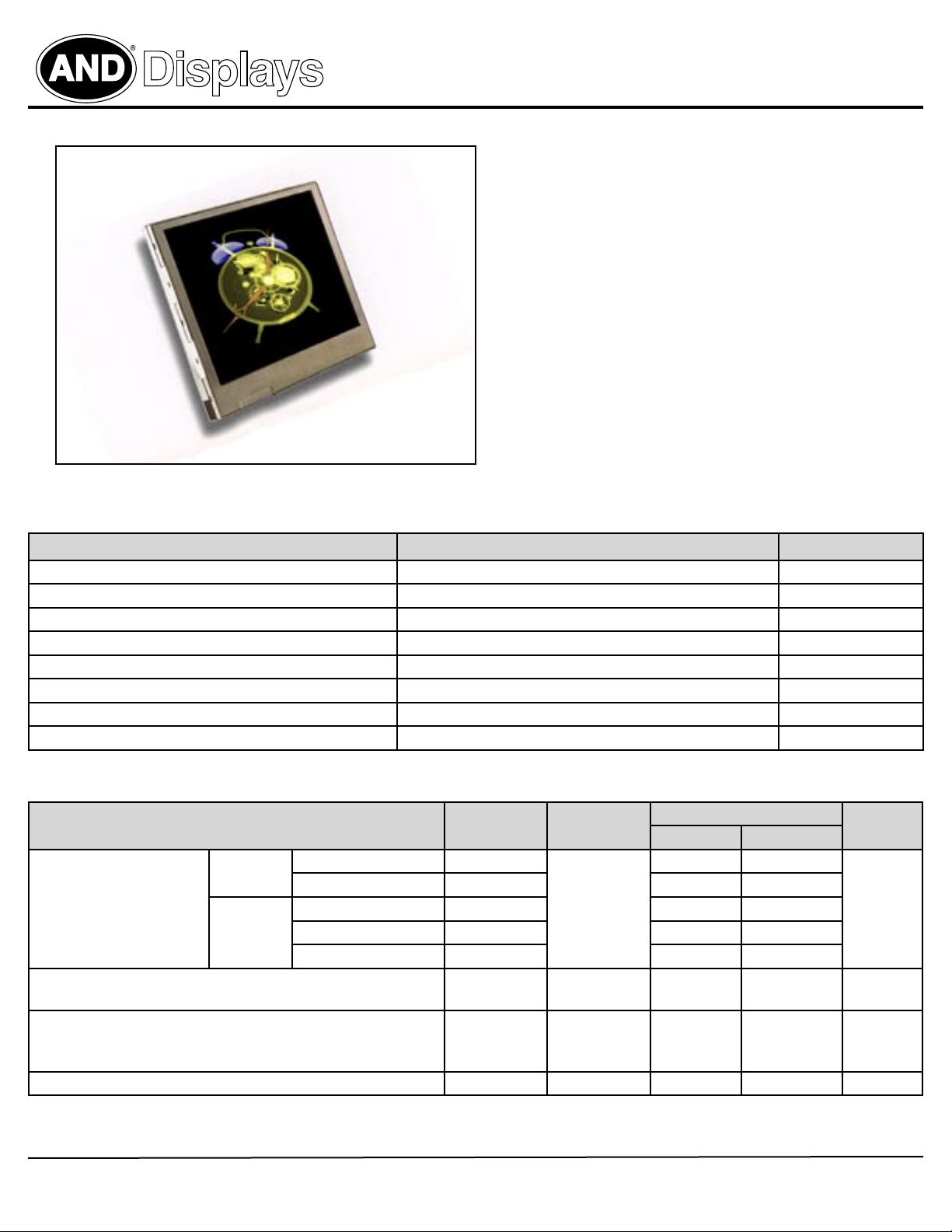
AND-TFT-35XS-LED
TFT LCD Color Monitor
AND-TFT-35XS-LED
3.5” TFT LCD
LCD Color Module
The AND-TFT-35XS-LED is a compact full color TFT LCD module, that
is suitable for camcorder, digital camera applications and other electronic
products which require high quality flat panel displays. This device consists of
a twisted nematic (TN) liquid crystal cell, that incorporates a TFT-array
that has 320 x 234 pixels on a 3.5 inch diagonal screen, X and Y drivers, an
LSI controller, and a built-in LED backlight.
Features
• Long life LED backlight
• No controller chip is necessary
• Compatible with NTSC or PAL system (switchable)
• High Resolution: 112,320 dots
• Optimum viewing direction: 6 o’clockSurface
• Up/Down and Left/Right image inversion
• Transmissive Type
• RoHS complliant
Mechanical Characteristics
Item Standard Value Unit
Screen size 3.5 inch (diagonal) –
Outline Dimensions 83.5 (W) x 63.1 (H) x 3.6 (D) mm
Active Area 71.6 (W) x 52.65 (H) mm
Surface Treatment Anti-Glare –
Pixel Number (RBG trio) 320 (W) x 234 (H) –
Pixel Configuration Delta –
Dot Pitch 0.074 (W) x 0.225 (H) mm
Weight 58 ± 5 g
Absolute Maximum Ratings: GND = 0V, Ta = 25ºC
Item Symbol Conditions Absolute Maximum Rating Unit
Min. Max.
for Source
Driver
Supply Voltage
for Gate
Driver
Analog Input Voltage
( means VR, VG, VB )
Operating Temperature
(Define that contrast, response time, other display optical characters
are Ta = +25)
Storage Temperature T
Analog AV
Digital V
Positive V
Negative V
VGH - V
V
DD
GH
GL
VIDEO
T
OP
STG
DD
-0.3 +7.0
-0.3 +7.0
Ta = 25º C
-0.3 +45
-.23 +0.3
GL
+15 +40
-0.3 +7.3 V
– 0 +60 º C
– -20 +70 º C
V
Product specifications contained herein may be changed without prior notice.
I
Purdy Electronics Corporation • 720 Palomar Avenue • Sunnyvale, CA 94085
1
Tel: 408-523-8200 • Fax: 408-733-1287 • sales@purdyelectronics.com • www.purdyelectronics.com
01/24/10
Displays
AND-TFT-35XS-LED
TFT LCD Color Monitor
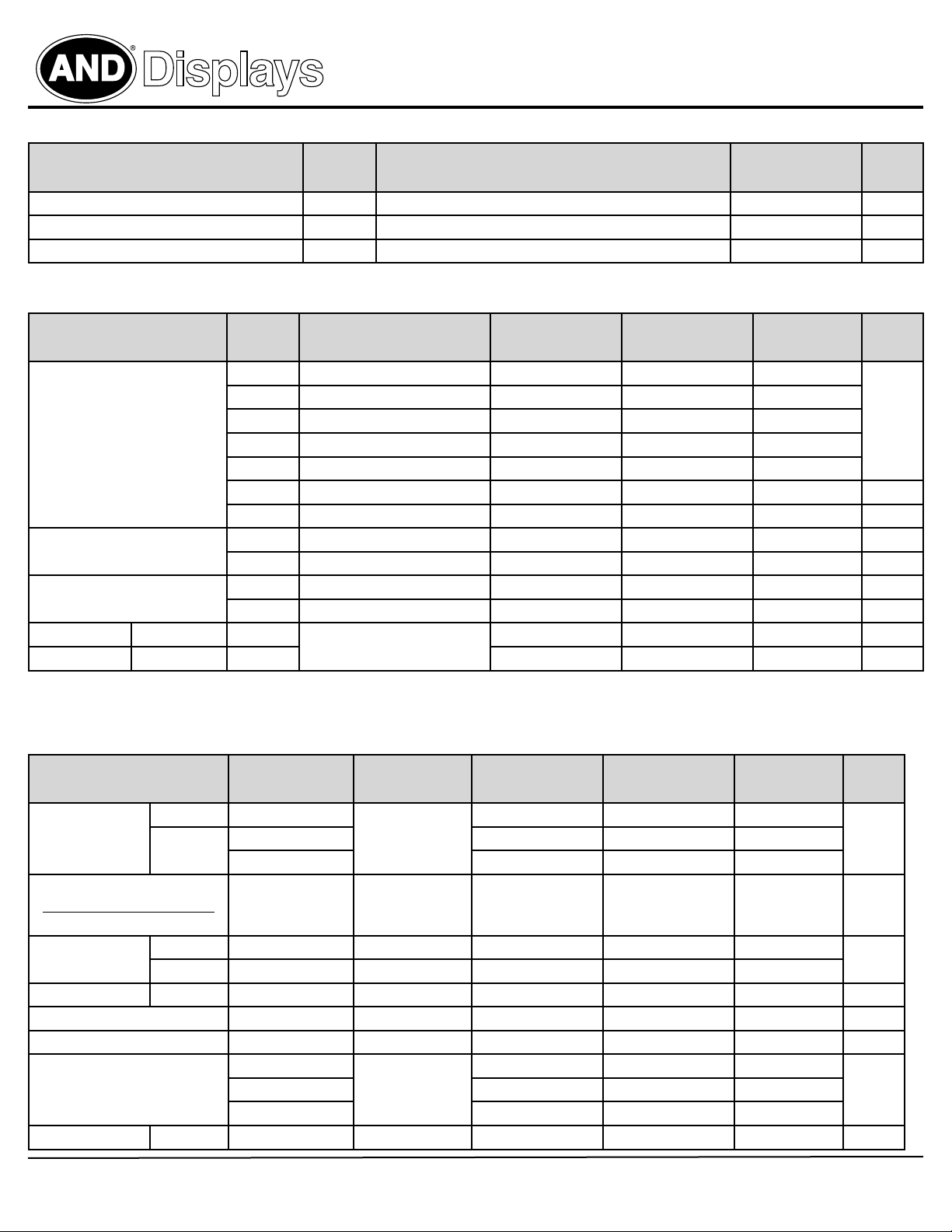
Power Consumption (Ta = 25ºC)
Item Symbol Remarks Specifications
LCD Panel Power Consumption – Power consumption for backlight is not included 33.5 mW
Backlight Lamp Power Consumption – calculated by IL x V
Total Power Consumption – – 0.69 W
Recommended Operating Conditions
Item Symbol Remarks
Min.
V
CC
V
DD
AV
Power Supply
(Ta = 25 ºC)
Video Signal (VR, VG, VB) V
V
COM
H Level V
L Level V
V
V
V
V
V
V
COM AC
V
COM DC
DD
GH
EE
GL AC
GL DC
I AC
I DC
IH
IL
AC Component of V
DC Component of V
GL
GL
AC Component, Note 2 – +4.0 +4.2 V
DC Component – +2.5 – V
AC Component of V
DC Component of V
COMM
COMM
Note 1 +0.7 V
Note 1: STH1, STH2, CPH1, CPH2, CPH3, Q2H, INH, CPV, XOE, DIO1, DIO2
Note 2: Both NTSC & PAL system Video Signal input waveform is based on 8 steps gray scale.
+4.5 +5.0 +5.5
+3.0 +3.3 +3.6
+4.5 +5.0 +5.5
+14.5 +15.0 +15.5
-15.5 -15.0 -14.5
-12.5 -11.0 -9.5 V
+0.9 +1.0 +1.1 V
Backlight Connector: JST BHR-03VS-1
Units
Typ.
L
Specifications
0.65 W
Units
Typ. Max.
– +6.0 – V
– +6.0 – V
DD
– – +0.3 V
– – V
DD
V
P-P
P-P
P-P
V
Recommended Operating Conditions
Item Symbol Remarks
Min.
Horizontal
Viewing Angle
Vertical θ (to 12 o’clock) 10 15 –
Contrast Ratio
Luminance when LCD is white
Luminance when LCD i black
Response Time Rise Tr θ = 0º – 15 30 ms
Fall Tf φ = 0º – 25 50
Transmission Ratio T – 7.5 8.0 8.5 %
Uniformity U – 65 70 – –
Brightness LUM – 200 250 – cd/m
White Chhromaticity
Lamp Life Time +25 ºC – decay to 75% 10,000 – – hr
2
Tel: 408-523-8200 • Fax: 408-733-1287 • sales@purdyelectronics.com • www.purdyelectronics.com
θ
± 45 ± 50 –
CR ≥ 10
θ (to 6 o’clock) 30 35 –
At optimized
CR
viewing angle
X
Y 0.310 0.340 0.370
θ = 0º
110 150 – –
0.280 0.310 0.340
Tc 6650 6850 7050
Purdy Electronics Corporation • 720 Palomar Avenue • Sunnyvale, CA 94085
Specifications
Typ. Max.
Units
deg
2
–
01/24/10

Displays
AND-TFT-35XS-LED
TFT LCD Color Monitor
Interface Pin Assignment
Pin No. Symbol Function Input/Output Remarks
1 STH1 Start pulse for source driver I/O Note 1
2 AV
3 AV
4 V
5 V
6 V
SS
DD
B
G
R
7 VSS Digital GND I
8 V
DD
9 CPH1 Sampling and shift clock for source driver I
10 CPH2 Sampling and shift clock for source driver I
11 CPH3 Sampling and shift clock for source driver I
12 STH2 Start pulse for source driver I/O Note 1
13 Q2H Video input rotation control I
14 INH Output enable for source driver I
15 R/L Left/Right Control for source driver I
16 V
17 V
COM
COM
18 XOE Output enable for gate driver I
19 CPV Clock input for gate driver I
20 U/D Up/Down Control for gate driver I
21 DIO2 Vertical start pulse I/O Note 5
22 DIO1 Vertical start pulse I/O Note 5
23 V
24 V
25 V
26 V
27 V
GL
EE
SS
CC
GH
28 NC No connection –
Analog GND for source driver I –
Analog power input for source driver I Note 2
Videoinput B I Note 4
Video input G I Note 4
Video input R I Note 4
Digital power input I Note 3
Common electrode voltage I Note 4
Common electrode voltage I Note 4
Gate off voltage (alternative every 1-H) I Note 4
Gate driver negative voltge I Note 6
GND I
Logic power for gate driver I Note 3
Gate on voltage I Note 7
Note 1: STHL, STHR, and R/L Mode
R/L STHL STHR Remarks
High (VDD) Input Output Left to Right
Low (0 Volt) Output Input Right to Left
Note 5: DIO1, DIO2 and U/D Mode
U/D DIO1 DIO2 Remarks
High (VDD) Input Output Down to Up
Low (0 Volt) Output Input Up to Down
Purdy Electronics Corporation • 720 Palomar Avenue • Sunnyvale, CA 94085
3
Tel: 408-523-8200 • Fax: 408-733-1287 • sales@purdyelectronics.com • www.purdyelectronics.com
Note 2: AVDD = +5V (Typ.)
Note 3: VDD, VCC = +5V (Typ.)
Note 4: VCOM = 6V
PP
Note 6: VEE = -15V (Typ.)
Note 7: VGH = -15V (Typ.)
01/24/10

Displays
Dimensional Outline:
AND-TFT-35XS-LED
TFT LCD Color Monitor
Purdy Electronics Corporation • 720 Palomar Avenue • Sunnyvale, CA 94085
4
Tel: 408-523-8200 • Fax: 408-733-1287 • sales@purdyelectronics.com • www.purdyelectronics.com
01/24/10
 Loading...