


AND-TFT-25XS-LED-KIT
AND-TFT-25XS-LED-KIT
160 x 234 Pixels
LCD Color Monitor
The AND-TFT-25XS-LED-KIT is a compact full color TFT
LCD module, that is suitable for applications such as a
camcorder, digital camera application and other electronics
products which require high quality flat panel displays. This
device consists of a twisted nematic (TN) liquid crystal cell, that
incorporates a TFT-array that has 160 x 234 pixels on a 2.45 inch diagonal
screen, X and Y drivers, an LSI controller, and a built-in LED backlight.
Features
• Long Life LED Backlight
• Ultra Compact
• Compatible with NTSC or PAL system
• DC/DC, LED Driver, Video Decoder all in one
• High Resolution: 112,320 dots
• Optimum Viewing Direction: 6 o’clock
• Up/Down and Left/Right Image Reversion
• Accepts Analog RGB input
• Applications: camcorder, digital camera applications
Mechanical Characteristics
Item
Specification Unit
Screen Size 2.45 inch (6.4 cm) diagonal inch
Display Format 160 x 234 dot
Active Area 49.68 (W) x 37.44 (H) mm
Dot Pitch 0.1025 (W) x 0.163 (H) mm
Pixel Configuration Delta –
Outline Dimension 60.6 (W) x 48.4 (H) x 3.45(D) mm
Weight 20 ± 3 g
Surface Treatment Anti-Glare –
Birghtness 250
Absolute Maximum Rating (GND = 0V, Ta = 25
Symbol
Supply Voltage for
Source Driver
Supply Voltage for
Gate Driver
Item
Analog
Digital
Positive
Negative
V
GH
Operating Temperature
°C)
AV
V
V
V
DD
DD
GH
GL
- V
GL
Absolute Maximum Rating
Min. Max.
-0.3 +7.0 V
-0.3 +7.0 V
-0.3 +45 V
-23 +0.3 V
+15 +40 V
Unit Remarks
– 0 +60 ºC Note 2
Storage Temperature – -20 +70 °C
Analog input voltage
Note 1: Analog Input Voltage means V
, V
R
V
Video
, V
G
B
-0.3 +7.3 V Note 1
Note 2: Operating Temperature define that contrast, response time, other display optical character are Ta=+25.
cd/m
2
Product specifications contained herein may be changed without prior notice.
It is therefore advisable to contact Purdy Electronics before proceeding with the design of equipment incorporating this product.
6/27/08
Tel: 408.523.8200 • Fax: 408.733.1287 • sales@purdyelectronics.com • www.purdyelectronics.com
Purdy Electronics Corporation • 720 Palomar Avenue • Sunnyvale, CA 94085
1

)
V
AND-TFT-25XS-LED-KIT
Electrical Characteristics - Recommended Operating Conditions
Item
Power Supply
Video SIgnal
(V
, V
, V
R
G
B
V
COM
H Level
L Level
Symbol
V
CC
V
DD
AV
DD
V
GH
V
EE
V
GL AC
V
GL DC
V
I AC
V
I DC
V
COM AC
V
COM DC
V
IH
V
IL
Min. Typ. Max.
+4.5 +5.0 +5.5 V
+3.0 +3.3 +3.6 V
+4.5 +5.0 +5.5 V
+14.5 +15.0 +15.5 V
-15.5 -15.0 -14.5
-12.5 -11.0 -9.5 V
+0.9 +1.0 +1.1 V
+0.7 V
Note 1: STH1, STH2, CPH1, CPH2, CPH3, Q2H, INH, CPV, XOE, DIO1, DIO2
Note 2: Both NTSC and PAL system Video Signal input waveform is based on 8 steps gray scale.
Specifications
– +6.0 –
– +4.0 +4.2 V AC Component Note 2
– +2.5 – V DC Component
– +6.0 –
DD
––
––V
+0.3 V
DD
Unit Remarks
V
V
P-P
AC Component of V
DC Component of V
V
AC Component of V
P-P
DC Component of V
Note 1
GL
GL
COM
COM
Current Consumption (GND = AV
SS
= 0V)
Item Symbol Condition
Current for Driver
Note: Ta = 25º C
AI
I
GH
I
GL
I
CC
I
DD
I
EE
DD
V
V
V
AV
V
V
GH
GL
CC
DD
DD
EE
=+15V
=-12V
=-15V
Backlight Driving & Power Consumption
Pin No.
Symbol Description Remark
29 GLED Supply Current for LED
30 VLED Supply voltage for LED
Note 3: Supply voltage for LED would depend on supply current.
Parameter
Supply Voltage
Supply Current
Symbol Min. Typ. Max. Unit Remarks
V
L
I
L
Specifications
Min. Typ. Max.
Unit Remarks
– 0.1 0.2 mA
V
center voltage
GL
=+5V
=+5V
=+5V
– 0.36 0.9 mA
– 0.2 0.4 mA
– 3.5 5.0 mA
– 0.6 1.5 mA
– 0.3 0.6 mA
I
L
V
; Note 3
L
I
–17– V
= 20 mA
L
–20–mA
2
Tel: 408.523.8200 • Fax:408.733.1287 • sales@purdyelectronics.com • www.purdyelectronics.com
Purdy Electronics Corporation • 720 Palomar Avenue • Sunnyvale, CA 94085
6/27/08

Block Diagrams
.
θ CR ≥
θ
θ
θ
θ
AND-TFT-25XS-LED-KIT
Power Consumption
Item
LCD Panel Power Consumption – 31.82 mW Note 5
Backlight Lamp Power Consumption – 0.34 W Note 6
Total Power Consumption – 0.372 W –
Note 5: The power consumption for backlight is not included
Note 6: Backlight power consumption is calculated by I
x V
L
L
Optical Specification
Item
Symbol Condition Min. Typ. Max. Unit
Horizontal
Viewing Angle
Vertical
(to 12 o’clock) 10 15 – deg
(to 6 o’clock) 30 35 – deg
Contrast Ratio CR
Response Time
Rise
Fall
T
r
T
f
Transmission Ratio T 7.3 7.8 8.3 %
Uniformity U 65 70 –
Brightness 200 250
White Chromaticity
X
Y 0.300 0.330 0.360
– 1000 5000 hrs
Note 5: The power consumption for backlight is not included
x V
Note 6: Backlight power consumption is calculated by I
.
L
L
Symbol Typ. Unit Remark
10
At optimized view-
ing angle
= 0º
= 0º
± 45 ± 50 – deg
200 350 – –
–1530–
–2550ms
2
cd/m
0.280 0.310 0..340
6/27/08
Tel: 408.523.8200 • Fax:408.733.1287 • sales@purdyelectronics.com • www.purdyelectronics.com
Purdy Electronics Corporation • 720 Palomar Avenue • Sunnyvale, CA 94085
3

AND-TFT-25XS-LED-KIT
Pin Description: J201 LCD Panel Input/Output Terminals
Pin No.
1 STH1 Start pulse for source driver I/O Note 1
2
3
4
5
6
7
8
9 CPH1 Sampling and shift clock for source driver I
10
11
12 STH2 Start pulse for source driver I/O Note 1
13 Q2H Video input rotation control I
14 INH Output enable for sourec driver I
15 R/L Left/Right Control for source driver I Note 1
16
17 XOE Output enable for gate driver I
18 CPV Clock input for gate driver I
19 U/D Up/Down Control for gate driver I
20 DIO2 Vertical start pulse I/O
21 DIO1 Vertical start pulse I/O
22
23
24
25
26
27
28
29
30
Note 1: STH1, STH2 and R/L mode
R/L STH1 STH2 Remarks
High (VDD) Input Output Left to Right
Low (0 Volt.) Output Input Right to Left
Note 2: AV
Note 3: V
Note 4: V
Symbol Function Input/Output Remarks
AV
SS1
AV
DD
V
B
V
G
V
R
V
SS
V
DD
CPH2
CPH3
V
COM
V
GL
V
EE
V
SS
V
CC
V
GH
NC
NC
GLED
VLED
Analog GND for source driver I
Analog power input for source driver I Note 2
Video Input B I
Video Input G I
Video Input R I
Digital GND I
Digial power input I Note 3
Sampling and shift clock for source driver I
Sampling and shift clock for source driver I
Common electrode voltage I Note 4
Gate off voltage (alternative every 1-H) I Note 4
Gate driver negative voltage I Note 6
GND I
Logic power for gate driver I Note 3
Gate on voltage I Note 7
No connection –
No connection –
Supply current for LED – Note 8
Supply voltage for LED – Note 9
Note 6: V
Note 7: V
= -15V (Typ.)
EE
= +15V (Typ.)
GH
Note 8: GLED = 20mA (Typ.)
Note 9: VLED = +17V (Typ.)
= +5V (Typ.)
DD
, V
DD
COM
= +5V (Typ.)
CC
= 6V
PP
Note 4
Note 5
Note 5: DIO1, DIO2 and U/D mode
U/D
DIO1 DIO2 Remarks
High (VDD) Input Output Down to Up
Low (O Volt.) Output Input Up to Down
4
Tel: 408.523.8200 • Fax:408.733.1287 • sales@purdyelectronics.com • www.purdyelectronics.com
Purdy Electronics Corporation • 720 Palomar Avenue • Sunnyvale, CA 94085
6/27/08

AND-TFT-25XS-LED-KIT
Input/Output Connector, LCD Module Connector, FFC Down Connector, 30 pins Pitch: 0.5 mm
Timing Characteristics of Input SIgnal
Characteristics Symbol Min. Typ. Max. Unit Remarks
1 Field Scanning Period t1V – 262.5 – H
1 Line Scanning Period t1H – 63.5 –
Source Driver Operating Frequency fhc 1.0 3.14 5.0 MHz
Signal Sampling Pulse Width tchw 200 317.7 1000 ns
Signal Sampling Pulse Delay tchd 95.3 105.9 116.5 ns tchd 12, 23
Signal Sampling Pulse Width (H) tchwh 142.9 158.8 174.7 ns
Signal Samplin Pulse Delay (L) tchwl 14.29 158.8 174.7 ns
Source Start Signal Pulse Width tshw 90 317.7 630* ns *tshset=tshhld
Source Start Signal Setup Time tshset 20 158.8 – ns
Source Start Signal Hold Time tshhld 20 158.8 – ns
Source Output Enable Pulse Width tohw 1.0 2.0 –
Source Start Signal Rising Time tss – 9.8 –
Video Input Signal Start Point tvs – 10.0 –
Phase Difference Between OEH & CPV toc 1.5 2.3 –
Gate Clock Period tcvw 10 63.5 –
Gate Clock Pulse WIdth (H) tcvwh 10 31.7 48
Gate Clock Pulse Width (L) tcvwl 10 31.7 48
Gate Start Signal Pulse Width tsvw 5 63.5 126**
Gate Start Signal Setup Time tsvset 5 53.2 –
Gate Start Signal Hold Time tsvhold 5 10.3 –
Phase Difference Between OEH & STH tosp – 4 –
Phase Difference Between SYNC & OEH tohs – 1.4 –
Gate Output Enable Pulse Width toev – 2.5 –
Delay Time t
V
COM
RGB Delay Time
DCOM
t
DRGB
––3
––2
Vertical Display Start tsv – 3 – tH
s
s
s
s
s
s
s
s
s **tsvset=tsvhld
s
s
s
s
µ
s
µ
s
µ
s
µ
µ
µ
µ
µ
µ
µ
µ
µ
µ
µ
µ
µ
6/27/08
Tel: 408.523.8200 • Fax:408.733.1287 • sales@purdyelectronics.com • www.purdyelectronics.com
Purdy Electronics Corporation • 720 Palomar Avenue • Sunnyvale, CA 94085
5

Dimensional Outline
AND-TFT-25XS-LED-KIT
6
Tel: 408.523.8200 • Fax:408.733.1287 • sales@purdyelectronics.com • www.purdyelectronics.com
Purdy Electronics Corporation • 720 Palomar Avenue • Sunnyvale, CA 94085
6/27/08
PC-TFT-25XS
Interface Board
AND-TFT-25XS-LED-KIT
Features
• Used for TFT-LCD display: 2.5” AND-TFT-25XS-LED
• Compatible with NTSC or PAL system
The PC-TFT-25XS is designed to work with the
AND-TFT-25XS-LED color TFT display which is
suitable for camcorders, digital camera
applications and other electronic products which
• High Resolution: 112,320 dots
• Optimum Viewing Direction: 6 o’clock
• Up/Down and Left/Right Image Reversion
Mechanical Characteristics
Item Specification Unit
Screen Size 2.45 (diagonal) inch
Surface Treatment Anti-Glare –
Display Format 160 x 234 dot
Active Area 49.68 (W) x 37.44 (H) mm
Dot Pitch 0.1035 (W) x 0.160 (H) mm
Pixel Configuration Stripe –
Outline Dimension 60.6 (W) x 48.4 (H) x 3.45 (D) mm
Weight 20 ± 3 g
Contrast Ratio 350:1
View Angle (V) +15 ºC / -35ºC (H) ± 50ºC
Color Full Color
Brightness 250 cd/m2
Please refer to data sheet for AND-TFT-25PXS-LED for more details on panel information.
require high quality flat panel displays.
Absolute Maximum Rating
Item Symbol
Input Voltage
Input Voltage Vin +4 +6 V
Video Input Signal Video in 0.5 2.0 Vp-p Note 1
Digital Input Signal TTL +0.3 +5.3 V
Operating Temperature -10 60 ºC
Relative Humidity 5 90 %RH
Storage Temperature -25 80 ºC
Relative Humidity 0 90 %RH
Supply Voltage
Supply Current
Note 1: @ 75 Ω
6/27/08
Tel: 408.523.8200 • Fax:408.733.1287 • sales@purdyelectronics.com • www.purdyelectronics.com
Purdy Electronics Corporation • 720 Palomar Avenue • Sunnyvale, CA 94085
Vin
V
I
L
L
Specifications
Min. Max.
+8 +16
– 13.2 V IL=20mA
–20mA
Unit Remarks
V
7

AND-TFT-25XS-LED-KIT
Electrical Characteristics - Operating Conditions
Item Symbol I/O
Input Voltage Vin
Total Current Iin
I +10 +12 +14 V
I 153 mA
Power Consumption I 1.84 W @+12V
Input Voltage Vin
Total Current Iin
Power Consumption
Video Input Signal Video in
Output Voltage +5V
Brightness Adjust Bright
Contrast Adjust Contrast
Color Adjust Color
Tint Adjust Tint (NTSC only)
Viedo Auto Detect NTSC/PAL
I+4 +5 +6 V
I 300 mA
I 1.5
I -1.0 Vp-p
O – +5V
I +1.13 +1.3 +1.43 V
I +2.10 +2.57 +2.98
I +2.26 +2.72 +3.59 V
I
O – TTL V
Specifications
Min. Typ. Max.
+1.5
+3.09 +4.6 V
Unit Remarks
W @+5V
@ 75 Ω
V
V
Current Consumption (GND = AVSS = 0V)
Item White Window Red Green Blue Remark
S/N: 001 x
y
L
TC
0.307
0.326
300 (cd/m
8650(ºK)
0.558 0.340 0.161
0.349 0.541 0.128
2
)
– – – ± 15%
–––
Note 1. Luminance: BM-7 FAST (TOPCON)
Note 2. Pattern Generator: FLUKE PM54200
Note 3. Measurement Distance: 500mm ± 500mm
Note 4. TOPCON BM-7 Luminance Meter 2º field of view is used in the testing (After 10 min ~ 20 min Operation)
LED Driver Data: Ta - 25ºC @+5V
Item Symbol
Supply voltage of LED backlight
Supply current of LED backlight
V
L
I
L
Specifications
Min. Typ.
– 13.8 V
– 23.3 mA
Unit Remark
I
= 23.3 mA
L
8
Tel: 408.523.8200 • Fax:408.733.1287 • sales@purdyelectronics.com • www.purdyelectronics.com
Purdy Electronics Corporation • 720 Palomar Avenue • Sunnyvale, CA 94085
6/27/08
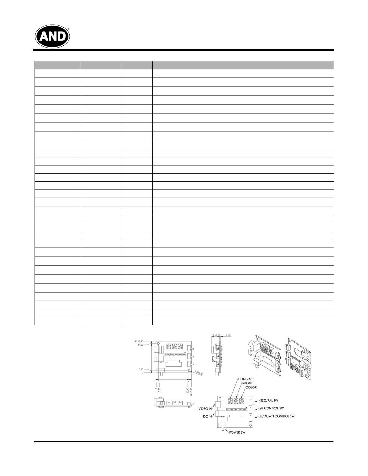
Terminal Pin Assignment
Pin No. Symbol I/O Description
1 STH I/O Start pulse for source driver
2
3
4
5
6
7
8
AV
AV
SS
DD
V
B
V
G
V
R
V
SS
V
DD
I Analog GND for source driver
I Analog power input for source driver
I Video Input B
I Video Input G
I Video Input R
I Digital GND
I Digital power input
9 CPH1 I Sampling and shift clock for source driver
10 CPH2 I Sampling and shift clock for source driver
11 CPH3 I Sampling and shift clock for source driver
12 STH2 I/O Start pulse for source driver
13 Q2H I Video input rotation control
14 INH I Output enable for source driver
15 R/L I Left/Right Control for source driver
16
V
COM
I Common electrode voltage
17 XOE I Output enable for gate driver
18 CPV I Clock input for gate driver
19 U/D I Up/Down Control for gate driver
20 DIO2 I/O Vertical start pulse
21 DIO1 I/O Vertical start pulse
22
23
24
25
26
V
GL
V
EE
V
SS
V
CC
V
GH
I Gate off voltage (alternative every 1-H)
I Gate driver negative voltage
I GND
I Logic power for gate driver
I Gate on voltage
27 NC – No connection
28 NC – No connection
29 GLED Supply current for LED
30 VLED Supply voltage for LED
AND-TFT-25XS-LED-KIT
2535 Demo Board
6/27/08
Tel: 408.523.8200 • Fax:408.733.1287 • sales@purdyelectronics.com • www.purdyelectronics.com
Purdy Electronics Corporation • 720 Palomar Avenue • Sunnyvale, CA 94085
9

AND-TFT-25XS-LED-KIT
J301: Pin Assignment of SIgnal Input (Pitch 1.25 mm 15P, Side Entry Type)
Pin No. Symbol I/O Description Remarks
1 Vin I +12 V Voltage Power supply
2 GND – Power Ground
3 GND – Power Ground
4 GND – Signal Ground
Ω
5 Video-IN I Video input (1Vp-p/75
6 +5V O Voltage DC Output Note 1
7 Bright I Brightness control
8 Contrast I Contrast control
9 Color I Color control
10 Tint I Tint control Note 2
11 NTSC/PAL O Systemm Auto detect output Note 3
12 LRC I Screen Left / Right reverse Note 4
13 UDC I Screen Up / Down reverse Note 4
14 Dimmer I Backlight brightness control
15 Enable I Backlight On/Off Note 5
Note 1: The +5V power supply external control circuit. (Max. output is 10mA)
Note 2: The TINT is only operating in NTSC system.
Note 3: The output High level for NTSC mode and Low level for PAL mode.
Note 4: Default +5V or floating is normal scanning and 0V is for reversed scanning.
Note 5: The floating or 0V is backlight on and 5V is backlight off.
Block DIagram
)
10
Tel: 408.523.8200 • Fax:408.733.1287 • sales@purdyelectronics.com • www.purdyelectronics.com
Purdy Electronics Corporation • 720 Palomar Avenue • Sunnyvale, CA 94085
6/27/08

AND-TFT-25XS-LED-KIT
6/27/08
Tel: 408.523.8200 • Fax:408.733.1287 • sales@purdyelectronics.com • www.purdyelectronics.com
Purdy Electronics Corporation • 720 Palomar Avenue • Sunnyvale, CA 94085
11
 Loading...