

Purdy AND711AST-30-EO User Manual
≤
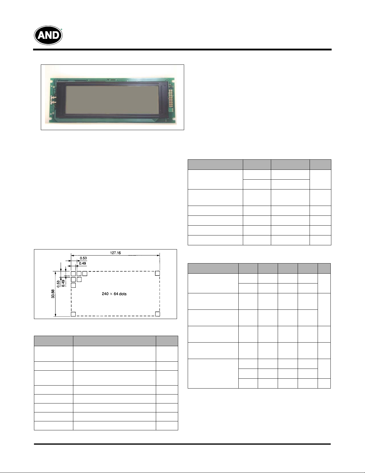
AND711AST-30/-EO
240 x 64 Dots
Intelligent Graphic Display
The AND711AST-30/-EO is a full dot matrix LCD module
including an LCD controller and display RAM. This device
can display graphic patterns and symbols and is suitable for
a message display for various instruments such as business
machine terminals.
Features
• RoHS Compliant
• Super twist
• 40 character x 8 line capability
• Excellent readability and high contrast ratio
• 8-bit parallel bus for read/write data by CPU interface
• Built-in LCD controller and display RAM (8k byte)
• Character mode, graphic mode, and character and graphic
combination mode
• RoHS compliant
• Wide operating temperatures range (0°C to + 50°C)
• Compact and easily mounted on any equipment
• User-selectable font–6 x 8 or 8 x 8
• Available with EL backlighting attached (-EO option)
Dot Matrix Dimensions
Mechanical Characteristics
Item
Outline
Dimensions
Specification Unit
180 (W) x 65 (H) x 10 (D) mm
Number of Dots 240 (W) x 64 (H)
# of Characters
40 x 8 (320) Characters
6 x 8 dot format, alpha-numeric
Viewing Area 132 (W) x 39 (H) mm
Bezel Opening 132 (W) x 39 (H) mm
Dot Size 0.49 (W) x 0.49 (H) mm
Dot Pitch 0.53 (W) x 0.53 (H) mm
Weight (approx.) I20/150 (ST/EO) gram
Absolute Maximum Ratings
Item
Supply Voltage
EL Drive Voltage
(f
= 1 kHz)
EL
Input Voltage
Operating Temperature
Storage Temperature
EL Driving Freq. (EO)
Symbol Rating Unit
V
DD
V
EE
V
EL
V
IN
T
op
T
stg
f
EL
5.5
-19
130
–.3 ≤ V
+.3
IN
0 to +50 °C
-20 to +70 ˚C
1 kHz
Electrical Characteristics (TA = 25°C)
Item
Supply Voltage
High Level In Voltage
(V
= 5.0V)
DD
Low Level In Voltage
(V
= 5.0V)
DD
High Level Output Volt.
(V
= 5.0V)
DD
Low Level Output Volt.
(V
= 5.0V)
DD
Power Consumption
1. All dots on. (V
2. mA rms
Symbol Min. Typ. Max. Unit
DD
V
V
V
V
V
V
I
DD
(1)
I
EE
I
EL
=
.5V,
V
EE
4.5 5.0 5.5
DD
–5.75 –8.5 –11.5
EE
2.8 – 5
IN
IL
OH
OL
– – 0.8
V
DD
–0.3
– – 0.3 V
– 16.0 25.0
– 2.4 3.0
– 4.0 10
=
–8.5V, V
=110, f
EL
––V
= 500 Hz or at Typ.)
EL
Product specifications contained herein may be changed
without prior notice. It is therefore advisable to contact
Purdy Electronics before proceeding with the design of
equipment incorporating this product.
V
V
rms
V
V
V
mA
(2)
1
Tel: 408.523.8200 • Fax: 408.733.1287 • sales@purdyelectronics.com • www.purdyelectronics.com
Purdy Electronics Corporation • 720 Palomar Avenue • Sunnyvale, CA 94085
7/20/07

V
EE
V
DD
GND
LCD Module
R1
R2
R1 = 10k, R2 = 10k, TR 2SA1102 or equivalent
T
R
t
CDS
tCP,tRD,t
WP
t
ACC
t
CDH
t
DH
t
OH
t
DS
C/D
CE
RD, WR
D0-D7
(WRITE)
D0-D7
(READ)
AND711AST-30/-EO
Intelligent Graphics Display
Optical Characteristics (TA = 25˚C, φ = 0°, θ = 0)
Item
Viewing Angle
Symbol Min. Typ. Max. Unit
Right to Left – 80 –
Up & Down – 55 –
degree
Contrast K 2.5 4.8 - -
Turn On
Turn Off
T
on
T
off
- 200 350 ms
- 250 300 ms
Note: Refer to Applications Section for definitions of viewing
angle, contrast ratio, response time (on and off) and
luminance.
Connector Pin Assignment
Pin No.
Signal Function
1 FGND Frame Ground (connected to metal bezel)
2 GND Ground (signal)
3
4
5WR
6RD
7CE
V
Power Supply for logic (5V)
DD
V
Power Supply for LCD Drive (–8.5 ±3V)
EE
Data Write
Data Read
Chip Enable
WR = “L”, C/D = “H”: Command Write
WR
8 C/D
= “L”, C/D = “L”: Data Write
RD
= “L”, C/D = “H”: Status Read
RD
= “L”, C/D = “L”: Data Read
9 NC No connection
10 RESET
Controller Reset (Active Pullup Required)
11 D0 Data Input/Output
12 D1 Data Input/Output
13 D2 Data Input/Output
14 D3 Data Input/Output
15 D4 Data Input/Output
16 D5 Data Input/Output
17 D6 Data Input/Output
18 D7 Data Input/Output
19 FS
Font select. Open or connect to V
Connect to ground: 8 x 8 dot
: 6 x 8 dot
DD
20 NC No connection
Power Supply
The LCD panel is driven by the voltage V
adjustable V
is required for contrast control and
EE
temperature compensation.
Temperature Variations
Temperature
0°C 13.9
+25°C 12.5
+50°C 10.8
Example of Variable Negative Voltage Supply
DD
–V
, so an
EE
V
–V
DD
EE
Timing Relationships and Diagram
Signal Timing Relationships
Item
C/D Set Up Time
C/D Hold Time
CE
,
RD
,
WR
Pulse Width
Data Set Up Time
Data Hold Time
Access Time
Output Hold Time
Timing Diagram
Symbol Min. Max. Unit
t
CDS
t
CDH
t
t
t
CE,
RD,
t
DS
t
DH
t
ACC
t
OH
WR
100 –
10 –
80 –
80 –
40 –
– 150
10 50
ns
7/20/07
Tel: 408.523.8200 • Fax: 408.733.1287 • sales@purdyelectronics.com • www.purdyelectronics.com
Purdy Electronics Corporation • 720 Palomar Avenue • Sunnyvale, CA 94085
2
 Loading...