

φ
AND671GST/GST-LED
1 Line x 16 Characters
Intelligent Character Display
The AND671GST/GST-LED devices are compact, LCD
modules that have an on-board LCD controller and driver
circuit. These devices can display 160 characters (numerals,
letters, symbols and Kana letters), as well as eight custom
characters.
Features
• RoHS Compliant
• AND671GST: Super Twist Technology
• AND671GST-LED: STN with LED backlight
• Low voltage, +5V single power supply
• Built-in controller (KS0066 or equivalent)
• 1/16 Duty Cycle
• 4.2 V LED Forward Voltage
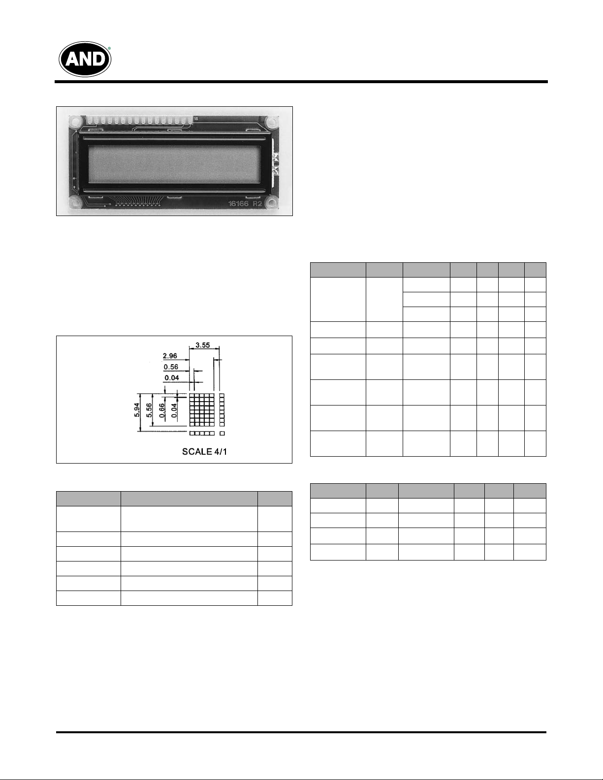
Dot Matrix Dimensions
Mechanical Characteristics
Item Specification Unit
Outline
Dimensions
80 (W) x 36 (H) x 8.8 (12.7LED) (D) mm
Character Size 2.96 (W) x 5.56 (H) mm
Character Pitch 3.55 (W) x 5.94 (H) mm
Viewing Area 65.0 (W) x 16.0 (H) mm
Dot Size 0.55 (W) x 0.66 (H) mm
Dot Pitch 0.60 (W) x 0.70 (H) mm
Electrical Characteristics (TA = 25°C)
Item
Symbol Condition Min. Typ. Max. Unit
T=0ºC – 4.8 – V
LCD Operating
Voltage
V
-V
DD
T=25ºC – 4.5 –
O
T=50ºC – 4.2 –
V
Supply Voltage
Supply Current
Input Voltage
High Level
Input Voltage
Low Level
Output Voltage
High Level
Output Voltage
Low Level
DD
-V
SS
I
DD
V
IH
V
IL
V
OH
V
OL
– 4.7 5 5.3 V
– –24mA
– 2.2 –
V
DD
– 0 – 0.6 V
– 2.4 – – V
– – – 0.4 V
Optical Characteristics (TA = 25˚C, φ = 0°, θ = 0°)
Item
Viewing Angle
Symbol Min. Typ. Max. Unit
– 50 – degree
Contrast K – 6.0 – –
Turn On
Turn Off
T
on
T
off
– 200 400 ms
– 250 400 ms
V
V
V
Product specifications contained herein may be changed without prior notice.
It is therefore advisable to contact Purdy Electronics before proceeding with the design of equipment incorporating this product.
1
Tel: 408.523.8200 • Fax: 408.733.1287 • sales@purdyelectronics.com • www.purdyelectronics.com
Purdy Electronics Corporation • 720 Palomar Avenue • Sunnyvale, CA 94085
5/26/08
Connector Pin Assignment
Pin No.
Signal Function
1
2
V
V
3
SS
DD
V
O
0V
5V
Contrast Adj.
4 RS Register Select
5 R/W
Read/Write
6 E Enable Signal
7 DBO Data Bit 0
8 DB1 Data Bit 1
9 DB2 Data Bit 2
10 DB3 Data Bit 3
11 DB4 Data Bit 4
12 DB5 Data Bit 5
13 DB6 Data Bit 6
14 DB7 Data Bit 7
15 A LED Power
16 K LED Power
AND671GST/GST-LED
Intelligent Character Display
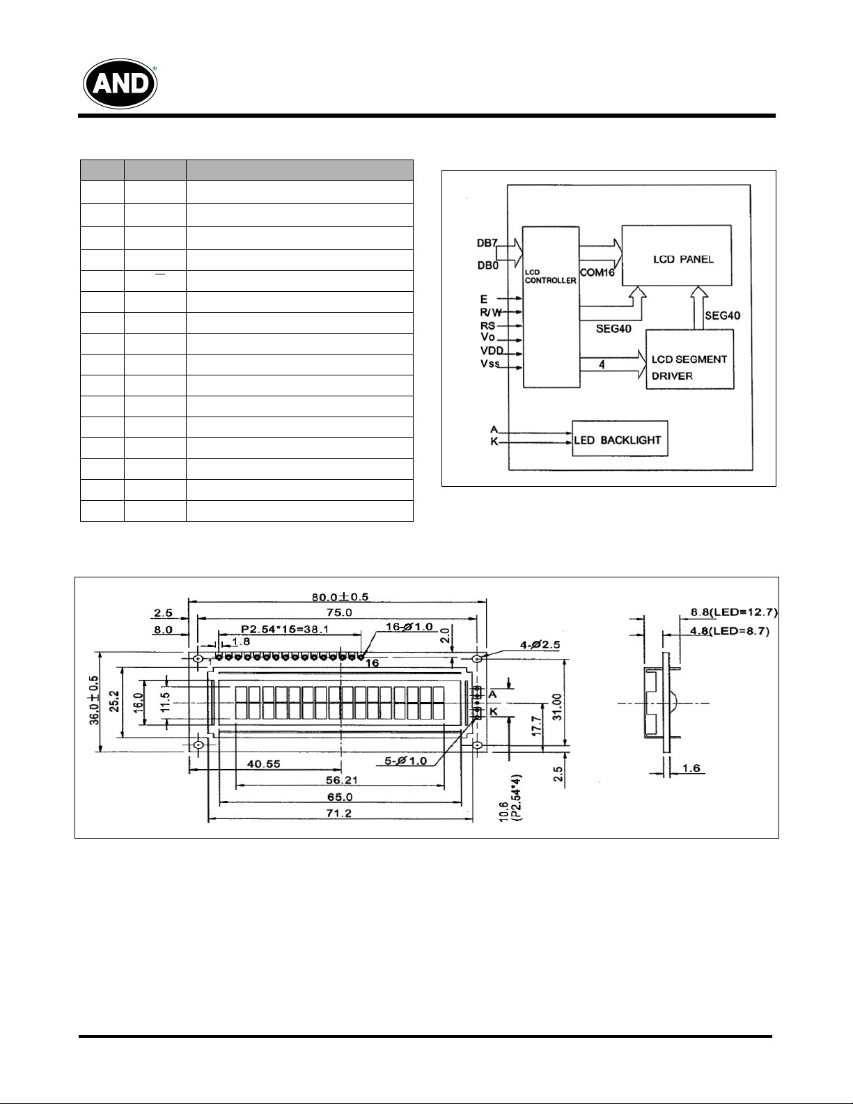
Block Diagram
Dimensional Outline
5/26/08
Tel: 408.523.8200 • Fax: 408.733.1287 • sales@purdyelectronics.com • www.purdyelectronics.com
Purdy Electronics Corporation • 720 Palomar Avenue • Sunnyvale, CA 94085
2

Absolute Maximum Ratings
Item
Power Supply Voltage
Input “H” Level Voltage
Input “L” Level Voltage
Output “H” Level Voltage
Output “L” Level Voltage
Input Leekage Current
Power Supply Current
LCD Power Supply Voltage
Symbol Condition
V
DD
V
IH1
V
IL1
V
V
V
V
I
DD
LCD
OH
OL
LI
I
OH
AC Characteristics
Item
Enable Cycle Time
Enable Pulse Width “High Level”
Enable Rise/Fall Time
Address Set-up Time RS, R/W to E
Address Hold Time
Data Set-up Time
Data Delay Time
Data Hold Time (Writing)
Data Hold Time (Reading)
Clock Oscillation Frequency
µ
= 0.2.05 mA
I
= 1.2 mA
OL
V
= 0-V
IN
DD
V
= 5V
DD
V
- V
DD
0
AND671GST/GST-LED
Intelligent Character Display
Standard Value
Min. Typ. Max.
4.5 5 5.5 V
2.2 –
V
DD
-0.3 – 0.6 V
2.4 – – V
– – 0.4 V
-1 – 1
––3mA
3––V
Symbol Min. Max. Unit
t
CVCE
p
WEH
t
ER
t
AS
t
AH
t
DSW
t
DDR
t
t
DHR
f
OSC
, t
Ef
H
500 – ns
230 – ns
–20 ns
40 – ns
10 – ns
80 – ns
– 160 ns
10 – ns
5– ns
270 (Typ.) KHz
Unit Applicable Terminal
V
DD
V
RS, R/W
, E, DB
DB
~ DB
0
, E, DB
RS, R/W
A
V
DD
V
0
~ DB
0
~ DB
0
7
7
Timing Characteristics
3
Tel: 408.523.8200 • Fax: 408.733.1287 • sales@purdyelectronics.com • www.purdyelectronics.com
Purdy Electronics Corporation • 720 Palomar Avenue • Sunnyvale, CA 94085
5/26/08

AND671GST/GST-LED
Intelligent Character Display
Display Commands
Instruction
RS R/W DB7 DB6 DB5 DB4 DB3 DB2 DB1 DB0
1: Clear Display 0 0 0 0 000001
2: Return Home 0 0 0 0 00001*
3: Entry Mode Set 0 0 0 0 0001I/DS
4: Display On/Off 0 0 0 0 0 0 1 D C B
5: Cursor/Display Shift 0 0 0 0 0 1 S/C R/L * *
6: Function Set 0 0 0 0 1 DL N F * *
7: Set CG RAM Address 0 0 0 1
8: Set DD RAM Address 0 0 1
9: Read busy flag/
address counter
01BF
10: Write data 1 0 Write Data Write data to CG or DD RAM
11: Read data 1 1 Read Data Read data from CG or DD RAM
Execution Time (Et) of Instruction: (Under condition of or f
1 & 2: Et = 1.52 ms
3 ~ 11: Et = 37 µ s
***: Either 0 or 1
Code
Description
Clears entire display & sets DD RAM address 0 in
address counter.
Sets DD RAM address 0 in address counter. Also
returns display from being shifted to original position.
DDRAM contents remain unchanged.
I/D = 1: Increment
I/D = 0: Increment
S=1: Accompanies display shift
I/D = 1/0: Display on/off
I/D = 0/1: Cursor on/off
S=1: Blink of cursor
S/C=1: Display shift
S/C = 0: Cursor move
R/L = 0: Shift to left
R/L = 1: Shift to right
DL = 1: 8 bits, DL = 0: 4 bits
N=1: 2 lines, N=0: 1 line
F=1: 5*10 dots, F=0: 5*8 dots
A
CG
A
A
DD
: DDRAM address corresponds to cursor address
DD
A
: CG RAM Address
CG
BF=1: Busy, BF=0: Not busy
A
C
A
: Address counter used for both of CG & DDRAM
C
address
= 270 KHz)
OSC
Connecting Block Diagram
5/26/08
Tel: 408.523.8200 • Fax: 408.733.1287 • sales@purdyelectronics.com • www.purdyelectronics.com
Purdy Electronics Corporation • 720 Palomar Avenue • Sunnyvale, CA 94085
4
 Loading...