

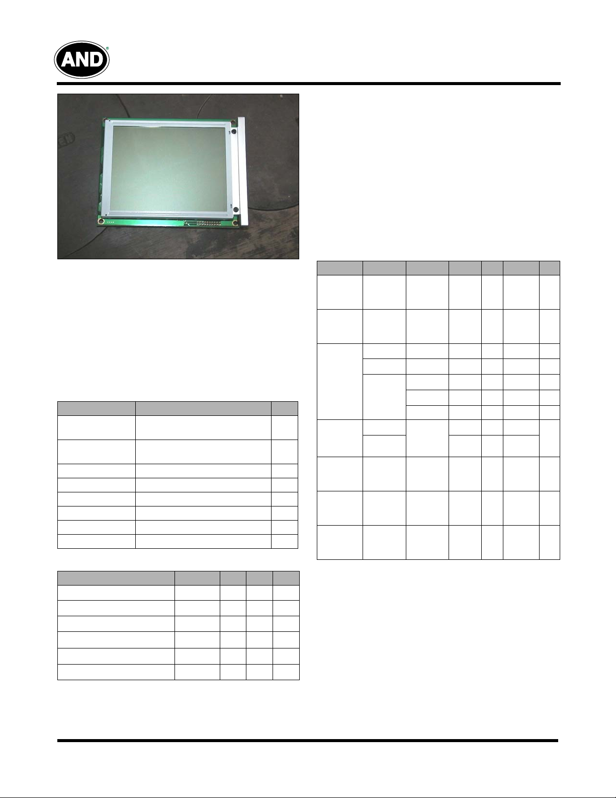
Displays
AND3222MST-LEDW
6” FSTN LCD Module
The AND3222MST-LEDW display is a compact, full dot matrix,
which is an STN gray positive LCD type, transflective rear
polarizer with a yellow green backlight color. The AND3222MSTLEDW can display TEXT information, numerals, letters and
symbols, as well as GRAPHIC patterns. These devices are
suitable for medical and measurement equipment, point-of-sale
terminals, protable equipment, and marine instrumentation.
Electrical Characteristics (Ta = 25°C)
Features
• STN Gray Positive LCD type
• Built-in LED yellow green backlight
• Excellent readability and high-contrast ratio
• 320 (W) x 240 (H) dot graphic display
• Wide operating temperature range (-20 to +70 ºC)
• Transflective rear polarizer
• 6 o’clock viewing angle
• RoHS Compliant
Mechanical Characteristics
Item
Outline
Dimensions
148.0 (W) x 120.2 (H) x 20.5 max (D) mm
Number of
Pixels
Active Area 120.14 (W) x 92.14 (H) mm
Pixel Size 0.33 (W) x 0.33 (H) mm
Pixel Pitch 0.36 (W) x 0.36 (H) mm
Duty Ratio 1/240 duty
Controller SID13305 –
DC/DC Converter With –
Specification Unit
320 (W) x 240 (H) pixels
Absolute Maximum Ratings - Electrical
Item
Power Supply for Logic
Power Supply for LCD Driver
Input Voltage
LED Power Dissipation
LED Forward Current
LED Reverse Voltage
Symbol Min. Max. Unit
- V
V
DD
V
- V
DD
V
P
AD
I
AF
V
SS
LCD
I
R
-0.3 7.0 V
0 30.0 V
-0.3 V
DD
– 1242
– 270
8V
mW
mA
Item
Power
Supply for
Logic
Power
Supply for
LCD Drive
Input
Voltage
Logic
Supply
Current
LED
Forward
Voltage
LED
Forward
Current
LED
Reverse
Current
V
Symbol Condition Min. Typ. Max. Unit
V
V
V
LCD -
V
DD -
V
V
DD -
SS
V
SS
IL
IH
V
O
– 4.5 5.0 5.5 V
– -21.6 -22.1 -22.7 V
L Level 0 – 0.6 V
H Level 2.2 –
Ta = 0ºC
Ta = 25ºC
–
–
V
DD
22.7
–
24.3 – V
Ta = 50ºC – 25.8 – V
I
I
V
=5.0V
DD
V
DD -
24.3V
If = 180 mA – 4.2 4.6 V
– – 180 – mA
VR = 8V – – 0.3 mA
V
DD
EE
I
I
F
F
R
V
=
O
34.9 31.3 –
– 3.6 –
V
V
mA
Product specifications contained herein may be changed without prior notice. It is therefore advisable to contact Purdy
Electronics before proceeding with the design of equipment incorporating this product.
5/1/08
Purdy Electronics Corporation • 720 Palomar Avenue • Sunnyvale, CA 94085
Tel: 408.523.8200 • Fax: 408.733.1287 • email@purdyelectronics.com
www.purdyelectronics.com
1
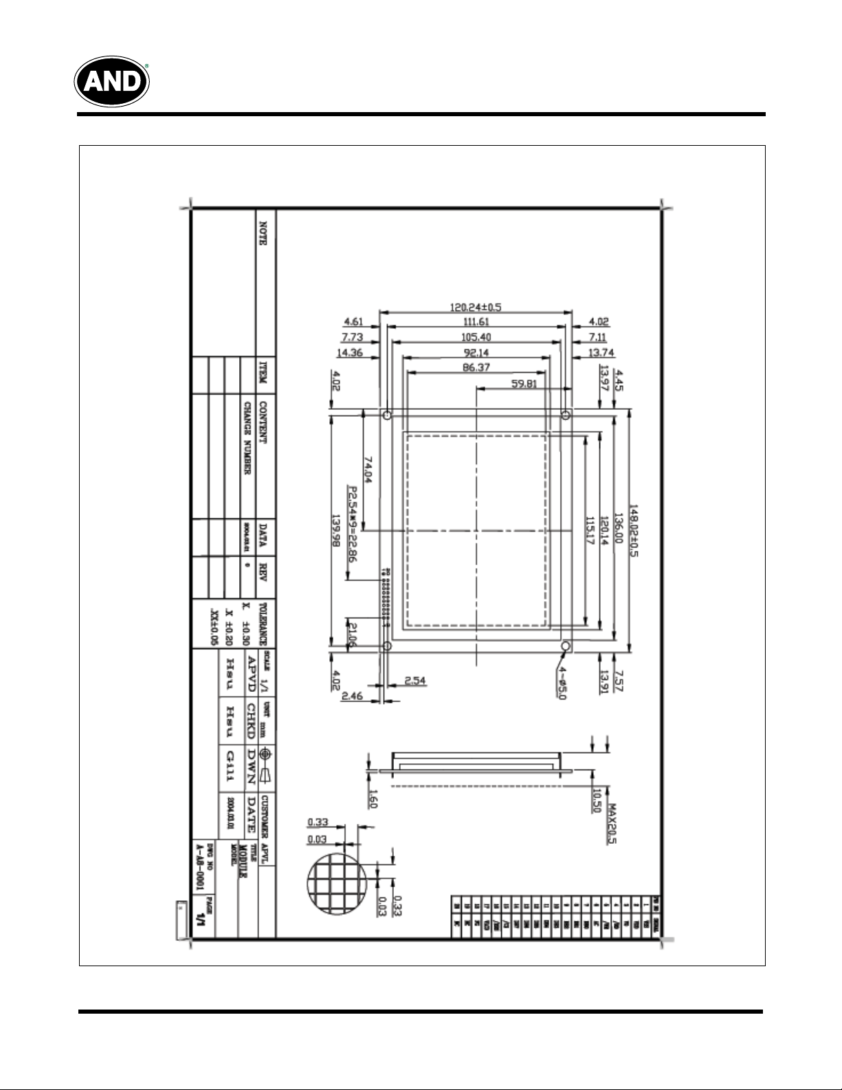
Displays
Dimensional Outline
AND3222MST-LEDW
Unit: mm
Standard Tolerance: 0.5mm
2
Purdy Electronics Corporation • 720 Palomar Avenue • Sunnyvale, CA 94085
Tel: 408.523.8200 • Fax: 408.733.1287 • email@purdyelectronics.com
www.purdyelectronics.com
5/1/08
φ
φ
φ
φ
λ
Displays
AND3222MST-LEDW
Optical Characteristics
Item Symbol Condition Min. Typ. Max. Unit
f (12 o’clock)
Viewing angle range
Rise time Tr
Fall time Tf 170 ms
Frame frequency Frm – 64 – Hz
Contrast Cr – 4.5 –
Brightness of Backlight L
Peak Emission
Wavelength
b (6 o’clock)
l (9 o’clock)
r (3 o’clock)
P 567 570 576 nm
When Cr ≥ 1.4
V
-V
=24.3V
DD
O
Ta=25ºC
IF = 180 mA
Environmental Absolute Maximum Ratings
Normal Temperature Wide Temperature
Item
Ambient Temperature 0 ºC +50 ºC -20 ºC +70 ºC -20 ºC +70 ºC -30 ºC +80 ºC
Humidity (without
condensation)
Note 2: Ta ≤ 50ºC: 80% RH max; Ta > 50ºC: Absolute humidity must be lower than the humidity of 85% RH at 50ºC
Note 3: Ta at -20ºC will be < 48 hrs at 70ºC will be <120 hrs when humidity is higher than 75%.
Note 4: Background color changes slightly depending on ambient temperature. This phenomenon is reversible.
Note 5: Ta ≤ 70ºC: 75% RH max; Ta > 70ºC: absolutely humidity must be lower than the humidity of 75% RH at 70ºC.
Note 6: Ta at -30ºC will be < 48 hrs, at 80ºC will be < 120 hrs when humidity is higher than 75%.
Operating Storage Operating Storage
Min. Max. Min. Max. Min. Max. Min. Max.
See Note 2, 4 See note 3, 5 See Note 4, 5 See Note 4.6
–20–
–40–
–30–
–30–
175 ms
10 20 –
degree
cd/m
2
Interface Pin Assignment
Pin No.
10 DB3 H/L Data Bus Line 20 K GND LED Ground External (White)
5/1/08
Pin Out Level Description Pin No. Pin Out Level Description
1 VSS 0V Power Supply Ground 11 DB4 H/L Data Bus Line
2 VDD 5V Logic Supply Voltage 12 DB5 H/L Data Bus Line
3 VO – Contrast Adjustment Voltage 13 DB6 H/L Data Bus Line
4 /RD L Read Signal 14 DB7 H/L Data Bus Line
5 /WR L Write Signal 15 /CS L Chip Signal
6 AO H/L Data Type Select 16 /RST L Reset Signal
7 DB0 H/L Data Bus Line 17
8 DB1 H/L Data Bus Line 18 FG – For GND
9 DB2 H/L Data Bus Line 19 A 4.2V LED Power External (Red)
Purdy Electronics Corporation • 720 Palomar Avenue • Sunnyvale, CA 94085
Tel: 408.523.8200 • Fax: 408.733.1287 • email@purdyelectronics.com
V
LCD
– Power Supply Voltage for LCD
www.purdyelectronics.com
3
Displays
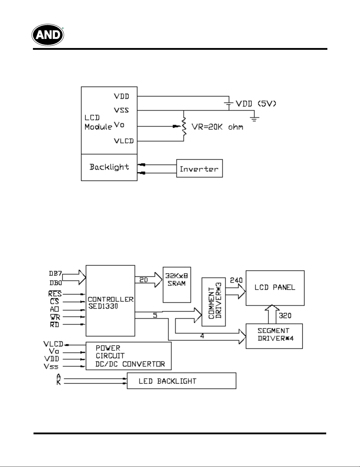
Power Supply
AND3222MST-LEDW
Block Diagram
4
Purdy Electronics Corporation • 720 Palomar Avenue • Sunnyvale, CA 94085
Tel: 408.523.8200 • Fax: 408.733.1287 • email@purdyelectronics.com
www.purdyelectronics.com
5/1/08
Displays
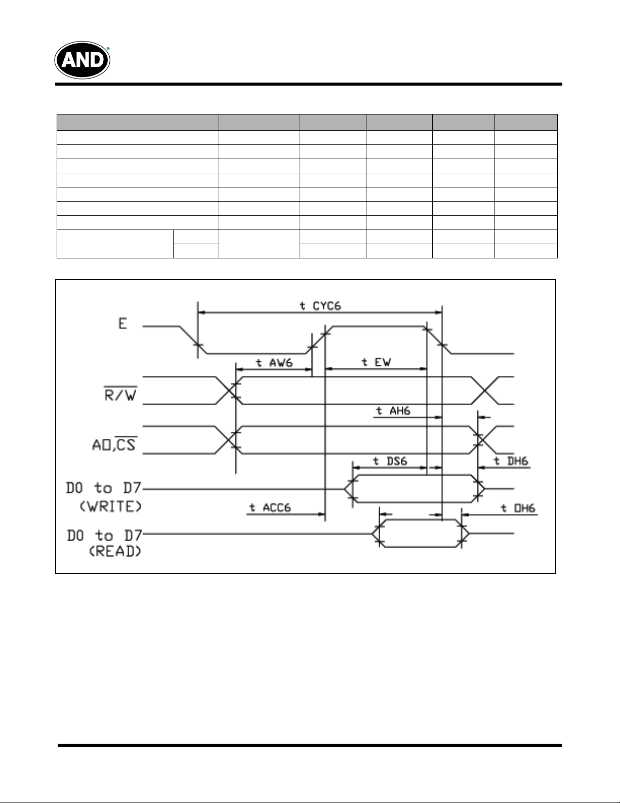
Timing Characteristics
Item
System Cycle Time tCYC 425 – – ns
Address Set-up Time tAW 30 – – ns
Address Hold Time tAH 10 – – ns
Data Set-up Time tDS 120 – – ns
Data Hold Time tDH 10 – – ns
Output Disable Time tOH 10 – 50 ns
Access Time tACC – – 120 ns
Enable Pulse Width
AND3222MST-LEDW
Symbol Min. Typ. Max. Unit
Read
Write 220 – – ns
tEW
220 – – ns
5/1/08
Purdy Electronics Corporation • 720 Palomar Avenue • Sunnyvale, CA 94085
Tel: 408.523.8200 • Fax: 408.733.1287 • email@purdyelectronics.com
www.purdyelectronics.com
5
 Loading...