

∆ λ
∆ λ
OPTOELECTRONICSOPTOELECTRONICSOPTOELECTRONICS
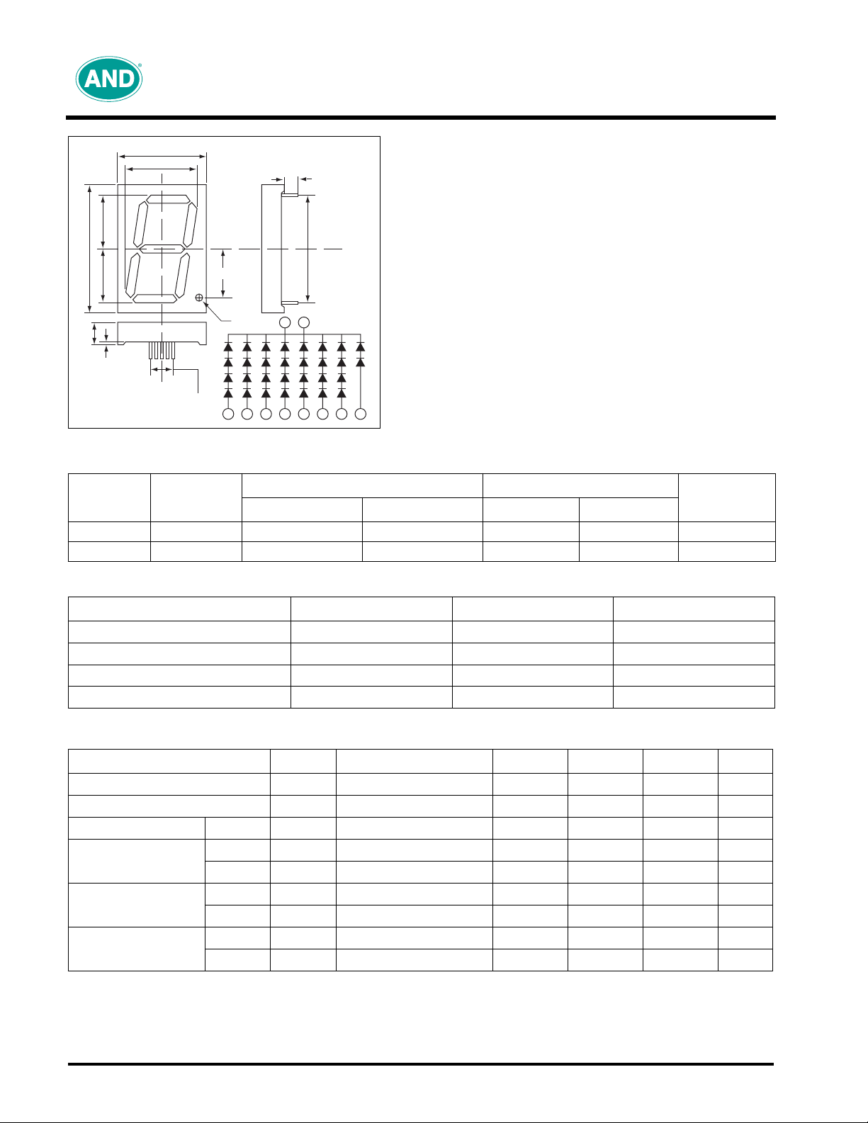
Unit: mm
12.0
70.0
28.5
28.5
1.0
0.5
All Pin
47.76
41.5
A
G
E
No. 1
2.54 X 4 = 10.16
C
D
5
BF
25.75
DP
E D C B A
5.5ø
3.5 min.
60.0
No. 5
1 5
F G DP
Description
Size
2.3 inch 1 AND-2307SCL AND-2307SAL Red Red 10
2.3 inch 1 AND-2307GCL AND-2307GAL Green Gray 10
Number
of Digits
Cathode Anode Display Face
Common Color
Product specifications contained herein may be changed without prior
notice. It is therefore advisable to contact Purdy Electronics before
proceeding with the design of equipment incorporating this product.
AND-2307 Series
GaAsP/GaP–Red; GaP–Green
7 Segment, Large Size; 2.3 Inch
Features
• Large size—7 segment displays
• Available in red or green
• Suitable for large size displays for distance viewing;
across-the-building status displays
• Available in both common cathode and common anode
RoHS Compliant
•
LED Displays
Number
of Pins
Absolute Maximum Ratings (T = 25°C)
Characteristics Symbol Rating Unit
DC Forward Current/Segment
Reverse Voltage/Segment
Operating Temperature Range
Storage Temperature Range
(DC)/SEG
F
V
R
T
Opr
T
Stg
30 mA
3 (Red), 5 (Green) V
-25 to 85 °C
-25 to 100 °C
I
Electro-Optical Characteristics (T = 25°C)
Characteristics Symbol Test Condition Minimum Typical Maximum Unit
Forward Voltage/Segment
Forward Voltage/D.P.
Reverse Current
Luminous Intensity
Per Segment
Peak Emission
Wavelength
Spectral Line
Half Width
Precaution
Please be careful of the following:
1. Soldering temperature: 260°C max; Soldering time: 3 sec. max; Soldering portion of lead: up to 2 mm from the body of the device.
2. The lead can be formed up to 5 mm from the body of the device without forming stress. Soldering should be performed after the lead
forming.
Red
Green
Red
Green
Red
Green
V
F
V
F
I
R
I
V
I
V
λ
P
λ
P
I
= 20 mA
F
I
= 10 mA
F
V
= 3 (Red), 5 (Green)
R
I
= 10 mA
F
I
= 10 mA
F
I
= 10 mA
F
I
= 10 mA
F
I
= 10 mA
F
I
= 10 mA
F
– 8.4 12.0 V
–4.26.0V
– – 100 µA
4.7 7.8 – mcd
4.1 6.8 – mcd
– 635 – nm
– 567 – nm
–40–nm
–30–nm
Tel: 408.523.8200 • Fax: 408.733.1287 • email@purdyelectronics.com • www.purdyelectronics.com
Purdy Electronics Corporation • 720 Palomar Avenue • Sunnyvale, CA 94085
7/18/07
AND-2307 Series
GaAsP/GaP–Red; GaP–Green LED Displays
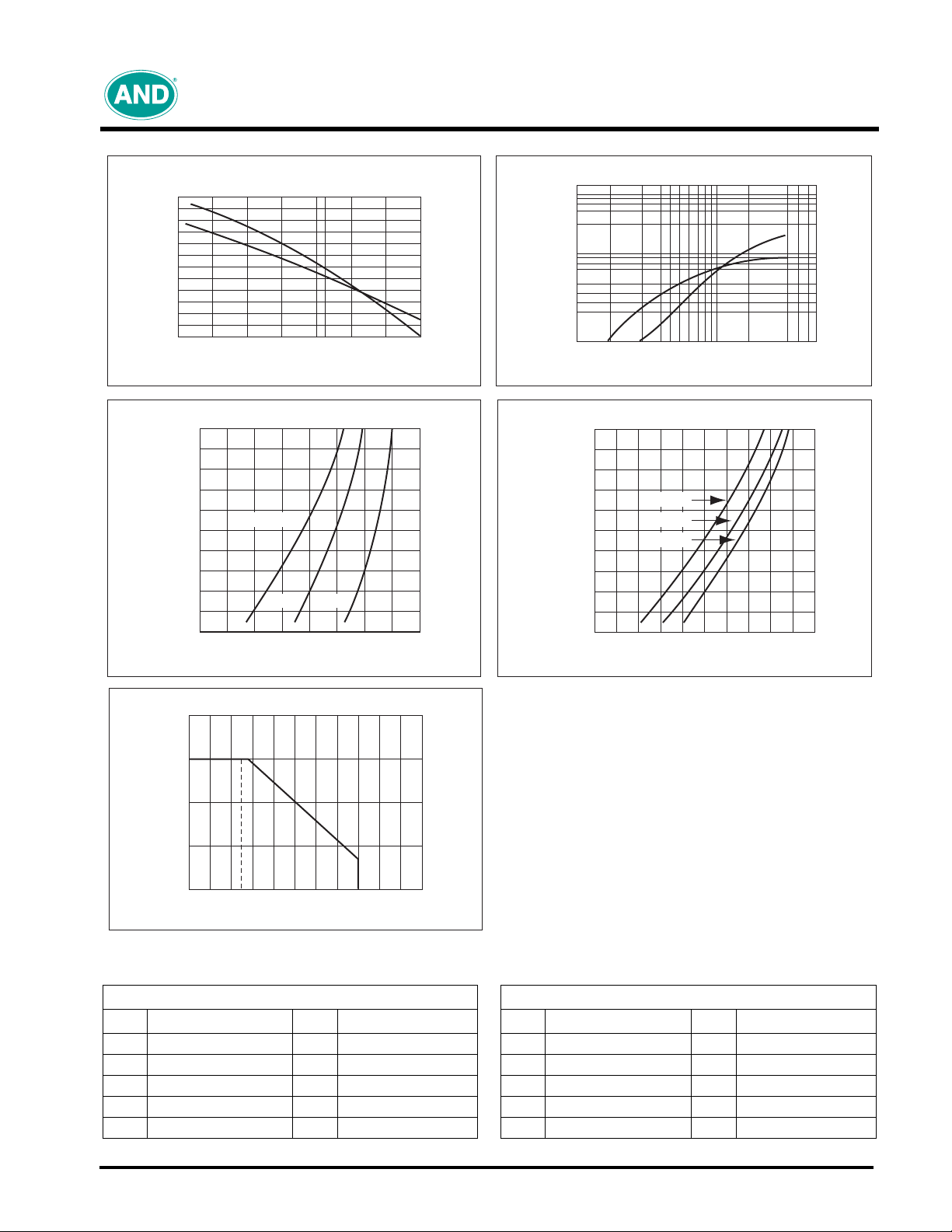
Luminous Intensity vs. Temperature
1.5
1.0
Relative Intensity
0.5
Red
Green
-20 20
-40 40 60 800
Temperature
Forward Current vs. Forward Voltage (Red GaAsP)
50
40
30
20
10
+100°C
+25°C -5°C
Luminous Intensity vs. Forward Current
10
Luminous Intensity (mcd)
1
Forward Current vs. Forward Voltage (GaP)
50
40
30
20
= Forward Current (mA)
10
F
I
210
1 20 30 (mA)3
Forward Current
+100°C
+25°C
-5°C
Green
Red
= Forward Excitation Current (mA)
0
F
I
6.0
Max Current vs. Temperature
30
20
10
Max. Current (mA)
0
20
7.0 8.0 9.0 10.0
VF = Forward (V)
40 60 80 100
Ambient Temperature
0
6.0 8.0
VF = Forward Voltage (V)
10.0
AND-5610 Series Pin Connection Table
AND-2307SCL AND-2307SAL
Pin Connection Pin Connection Pin Connection Pin Connection
1
Common Cathode
2
Anode E
3
Anode D
4
Anode C
5
Common Cathode
6
7
8
9
10
Anode B
Anode A
Anode dp
Anode F
Anode G
1
Common Anode
2
Cathode E
3
Cathode D
4
Cathode C
5
Common Anode
6
7
8
9
10
Cathode B
Cathode A
Cathode dp
Cathode F
Cathode G
Tel: 408.523.8200 • Fax: 408.733.1287 • email@purdyelectronics.com • www.purdyelectronics.com
Purdy Electronics Corporation • 720 Palomar Avenue • Sunnyvale, CA 94085
7/18/07
 Loading...